Did you consider machining your own pulleys? vs buying them. I would think them to be far easier to machine then say a gear. Depending on the belt, some have rounded drive "cogs" that would seem might match a ball nose end mill. For square drive perhaps a slightly modified end mill might work (if it needs a slight taper on the drive cogs). I'm probably not making much sense. Myfordboy on YouTube had an example of making a similar pulley (or set of pulleys). Might be able to find cheap timing type belt on Amazon or an industrial supplier like say McMaster Caar. I've heard that McMaster does ship to Canada and I've heard otherwise but on their site, help section they seemed to indicated shipping to US and most of Canada so it might be worth double checking.

You are using an out of date browser. It may not display this or other websites correctly.
You should upgrade or use an alternative browser.
You should upgrade or use an alternative browser.
Rupnow Ovehead Cam Air Cooled
- Thread starter Brian Rupnow
- Start date


Help Support Home Model Engine Machinist Forum:
This site may earn a commission from merchant affiliate
links, including eBay, Amazon, and others.
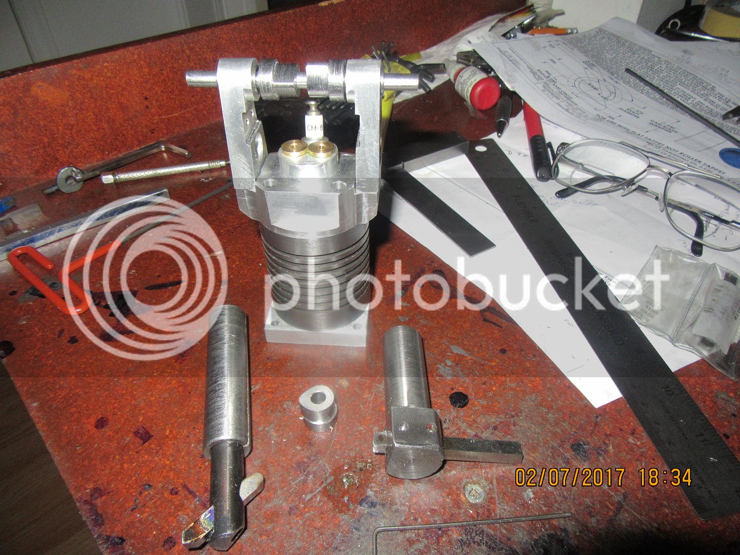
You can call me Two-cam-Sam!! There are a few things going on in this picture. The cam I machined yesterday just wasn't going to do it. I used the cobbled together boring tool on the left in my boring head to make yesterdays cam, and due to the long skinny shank it deflected enough that the cam surfaces were all slightly tapered. ------So, I made a new heavier, shorter boring tool with a newly ground HSS cutter in it, and made two new cams today. No deflection, and the new cams came out very accurately with no visible taper on the outer diameter. And yes people, the boring head would have unscrewed from the shank if I had been running the mill in reverse. The cams I had made prior to this, using the "boring head method" were mainly from brass, and presented no real challenge to the boring tool. These guys however, are made from 01 drill rod, and it was definitely a "thumping old time" cutting them. I'm glad that someone pointed out the error of my ways, and that I didn't suffer a catastrophe with the boring head coming unscrewed.


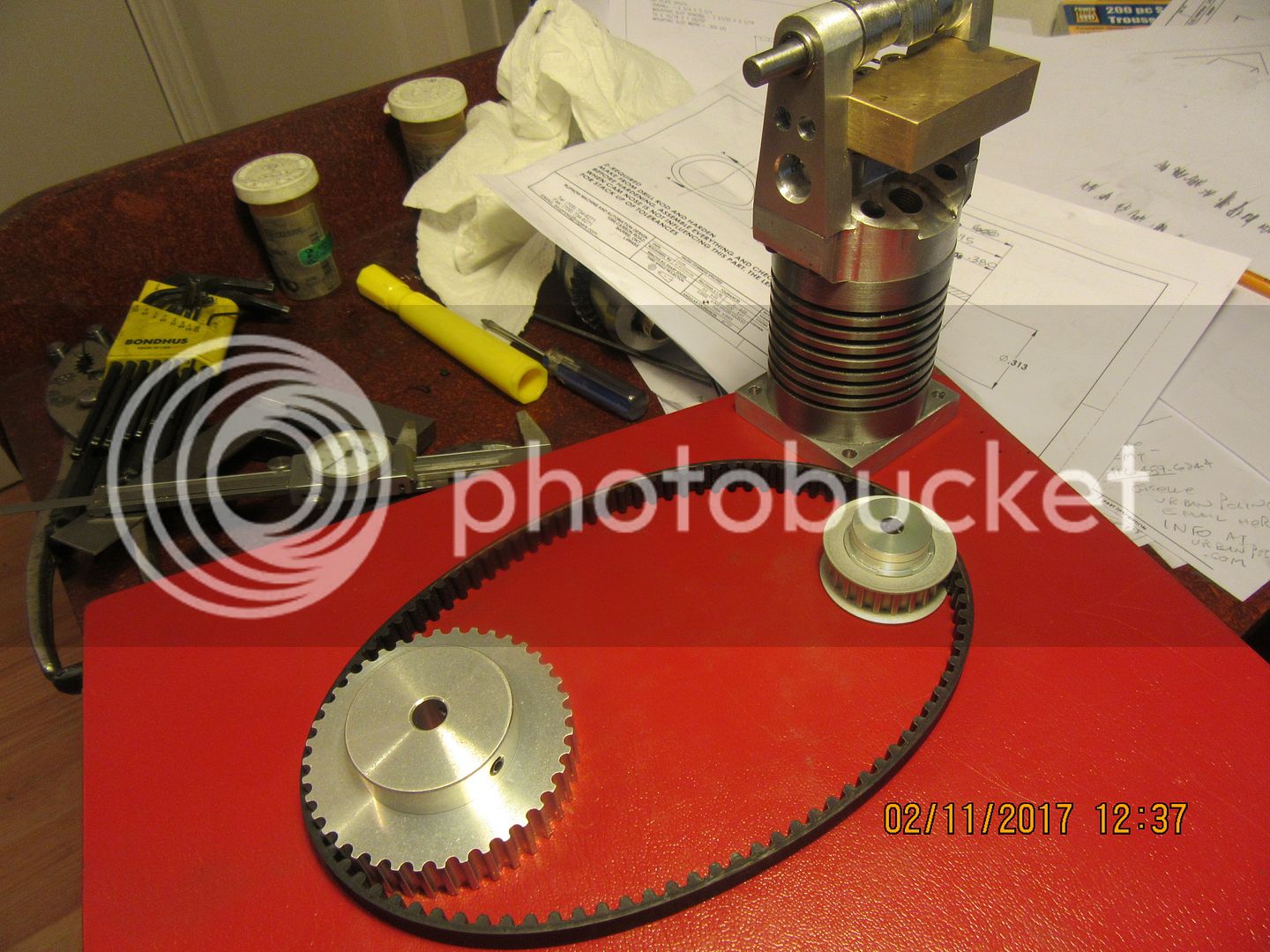
Mark--I did consider it, albeit briefly. The cuts would require a specially ground milling cutter, or massive screwing around tilting either the head of the mill or the base of the rotary table to give the included angle called for in the slots on this type of pulley. I was just p.off about the people who sell these pulleys in the USA but wouldn't mail them to Canada. I found another company in the USA who will mail them to Canada, so I ordered from them. McMaster Carr will ship to Canada IF you had a pre-existing account with them before their rules changed about 5 years ago, but they will not open any new accounts in Canada.---BrianDid you consider machining your own pulleys? vs buying them. I would think them to be far easier to machine then say a gear. Depending on the belt, some have rounded drive "cogs" that would seem might match a ball nose end mill. For square drive perhaps a slightly modified end mill might work (if it needs a slight taper on the drive cogs). I'm probably not making much sense. Myfordboy on YouTube had an example of making a similar pulley (or set of pulleys). Might be able to find cheap timing type belt on Amazon or an industrial supplier like say McMaster Caar. I've heard that McMaster does ship to Canada and I've heard otherwise but on their site, help section they seemed to indicated shipping to US and most of Canada so it might be worth double checking.
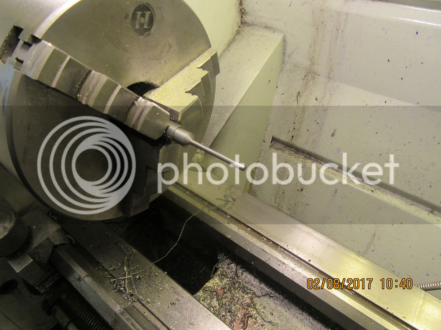
This is a rare picture of a valve being born!! I turn the small diameter down in three 1/2" long stages, aiming for about .002" larger in diameter than the targeted 0.125". This avoids the issues with deflection that would come up if you tried to turn the entire 1.5" length all at once. Then, using the cylinder head with the valve cages reamed to size as a "try it and see if it fits" guide, I remove the remaining material with 220 grit garnet cloth strips as the lathe is running. When the valve shank just fits into the valve cage reamed hole for it's full length, that part is finished. I set the topslide over to give me a 92 degree included angle on the valve, and then very carefully cut the valve face. I will now cut off the valve from the parent stock with about 2" of the parent stock remaining, which gives me a "handle" to hold and spin by hand while I lap the valve into the seat in the valve cage. The valve stem is unusually long because of the type of engine it is going to be used in, but 2/3 of that length will be guided, so I'm not real concerned about it bending. the valve is made from common 1018 steel.

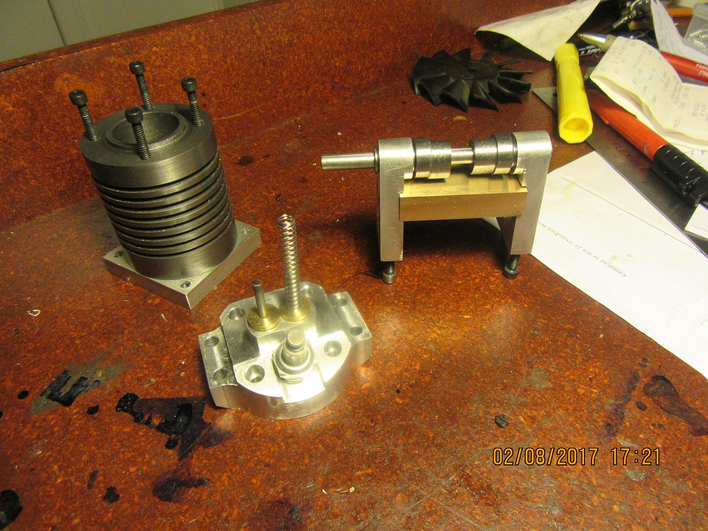
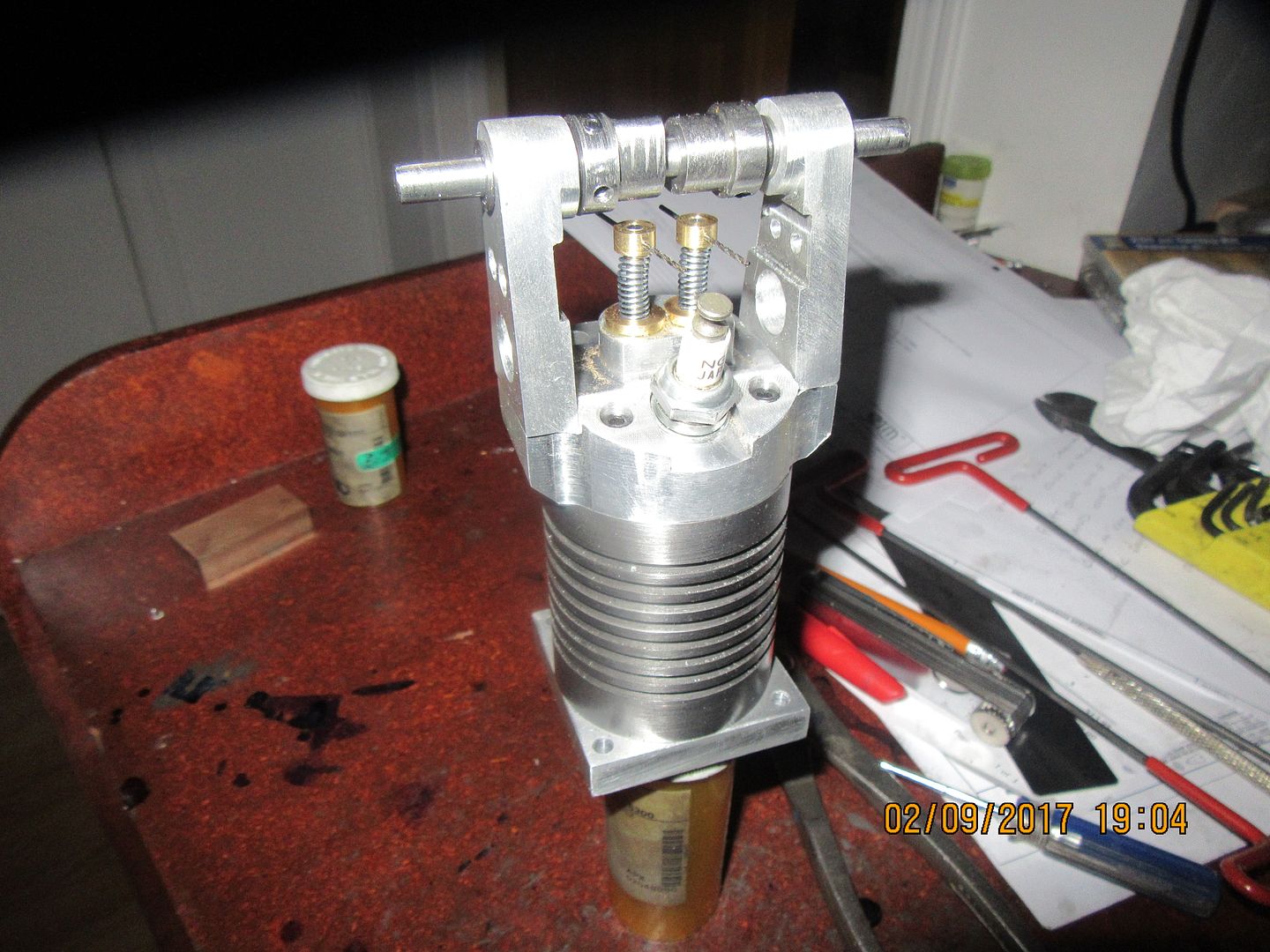
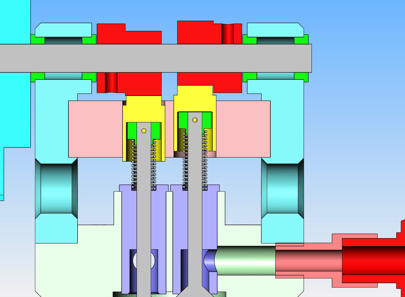
Both valves are machined, lapped into their seats, and cut to length. I machined a piece of bronze for the bridge that the "lifters" slide in, although I haven't cut it to length nor tapered the sides yet to match the cam towers. I bought a big box of assorted springs at a hardware store two weeks ago, and have found what I think should be a good spring (it's setting on one of the valve stems in the picture). The spring is 0.215" outside diameter x 0.020" diameter wire. I think I will buy a 7/32" (0.219") endmill and put a .050" deep pocket in the top of each valve cage to keep the spring centered. I will probably modify the "spring keeper" that is pinned to the end of each valve stem to keep them centered at the top end as well. When I rotate the cams thru 360 degrees, they clear the top of the bronze, which is great.--That's the way I planned it, but it it's always nice to have your design confirmed in metal. Tomorrow I have to go down to western Ontario to present a new proprietary automation design to a customer, so I may not get back to the engine until Saturday.

It's been a busy day!! I got up early this morning and mushed my Huskies down to Ingersoll, Ontario for a design review of a project I have been working on. Had a 1 hour meeting with a bunch of "suits" and then turned around and drove home. I'm getting too old for this s$%t but find it hard to turn down the money. When I got home I made the "keepers" that hold the springs on the valves, cross drilled the keepers and the valve stems with a 1 mm drill (You can see the 1 mm drills in there as temporary "pins). I machined pockets into the tops of the valve cages to act as "locators" for the springs, and assembled the valves, springs and keepers. I also drilled and tapped the cams for two #6-32 set screws each. I had to get this far so I can measure between the ends of the valve stems and the flat part of the cams so I will know how long to make the yellow pieces I refer to as "lifters". I have a "theoretical" length in my model, but due to stack up of tolerances the actual measurement is going to be a bit different than the 'theoretical". Not a big difference really, only about .013", but when the valve lash is only 0.006" to 0.008", you have to get it right.


Herbie, there has to be more to the picture than I can see. I don't know for sure, but I think American companies wanting to sell into Canada get hassled right to death by our taxes, tariffs, and political bull$h&t. One would not think that to be so, but there has always been issues buying stuff into Canada from USA. And every year it seems to get a bit worse.
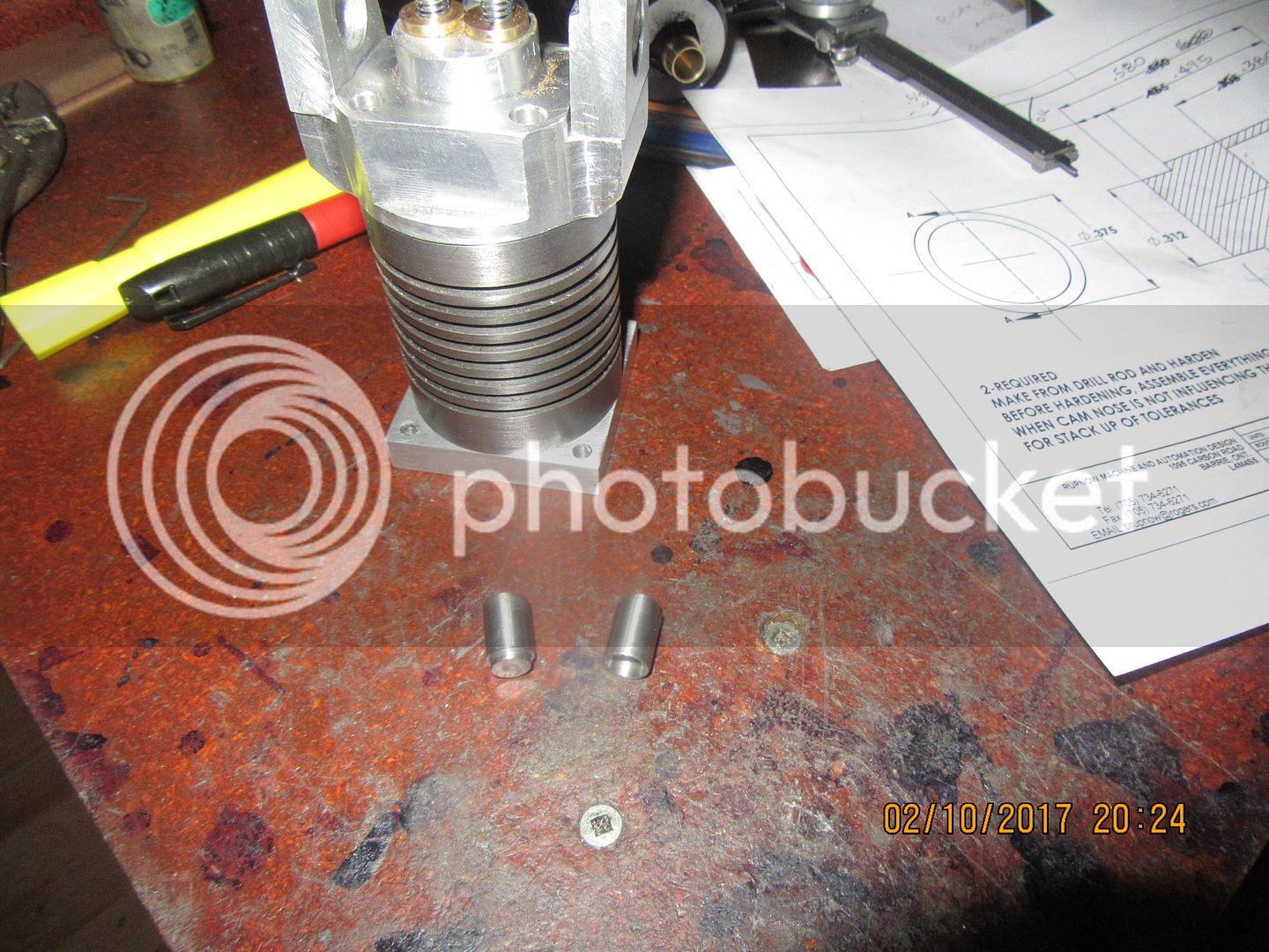
Today after work, I made a pair of "lifters" out of 01 drill rod. They aren't real pretty, but they are dimensionally accurate. Since I don't have the bronze "bridge" that they fit into yet, I reamed a 3/8" hole in a piece of brass scrap, and turned the outer diameter to a snug "sliding fit".--Well, that's a lie.--I made them from 3/8" drill rod, which is so close to being a full 3/8" in diameter that it won't fit into a reamed 3/8" hole. I used #240 grit garnet cloth strips and "sanded" the piece of 3/8" drill rod in the lathe until it was a snug sliding fit into the reamed hole. Snug is good. If they are a bit tight in the bridge after I heat treat them, a bit of 600 grit compound will fix that in short order. The flat end is in contact with the cam. The hollow end fits down over top of the valve stem and spring keeper. Much careful measuring was done before I arrived at numbers that fit my particular situation. I haven't drilled the inlet nor the exhaust passages in the head and valve cages yet, so the valves will be removed, the drilling and tapping of passages completed, and then a complete assembly including the yet to be made bronze bridge will be set up to check clearances before hardening the cams and lifters.

Look what showed up at my house today. I'm impressed, they look great, but it makes me crazy that something that started out in USA for $46 ends up costing me $106 Canadian funds by the time it gets to my house.

This is a short video showing the operation of the overhead valve train in operation. Please let me know if you can see it okay.--Brian
[ame]https://www.youtube.com/watch?v=KgNTsMqnWvc&feature=youtu.be[/ame]
[ame]https://www.youtube.com/watch?v=KgNTsMqnWvc&feature=youtu.be[/ame]
Brian,
Could see it no problems. The "lifters" are called followers or cam buckets in this setup.
Cheers
Andrew
Could see it no problems. The "lifters" are called followers or cam buckets in this setup.
Cheers
Andrew
DavidLloyd2
Well-Known Member
- Joined
- Jul 16, 2016
- Messages
- 84
- Reaction score
- 111
Brian,
I can see it okay.
Cheers
DavidLloyd
I can see it okay.
Cheers
DavidLloyd
- Joined
- Aug 7, 2014
- Messages
- 57
- Reaction score
- 68
Good work Brian, the work you have produced is spot on to get the clearance right between the cam and the lifters.
I have built a similar overhead version and purposely left a bit of extra material on the lifters so that once the cam assembly is attached, small adjustments can be made to the face of the lifters to get the clearance required to ensure seating of the valves. This saves having to work to exact measurements during the major cam part machining, which might help some from having slightly off dimensions during manufacture. On full sized versions, they use small shims beneath the lifters and top of the valve stems to get the clearances right but that requires much more fiddly work making the shims on an engine this size.
Looking forward to seeing this one run.
Steve
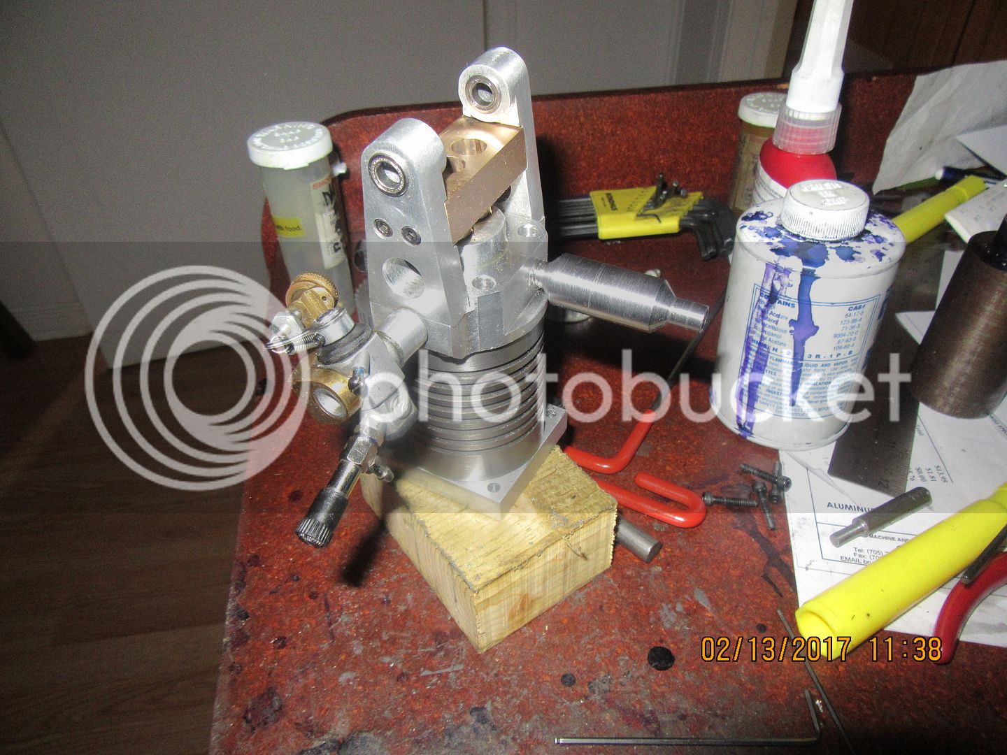
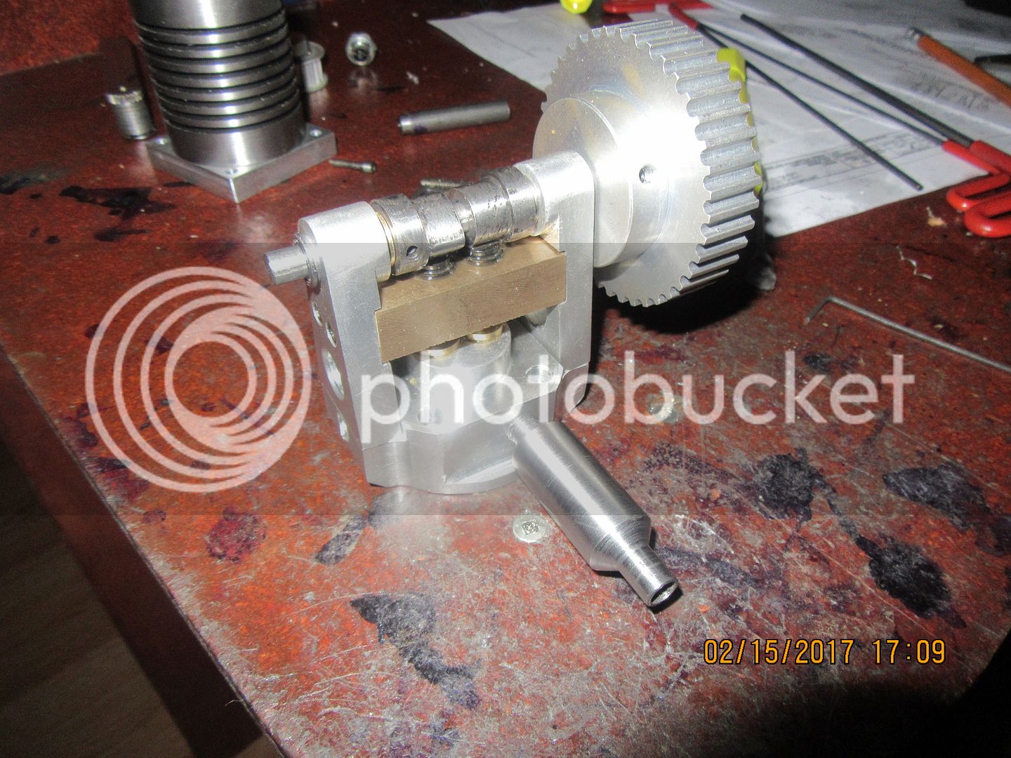
I discovered this morning that I didn't have any 5/8" diameter brass to build an exhaust from. Lots of 1018 round steel 'shorts" though, so that's what I have for a muffler. I need to sand the o.d. a bit more to get any tooling marks out, but it's another part done. The carb I will be using with the correct adapter is also "posed" in the picture. The ports are drilled and tapped into the head and thru the valve cages, and the cams and cam followers will be heat treated later today.

Well, the cams are in the oven---Kinda sounds like the beginning of a song, doesn't it!! I heated the cams and the cam followers to a orange/ red (Had a piece of coat hanger wire thru the cams so I could manage them without flame hardening my fingers.) The followers have no thru hole, so they were supported by a "hook" in the end of another piece of coat hanger wire. I don't like to get things like this too hot. If you burn them (which is very easy to do with oxy acetylene) they are ruined. At what I thought was the right temperature they were lowered into a soda can of #30 motor oil and swished around. after they cooled, I pre-heated good wifes kitchen oven to 400 degrees and set them in an old cake pan, where they are quietly spending the next hour heat-soaking. At the last minute, after they were in the oven, I had a moment of self doubt--"Was that piece I cut thing out of really 01??--So, I grabbed the piece of material I had cut them from, ran out to the shop, heated the end of the rod and swished it around in the same oil till it cooled off. Then, back into the machine shop for the "file test". Yep, harder than the devil's horn!!! Now I have to go turn on the vent fan over the stove, before I stink up the house too much and lose my kitchen privileges.
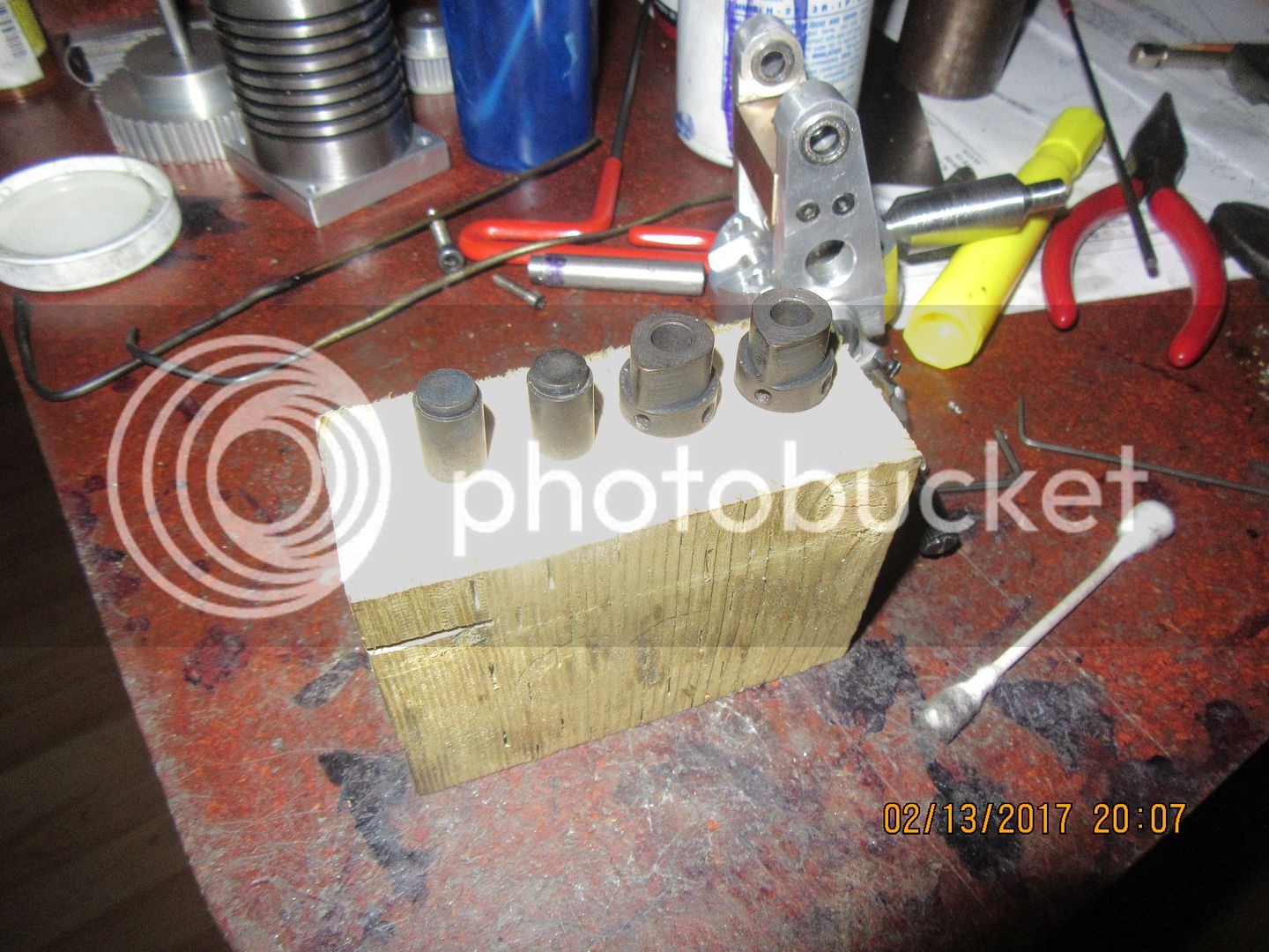
I can't really tell what the 1 hour heat soaking at 400 degrees has done to the material, but the quenching in oil has certainly turned them black. Funny, they don't look as black in the picture as they do in reality. The piece of material that I hardened the end of to check and make sure it was really 01 material is undergoing it's own 1 hour heat soak right now. When it is finished, and cools off, I will re-try it with my file to see if I detect any difference.

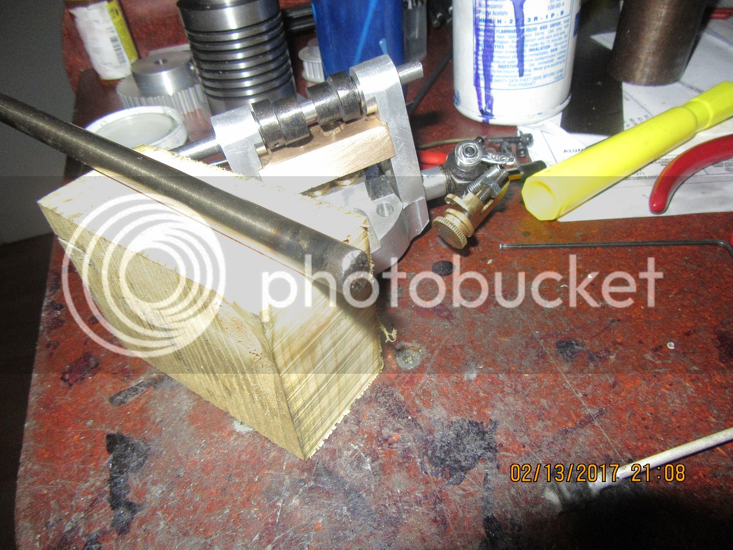
I'm happy to report that my home-grown heat treat and tempering has come out very well. This is my "test and control" piece, which was heated to orange/red with oxy acetylene, quenched in oil, then heat-soaked in my kitchen oven for 1 hour at 400 degrees. Before the heat soak (tempering), a file just skated off with no cutting visible at all. After the heat soak, a file will cut it, as you can see, but it is still really hard. Without more scientific means to test what I have accomplished, I believe I can say this was a successful outcome.

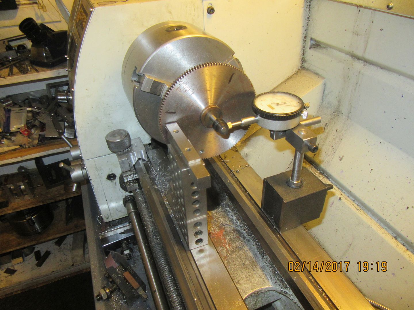
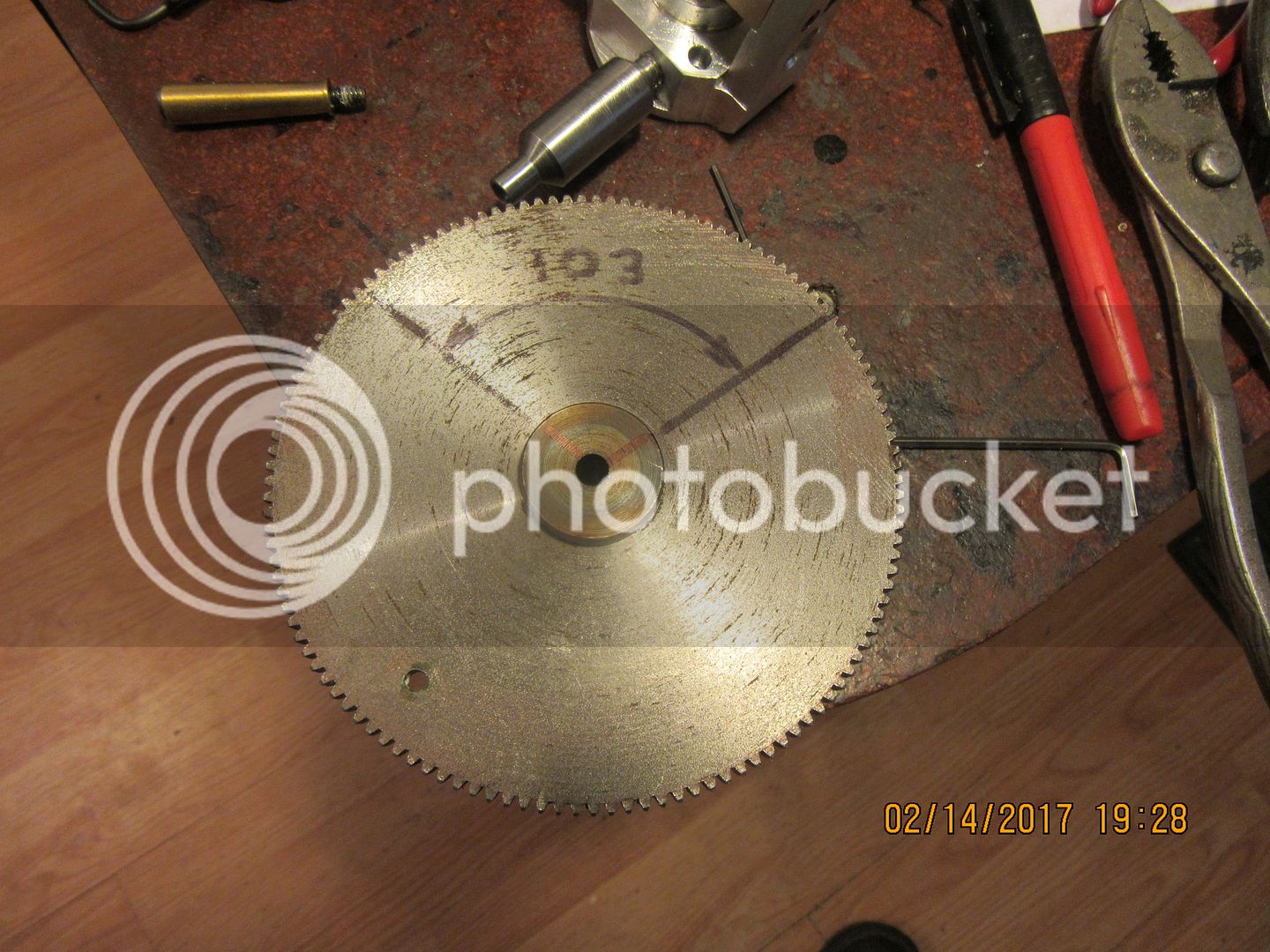
After making my cams using the "quick and nasty" method in the vertical mill, I was curious about how closely the milled profile matched the actual design drawing, which asked for 125 degrees of cam influence. (that is the number of degrees that the cam actually is lifting the cam follower.) Since there is a 1:2 ratio between the camshaft and crankshaft, that translates to 250 degrees of influence on the valve during one full rotation of the crankshaft. Which is fine.--The exhaust valve begins to open 50 degrees before bottom dead center, remains open thru a full 180 degrees of movement from bottom dead center to top dead center, then closes completely about 20 degrees into the intake stroke. I thought up all kinds of wild schemes on how to measure the angularity of my cams (they actually turned out "spot on" dimensionally.) I ended up doing what you see in the picture, which is extra neat because I didn't have to make anything. I have an old change gear with a hub in it which has a 1/4" bore, that is used for the automatic carriage feed on my model sawmill. I put it and one of the cams on a piece of 1/4" shaft and put it in the chuck of my lathe. I then took my dedicated dial indicator with a flat "foot' on it which I use for setting up my four jaw chuck and set the "foot" against the cam. I stacked up some 1 2 3 blocks and some parallels to be the same height as the center of the chuck. Then turning the chuck by hand, I could see very clearly when the lobe on the cam started to affect the dial indicator, and put a mark on the gear face at the top of my stack of blocks. Then I turned the chuck by hand in the opposite direction until I seen the dial indicator needle start to move again, and scribed another line. The angular separation between the two marks was then measured with a drafting protractor. This yielded 103 degrees instead of 125 degrees, but that's okay. At 206 degrees of influence on the valves, I will begin to open the exhaust valve 20 degrees before bottom dead center, stay open thru 180 degrees, and close 6 degrees after top dead center. My aim was not to have a high revving engine, so for a low revving engine this should work just fine.


The cylinder head assembly is all back together, and everything fits. Non of the parts I hardened or heat treated changed shape in any significant way. I have just had one of those "King Midas in reverse" afternoons, where everything I touched turned to poop!!! There is a thin brass spacer between the cams and the flanged bearing on each side to keep things positioned properly. I hunted around in my precious metals (brass and bronze) bin and found a very short piece of 3/4" brass that should have worked. First I made them too big around, matching the cam tower diameter, and not the flange bearing. Then I drilled the hole in the center undersize--(drill was in the wrong spot in the drill index.) Then I mounted them on a stub arbor to reduce the diameter and they ended up radically unconcentric with the center hole. Then I said something nasty, threw them in the waste box, and started over again with a new piece of brass. At that point I decided I better quit for the day, so I detailed the piston and con rod. I don't often have afternoons like this, but when I do it really makes me appreciate the days when things go right!!!

Similar threads
- Replies
- 6
- Views
- 3K
- Replies
- 57
- Views
- 11K
- Replies
- 30
- Views
- 7K