Read post #14.Brian,
Why not just bore that on the mill?
You are using an out of date browser. It may not display this or other websites correctly.
You should upgrade or use an alternative browser.
You should upgrade or use an alternative browser.
Rupnow i.c. Engine with governor
- Thread starter Brian Rupnow
- Start date

Help Support Home Model Engine Machinist Forum:
This site may earn a commission from merchant affiliate
links, including eBay, Amazon, and others.
jwcnc1911
-jwcnc191
- Joined
- Mar 19, 2013
- Messages
- 603
- Reaction score
- 86
My bad, got to quit reading this on my phone. Miss too much.
So why do you have to change the feature to make this cut on your mill?
Just curious, I'm not seeing why the feature must be changed. I would have preferred this cut on the mill anyway.
So why do you have to change the feature to make this cut on your mill?
Just curious, I'm not seeing why the feature must be changed. I would have preferred this cut on the mill anyway.
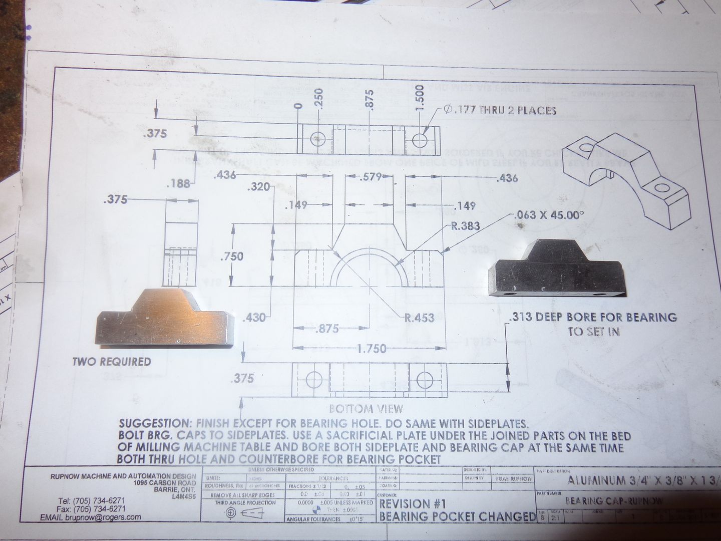
Read post 14.--Look at the picture!!!--To expand on that a bit---Unless you have a very expensive boring head, that lets you set the cutter out farther from center WHILE THE MILL IS RUNNING you can't make the kind of cut I had detailed previously. I have got caught on this one before myself. You have to shut the mill off to adjust the boring head. If the boring head cutter is between two "ridges" of material on each side of the plate, you can't adjust it out farther in the hole, because there is material in the way. You can't withdraw it out of the plate to set the tool out farther or when you go back into the plate you cut one of the ridges away that you wanted to keep. That one is a bit of a head scratcher. You can do it in the lathe however, because you can adjust the boring tool to cut the hole larger by retracting the cross feed while the chuck is spinning. That's why my original plan was to do it in the lathe.My bad, got to quit reading this on my phone. Miss too much.
So why do you have to change the feature to make this cut on your mill?
Just curious, I'm not seeing why the feature must be changed. I would have preferred this cut on the mill anyway.
Last edited:
jwcnc1911
-jwcnc191
- Joined
- Mar 19, 2013
- Messages
- 603
- Reaction score
- 86
Rivergypsy
Well-Known Member
- Joined
- Oct 15, 2010
- Messages
- 432
- Reaction score
- 222
Many thanks for the drawings, Brian - Roll on getting my hands on some material on Monday 
A quick question, please - are you allowing 'artistic license', or would you prefer all engines to be a perfect scale copy? Just checking, as I occasionally get the urge to tweak parts as I'm machining them. I'm not saying in the slightest that I don't love your engine, but i just know what I'm like...
A quick question, please - are you allowing 'artistic license', or would you prefer all engines to be a perfect scale copy? Just checking, as I occasionally get the urge to tweak parts as I'm machining them. I'm not saying in the slightest that I don't love your engine, but i just know what I'm like...
RiverGypsy--after 48 years as a design engineer for industry, I tend to put more emphasis on functionality rather than on cosmetic appeal, I know that. If you pretty it up some, I won't be offended at all. Just try hopefully to keep most of the major dimensions the same please.---BrianMany thanks for the drawings, Brian - Roll on getting my hands on some material on Monday
A quick question, please - are you allowing 'artistic license', or would you prefer all engines to be a perfect scale copy? Just checking, as I occasionally get the urge to tweak parts as I'm machining them. I'm not saying in the slightest that I don't love your engine, but i just know what I'm like...
Rivergypsy
Well-Known Member
- Joined
- Oct 15, 2010
- Messages
- 432
- Reaction score
- 222
Many thanks for your reply Brian - I didn't want to offend you.
Lol, I'm just an old tart when it comes to engines
I was thinking of pocketing some of the faces of the side pieces and head to give the appearance of cast in ribs, with radiused corners. What do you think?
Lol, I'm just an old tart when it comes to engines
I was thinking of pocketing some of the faces of the side pieces and head to give the appearance of cast in ribs, with radiused corners. What do you think?
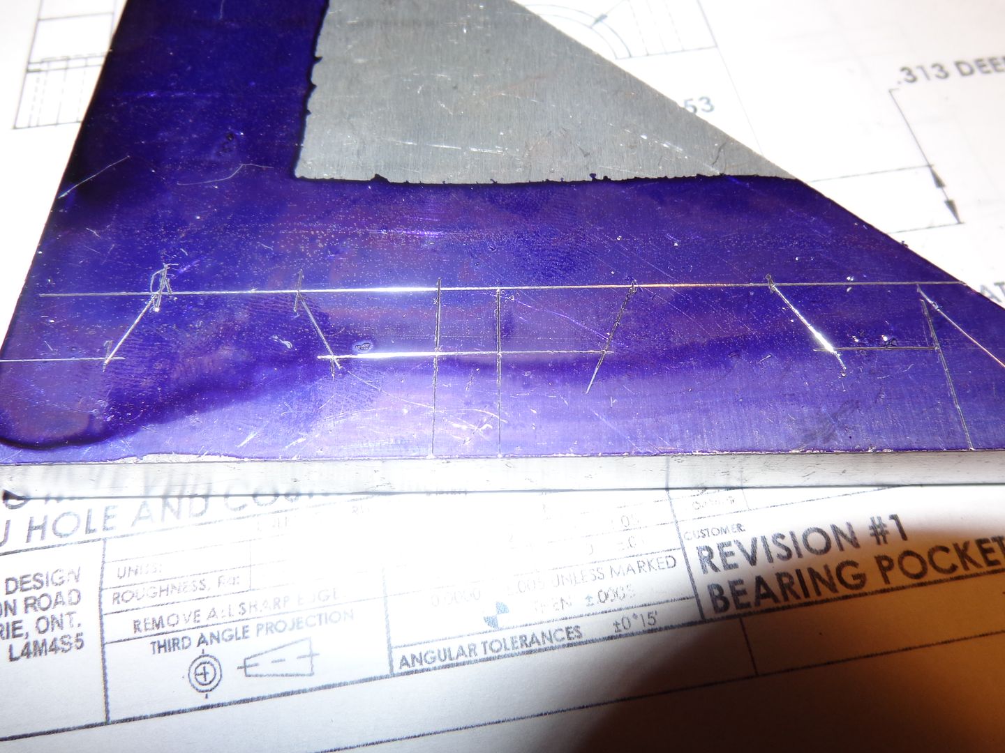
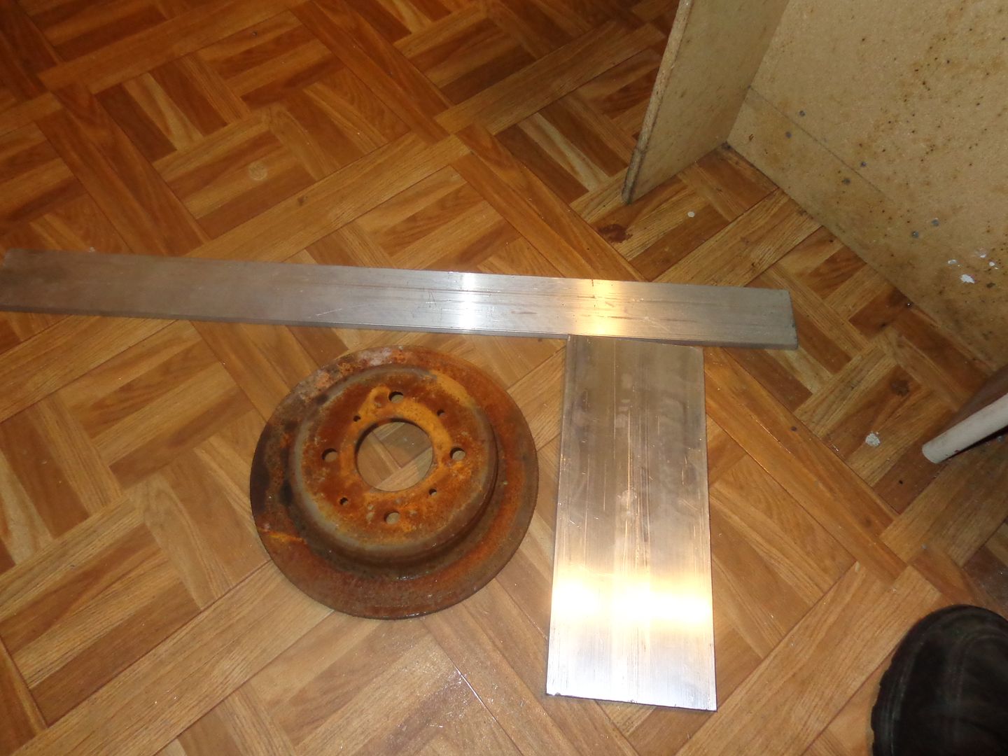
Got up this morning at 6:30 to a black, thundery looking day. I have orders from headquarters for only one thing today--"Go get a haircut--You're starting to look like a white haired Gollywog!!!"--Yes dear!!! This should leave the rest of the day to make parts. I have the layout dye on some aluminum for my bearing caps, waiting for it to dry. Have to go downtown and buy materials for baseplate and sideplates later this morning.--Will do that when I go to get "ungollywogged". Dye is dry--Have to go and make chips!!!
Go for it!!!Many thanks for your reply Brian - I didn't want to offend you.
Lol, I'm just an old tart when it comes to engines
I was thinking of pocketing some of the faces of the side pieces and head to give the appearance of cast in ribs, with radiused corners. What do you think?
Rivergypsy
Well-Known Member
- Joined
- Oct 15, 2010
- Messages
- 432
- Reaction score
- 222
Lovely job - I'll get busy on SW first thing Monday. I think the Interact should be free next week too 
canadianhorsepower
Well-Known Member
- Joined
- Oct 22, 2011
- Messages
- 1,671
- Reaction score
- 324
canadianhorsepower
Well-Known Member
- Joined
- Oct 22, 2011
- Messages
- 1,671
- Reaction score
- 324
Hi Brian
I was having a look at all the drawing yesterday
and I'm questionning myself about the crank shaft it self.
The picture shows one nut on each side. Is one of them lh thread
and one rh thread. If not I think we are in hot water:fan:
what do you think. my worry is that one will always get loose
I was having a look at all the drawing yesterday
and I'm questionning myself about the crank shaft it self.
The picture shows one nut on each side. Is one of them lh thread
and one rh thread. If not I think we are in hot water:fan:
what do you think. my worry is that one will always get loose
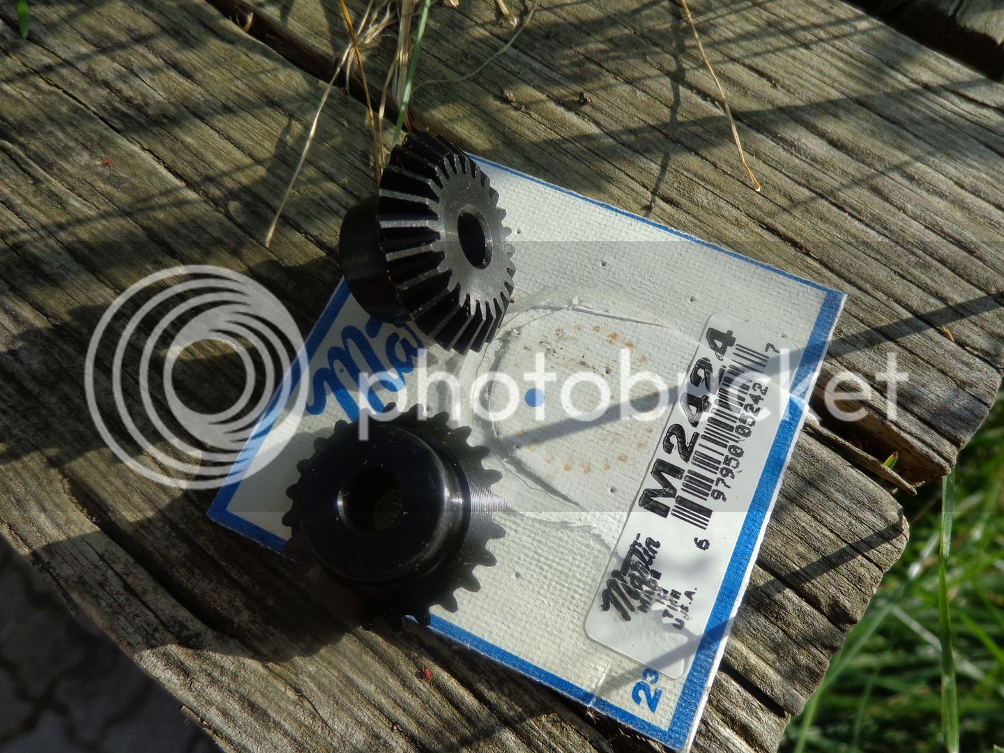
No, they are both right hand thread. I may modify that cross shaft and put a flange on one end that connects to the flywheel with four #8 socket head cap screws. The bevel gears are 24 DP X 24 TEETH x 1/4" bore. x 1" Pitch (I will open the bores up to 3/8".)Hi Brian
I was having a look at all the drawing yesterday
and I'm questionning myself about the crank shaft it self.
The picture shows one nut on each side. Is one of them lh thread
and one rh thread. If not I think we are in hot water:fan:
what do you think. my worry is that one will always get loose
Last edited:
canadianhorsepower
Well-Known Member
- Joined
- Oct 22, 2011
- Messages
- 1,671
- Reaction score
- 324
Cogsy
Well-Known Member
1inch pitch
PCD or Pitch Diameter I believe.
Yet PCD or pitch circle equals Number of teeth divided by DP 24/24 = 1
Similar threads
- Replies
- 28
- Views
- 4K
- Replies
- 27
- Views
- 3K
- Replies
- 61
- Views
- 8K


