pro-e-geek
Member
- Joined
- Mar 2, 2010
- Messages
- 8
- Reaction score
- 1
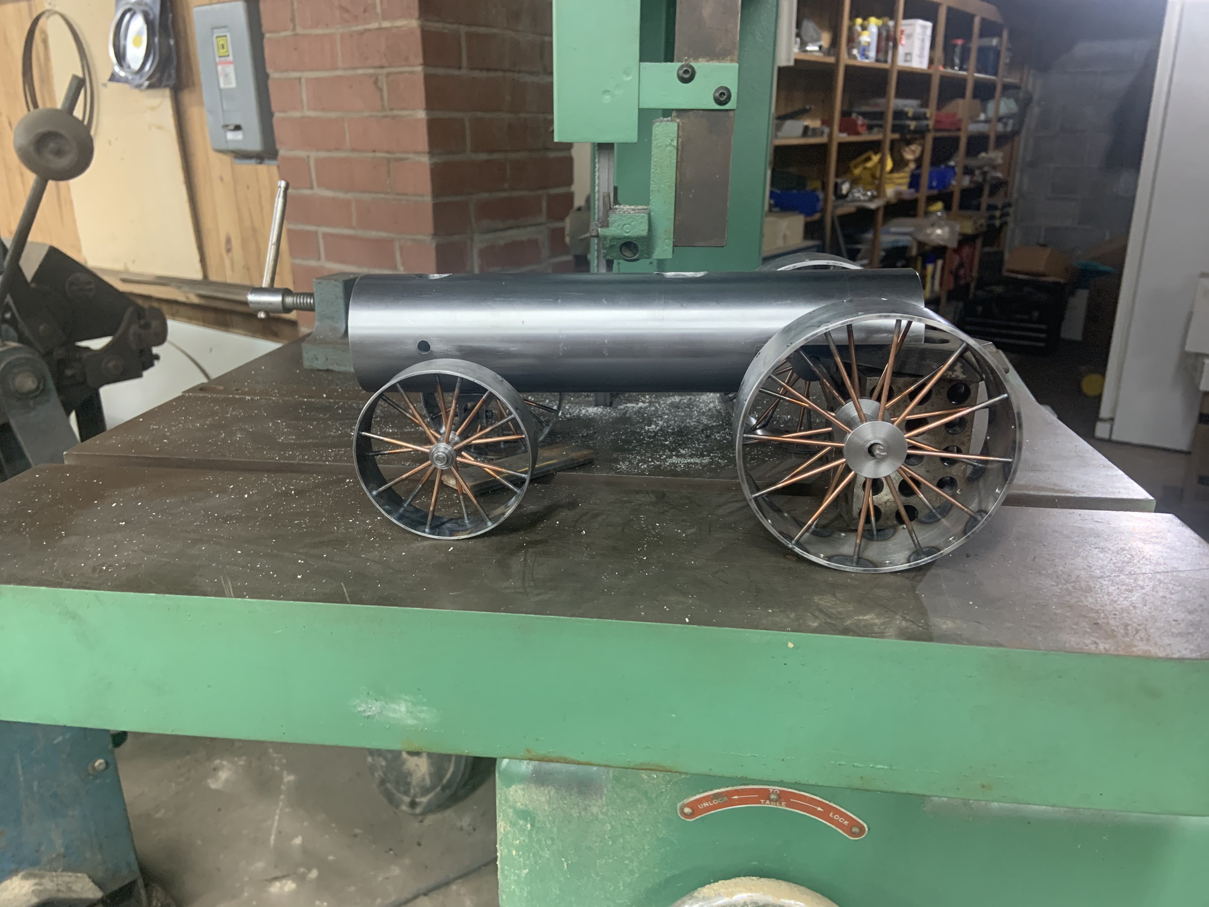
Well, it's been almost a year in recreating a Pro-Engineer CAD model of Rudy's engine from
his original hand drawn plans. (An hour here, 2 hours there & then put away when trout season started up..)
I took this project on for a couple of reasons, the first was that I needed an indoor winter project, & the second was that I wanted to figure out how to create moving mechanisms with the software. I definetly got a better handle on the mechanism part, but got a little hung up with getting the eccentric motion to work out. (I think the CAD model has more HP than my computer does.)
Rudy was a master, his drawings were beautiful & it amazes me how well the fit & finish of his parts in the model are. (But I'm sure that some of you have followed some of the builds of this tractor on this forum or even built them in the past. (I only wish I could view the pictures in the forums for these, I'm "locked out" here at work where I read them during my lunch hour.)
I still need to take care of some details like maybe adding rivets, making the worm for the steering shorter & finish making the gear train run & anything else I missed, but I'm excited to have got this far.
Someday, I hope to have a couple machines & be able to build this, but for now, this is the closest I can get.
Thanks to a couple of you who sent me pictures of his original engine in the past, I'm sorry I don't remember your names off the top of my head, but many thanks,
I've attached an image, I hope it goes through,
Any comments welcome,
John