Rotary Valves in the head?

Home Model Engine Machinist Forum

Help Support Home Model Engine Machinist Forum:

This site may earn a commission from merchant affiliate links, including eBay, Amazon, and others.

Mattkguns

Active Member
Joined
Sep 28, 2012
Messages
31
Reaction score
5
hey guys,

Had an idea, not sure if its been done elsewhere or not.

use valves in the head that rotate instead of moving up and down.

heres a picture of my idea drawn in inventor

Screenshot18.png


Let me know what yall think

also, assuming i continue to design a motor around this, how should i size the spark plugs?

Matt

edit: five seconds of searching later ive seen commercial versions of this product, such as
1rotaryvalve1.jpg

and
pic06.jpg
 
Hello Dansau

Very nice HP engine.
The cited economy contest sounds interesting .
Do You have a link, or is the US company still active?
How much is one of the 6 oz in gram and does somebody know the heating value of the contest glow fuel?
 
Valve arrangements in four strokes have been beaten to death. Only two valve types have had enough serious R&D to count as successful, the single sleeve valve and poppet valves. Sealing is the problem and poppet valves had that covered almost from the beginning. Lots of work went into that problem with the sleeve valves so they were becomming a contender for aircraft engines just before gas turbines took over. Poppet valves are so well understood and are such a part of the manufacturing process of engines that any other system is unlikely to be enough of an improvement to replace them.

That said, it's a lot more fun to build engines with unconventional valve systems in models. For as start check out sleeve valves (my favorite) here and here (use Google translate), and rotary valves here. You can see the huge number of unsuccessful tries to unseat (pun intended) the poppet valve.

Lohring Miller
 
Model airplane engines have used virtually all of the valve configuration ever dreamed up. Webra used rotary valves in their T-4 series. T4-40, T4-60 were a longitudinal rotary valve. The T4-80 had a Aspin valve.


HP VT-21


Webra T4-40

t4-80.jpg

Webra T-40

Cipolla_FS1.jpg
 
Have been fascinated by rotary valves and dreamed of inventing and earning a fortune.
My conclusion was that it is not realistic from emissions etc.
On the other hand I have not stopped dreaming of poppet valves that oppened the other way.That is oppening away from cylinder and of course it means holding it firmly during compression and combustion.
Advantage will be much better flow and easy to oil- cool valve and thus accept lower grade petrol.
If You can scheme and patent this lots of reward comes Your way.
 
thanks for all of the posts guys.

diesel pilot, i like that cipolla (i googled that image, and it led me back around to another of your posts on this forum) design, looks a lot like what i had in my head

so despite it not being as practical as i had thought, i get bonus points for coming up with it independently, right? ;D

so i might go ahead and design this. are there threads or other resources that would help with how big of valves for how much bore x stroke? also, for sparkplug sizes?
i think it would be fun to make a very high reving, very low load, model using this design.
use a short stroke and a larger bore. f1 style

im thinking .5" stroke, 1" bore. that would roughly be 2.5:1 with a flat piston, which is very low. what kind of compression should i aim for to achieve higher rpms?

Matt
 
The Aspin rotary valve will last longer. Easy to keep maintenance in case the Aspin rotary valve is not tight against leakage, also use chrome polish paste to lap the Aspin rotary valve against the cylinder head and the compression is back again. Not difficult to make the Aspin rotary valve by the model engine builder. ;)

The rotary valve in the bore is not easy to keep tight against leakage if the bore or rotary valve is worned out and need a new sleeve pushed into the cyliner head and adapt the rotary valve in the sleeve in the cylinder head.

It is my knowledge about the rotary valve since i am owner of the Webra T-4 with aspin rotary valve (0.87 cu/inc) :)
 
That is a good call mechanic boy, if i planned to put this into a working condition, i would likely go with that style valve.
As it stands here, though, im designing this motor as a stand motor. i imagine id put a low pitch prop on it to move air.
im hoping it would break 15k rpm, 30 if im being ambitious Thm:
the only load it would see would be said fan and a tach.

Matt
 
I only saw one valve before I posted. Then, I saw the second valve. To make a lot of power I expect to have several iterations. You basically try to make valves as large as possible, while still fitting everything.I think that if you want to run this type of engine for any period of time or power level the materials, fits, and finish have to be just right. I have a Webra T4-60 that loses compression after it warms up. I haven't checked what the problem is yet.

Niels, I also love sleeve valves. I have had the Barr & Stroud from SIC drawn in CAD for a long time, maybe this winter.

Greg
 
The problem with rotary valve is expanding by heat hence loss of compression. The expanding problem will be reduced by Aspin rotary valve.
 
hey guys,

Had an idea, not sure if its been done elsewhere or not.

use valves in the head that rotate instead of moving up and down.

heres a picture of my idea drawn in inventor

Screenshot18.png


Let me know what yall think

also, assuming i continue to design a motor around this, how should i size the spark plugs?

Matt

edit: five seconds of searching later ive seen commercial versions of this product, such as
1rotaryvalve1.jpg

and
pic06.jpg
The second photo is of a Coates Spherical Rotary Valve conversion for the 5.0 Ford engine. Designed by George Coates. He use to sell these conversions for engines ranging from the 5.0 Ford to Mercedes to helicopter engines to Big Rig Diesels to Harley-Davidsons. In fact,he had for a short time,his own motorcycle called the Coates Signature Series motorcycle.

He now is only interested in selling his design to big auto and diesel companies.

Example of benefits of his cylinder head design...On a stock 260hp 5.0 out of a Lincoln MK7 LSC,his conversion netted 480hp,and had practically zero emissions.(his claims).
 
Mercedes did try this concept, but results were not so great. Engine can rotate more freely and valve gear takes less power to work, no spring forces etc, but long run rotating valve loses all sealing possibilities. Carbon from combustion did brakes surfaces to rotate and seal correctly. This I read few years ago, from car magazine, so no direct link to source.
 
HP makes a .21 rotary valve engine. They used to make a .49, but I don't know if they still do.

I had a .21. When it was running, the only thing I could hear was the propeller. No exhaust noise at all. They had about as much power as anybody else's .15.

The good thing was the valve shielded the glow plug from the incoming fuel, so It stayed hotter.

http://www.mecoa.com/hp/vt/21.htm

RCV makes a .58 engine that has a rotary cylinder that works as the valves, I believe. I have one of those I got from a friend, but haven't spent any time with it and don't remember the theory of operation.

Steve Fox
 
I've been looking at rotary valves on IC engines for a while, mostly to avoid making cams without a CNC or even a mill. Another thing I ran into with that search is rotary sleeve cylinder valves. Seems they were used on very expensive cars years ago. Used oil, but ran very quietly.


Sent from my iPad using Model Engines
 
I ran across this post a couple of days ago.
It caught my interest because I'm considering trying to build a rotary sleeve valve engine. I'm probably biting off more than I can chew as I'm kind of fresh to machining, but nothing ventured...:rolleyes:
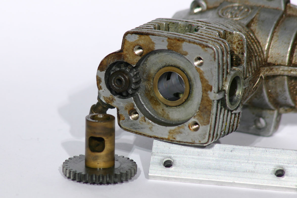
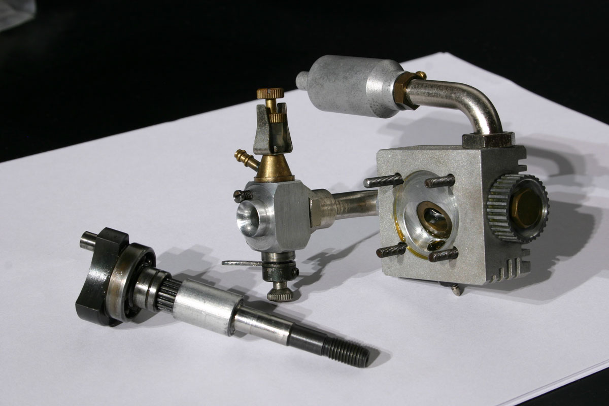
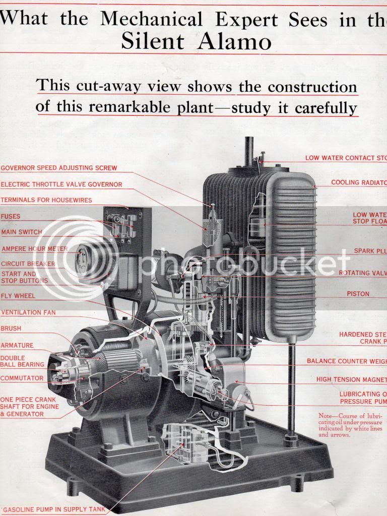
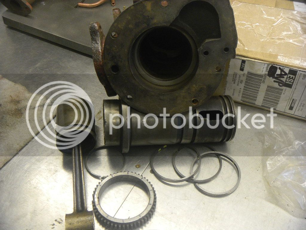
I have an early (1917) full size Alamo Electric Co. rotary sleeve valve engine which is currently partially disassembled to repair a broken tooth on the gear that drives the sleeve.
I'm not at all thinking of making a scale model of the entire unit, which is a 32 volt light plant.


But rather, try to incorporate the sleeve valve and it's associated gearing into a horizontal side shaft design using the plans for my 1 1/4" bore Wyvern.
I've made some preliminary sketches, basically to make sure I could end up with a reasonably sized gearing to accomplish the 4:1 drive ratio for the sleeve.
The Alamo is 2 1/2" bore and should readily scale into half size which is ideal to fit into the size of the Wyvern.

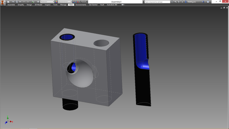
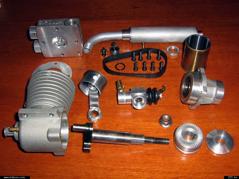
The sleeve has two ports/slots that are directly opposed to each other at 180 degrees. The timing is accomplished by way of rotating past two ports (intake and exhaust) and the spark plug, all spaced evenly 120 degrees apart. Giving the engine one power stoke per two revolutions of the crank, making it a four cycle engine. Each port takes turn functioning as either spark, exhaust or intake. It should prove interesting if I can pull it off.


I've been searching to find info on rotary sleeve valving and haven't yet found anything quite like this.
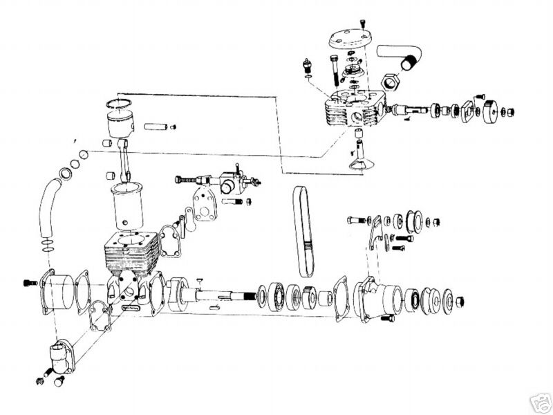
I'm considering air cooled as water cooling seems to lend itself towards a cast cylinder. There are other issues, as the Alamo also appears to use crankcase oil to partially cool the closed top of the sleeve above the top ring. The return oil passage passes thru the lower water inlet from the thermosyphon water cooling tank, which suggests this may require a pressurized oil supply to the sleeve.

A note of interest is that the 1KW Silent Alamo runs at whopping 2000 RPM, which is pretty durn fast for engines of this era.

Although this engine seems to be fairly simple, I really have to think this out more thoroughly before I start cutting any metal..:confused:

It also occurred to me that this timing concept should possibly work with a rotating disc in a cylinder head, but that would kind of take the fun out of it.

GUS
 
Last edited:

Latest posts

Back
Top