Everyone to their own Rod, and if you can work with it in one direction, then fine.
The problems arise Rod when you need to cut slots that maybe travel backwards and forwards half a dozen times. In your situation, you will have to lift the cutter, advance however many degrees to the start of the slot and start cutting again, repeat as required. For making things like flywheels, it is perfect as you get no over-run, a thing I used to suffer from when making them on a manual RT.
As I said, each to his own, I only raised the point because it really is a thing that needs to be done if you are searching for repeat accuracy with your RT or dividing head. I haven't as yet modded my dividing head, but it will be done, eventually.
If you don't eliminate that backlash you will forever be restricted to one accurate direction only.
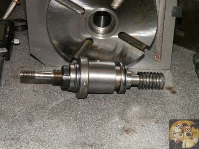
The inner shaft on my Vertex with sintered bearings is at most 0.001" end float, just enough to allow the shaft to rotate without binding, and on the AE ones, no end float at all, as they use roller bearing thrust washers and it can all be adjusted out.
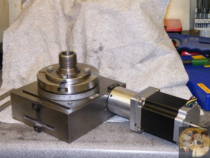
On the second one I showed, the high priced Arc Euro one, that is almost exactly the same mod done by AE on their 4th axis CNC RT's, but I use mechanical fixings on the stepper coupling tube rather than a Loctite approach.
http://www.arceurotrade.co.uk/Catalogue/Workholding/Rotary-Tables/4-Rotary-Table-with-Stepper-Motor
For the extra couple of hours machining and the few bucks it takes to do the mods, it is well worth it in the knowledge that you have an RT that can be used accurately in both directions without having to turn back and move forwards again to eliminate your backlash and get to where you were in the first place.
John


 Can we talk a little about division plates? How do I determine how many to buy,and which ones I will be needing? Also would a four jaw Chuck be better option than a three?