Rotary table -Divider plates

Home Model Engine Machinist Forum

Help Support Home Model Engine Machinist Forum:

This site may earn a commission from merchant affiliate links, including eBay, Amazon, and others.
Status
Not open for further replies.

Brian Rupnow

Design Engineer
Project of the Month Winner
Joined
May 23, 2008
Messages
14,961
Reaction score
8,236
Location
Barrie, Ontario, Canada
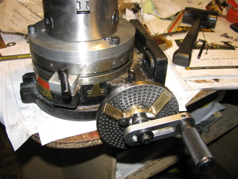
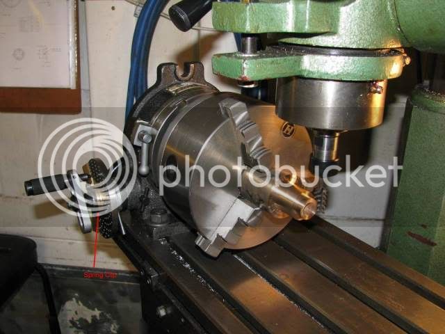
Today I washed all the cosmoline gunk off my Divider plates which came with my rotary table (which I purchased 3 years ago). I followed the Chinglish instructions, and after slotting the holes in the divider plates so they would actually fit the bolt pattern in the rotary table (Thats a whole 'nuther story) I was able to assemble things okay. I am beginning to figure out how the divider plates are supposed to work---fortunately I am using the rotary table to cut an eithteen tooth gear, which means 5 full rotations of my handle to accomplish the 20 degrees between cutting positions, so I can use any of the divider plates. (Mine is a 90:1 gear reduction).----Now the question---Those brass arms (I think they are called "sectors") have a screw, which when tightened will lock the angle between the sector arms---However, the two arms (now locked at some angle) seem to rotate fairly freely on the center hub.---They shouldn't do that, should they?? If I am doing some exotic pattern that calls for X number of full rotations and then count how ever many additional holes in the divider plates to let my spring loaded handle pin drop into (Which I THINK is supposed to be located by one of the sector arms)---and the arms rotate out of position---then I'll end up dropping my spring loaded pin into the wrong hole. What am I not understanding here???---Brian
rotarytablewithdividerplates001.jpg
 
Brian,

In the dividing plate set there is a largish spring clip which locates in a groove in the shaft and prevents the sector arms from rotating freely. They will still rotate as they must but with some resistance.

Looking at your picture you seem to have it fitted but maybe it needs bending to tighten things up a little.

IMG_1225S.jpg


The pin should be inside the sector arms and the sector arms should be set to the number of holes required + 1. e.g. X turns + 10 holes, the sector should be set to 11 holes on the appropriate holes circle.

Hope this helps

Best Regards
Bob
 
Thanks Bob---I guess mine must be okay then. they don't "flop around" but if you weren't paying attention when you were turning the handle and the pin did hit them, they would move. I guess that just means "Pay attention"!!!----Brian
 
Hi brian i have a whole book just on dividing if you would like to borrow it just let me know.
 
Brian;
I will try to help if I can.

The two arms should rotate freely around the hub but not too freely.

On my RT there is a half moon spring between the arms and the hub that keeps tension between the two.
If your divider plates don’t have a spring, thy are very easy to lose or it may have came without one you mite be able to put a peace of paper or even some tape between the arms and the hub to give you the friction you need. Or you may be able to dill & tap the ring on the arms for a small set screw to give some friction.

On the divider plate you mite want to put a mark on the top of the plate at the hole that you will be using with something like a Sharpie pen so you will know where you are. When going around the plate for the next tooth if you should go by where you want to stop, you will want to take a full turn in the opposite direction to get red of any back lash then come back to where you wish to be.

You don’t want any distractions, it is very easy to lose count and end up ruing a gear. Cutting gears can be enjoyable (and at times almost as much fun as watching oil base pant dry) Ha, Ha.

Good luck
Richard
 
Gee Brian, I thought you said you weren't interested in learning how to use dividing plates.

Let me see if I can explain the use of the sector arms.

With a 90:1 RT, you have to turn the RT handle 90 full turns to make the part turn one complete revolution. Now let's suppose you want to make a 21 tooth gear. That requires turning the part 1/21 revolution for each tooth. That means you have to turn the handle

(1/21) * 90 = 90/21 = 4 & 6/21 turns

for each tooth. That's four complete turns of the handle and 6 spaces (note I didn't say holes) on the 21 hole plate.

Put the pin in one of the holes and bring the beveled edge of one of the sector arms around to touch the left side of the pin. Now, counting the hole the pin is in as zero, count off 6 holes and place another pin. Verify that there are indeed six inter-hole spaces between the two pins. Bring the other sector arm around so its beveled face touches the right side of this last-placed pin. Tighten the locking mechanism that retains this angular separation of the two arms.

Now, when you want to index, swing the locked sector arm assembly so as to put the beveled edge of the sector arm pair against the left side of the indexing pin. Pull the pin and turn it 4 full turns, then continue to the hole that lies next to the other sector arm on the 21 hole ring. Voila, you've moved the handle 4 and 6/7 turns and you only had to count to four. Really, once you understand it, I think you'll agree that it's a very ingenious mechanism.

-----

For any other gear, with N teeth, simply compute:

90/N

and express it in a fraction with a denominator that matches the number of holes in one of your hole circles. Then proceed as above to set the sector arms.

-----

If you do a lot of dividing, it's still easier to use my program. Or, use it to check your calculations if you have concerns.
 
Marv---Thank you. I really, really didn't want to use the dividing plates. They seemed like such a black mystery to me that I was afraid to use them. However---once I read enough to realize that with 20 degree seperations I could use any of the plates, not worry about the sector arms, and "hole counting", I decided to at least see if they would fit on the rotary table. Of course, the damned things didn't, and had to be modified, but they are on there. ---Now you have to realize---I was terrified of computers too---Swore I would never use one.---Now I teach 3D solid modelling. I guess anything is possible.---Brian
 
It's far simpler than it might appear from a casual glance and it's a valuable tool to have in your arsenal. All that's required mathematically is a bit of diddling with mixed fractions. The rest is simple mechanics and will be obvious.
 
I just found this really neat video on "That other" website I hang out on. Its great---shows a man making a gear and using the dividing plates and sector plates. Make sure your sound is on when you watch it.
[ame]http://www.youtube.com/watch?v=VHTXaU7GZC0[/ame]
 
  • Like
Reactions: gus
Brian Rupnow said:
and after slotting the holes in the divider plates so they would actually fit the bolt pattern in the rotary table (Thats a whole 'nuther story) I was able to assemble things okay.

Yes my instructions were a bit vague on assembly too and it took me nearly 2 hours to fit the plates correctly on my first use. :big:
I haven't used mine very much yet and I need to concentrate when I am using it not to mess it up, but I do love them
 
Nice video. Thanks for the link Brian. That made it look simple.
 
Oh great explanation! I learnt it 35 yrs back and now forgot. But you opened up my old files.
Thank you
 
Thanks for jogging my memories to 1962 when I was taught to use divider plate to cut a 4" spur gear.
Now I can remember how the spreader arm is used. Classmate preferred to count the holes and skip using the spreader arms
and end up with a spur gear with half tooths.:hDe:He got chewed up by the same instructor who gave us theory lesson.:hDe:
 
Now that I have used my set up enough to get friendly with it, I find it works very good. I just recently cut my first set of 45 degree miter gears. There is one bit of simple black magic that I always use. It doesn't matter if I'm making a simple gear that doesn't require any partial turns of the crank, (thus requiring the sector arms) or not.--Use a black "magic marker" to draw a circle around whatever hole (or holes) you are using. that way, even if you do "bump" the sector arms and move them, its a simple thing to put them back to where they should be. The marker rubs off with a bit of paint thinner or layout dye remover.---Brian
 
We are back in the UK again- if only for much larger problems than 'Simple Division'. Life for many of us is not sector arms but whether real arms will ever rotate again.
Sorry, but I have mentioned many times where readable information is. Perhaps the cheapest is- if you can afford the paper and the ink- and time to down load is A H Smith's Advanced Machine Tool Work which contains so much information that most of the questions asked here would be even more repetitive. If you want to go the whole hog there is little to beat George Thomas's Workshop Technique's or the earlier print of his Dividing and Graduating. All been in Model Engineer in the past and our old associate Dr Bill Bennett hacked it into a book from the articles following George's illness and then death.

So if you want to know 'how it all works' rather than how to protect machine tools from scratches- that's the way.

Me? I have the classic division plate- with a single hole it.
 
No Sour Grapes intended but I cannot see how anyone can condense useable information into such a space. Now I have a homemade Versatile Dividing Head to GHT design with the ability to create 'any division' as well several sizes of rotary tables -both home made and bought out.
As a very young Goldstar, I had charge of a technical library of with 5 staff and quoting the Gypsy (Queen 71) engine bit there was inches thick books merely on that engine alone and the Antarctic Gypsy's for the Auster 7's were another item altogether and so on.
Years later, I did a British City And Guilds in Motor Vehicle Restoration( for kicks) but it was all of 4 years and with loads of written work.

Frankly, I cannot understand how anyone can 'do' engineering involving one liners in what has to be a correspondence course.

Sorry but I can't.

Regards

Norman
 
Speaking for myself, virtually all the info I have learned in 'engineering' has been from this site alone. While I would not trust any of my 'work' in a production or commercial environment, I have learned to create working model engines from chunks of raw materials. This is a hobby for the majority of us and life and limb doesn't rest on the outcome of our endeavours, merely enjoyment.

As long as I can find out, or work out, how to get a particular machining process done to my satisfaction, I don't see the need for a university eductaion into the theory behind it, nor the industry 'best practice'.

If I can be frank - if you can't see the point or worthiness of a forum such as this, then why do you bother to come here?

My apologies if I have caused offence, it was not my intent.
 
Goldstar--We are not ignoramuses on this site. We design and build some fairly exotic machinery. We also have or have access to technical libraries that are pertinent to what we have to know. On the corner of my desk is "Gears and Gearcutting" by Ivan Laws. I have a couple of "Workshop Practice" series books outlining the basics of using a milling machine and a lathe. I have "The Machinery Handbook" 23rd edition. I also have "Handbook of Mechanical Engineering" by Beitz and Kutther. I have "The Handbook of Dimensional Measurement: by Farago. I have "Engineering Drawing and Design" by Jensen. I have "Canadian Professional Engineering Practice and Ethics" by Andrews and Kemper. I have "The Law and Business Administration" by Smyth, Soberman, and Eason. I have "Marks Standard Handbook for Mechanical engineers" by Avaland and Baumeister. Pretty well every one of the builders on this forum does a goodly amount of research before setting out on a project. I have built 12 running steam engines , six internal combustion engines, and a multitude of mechanical devices to run with my engines. I have 50 years of building race car engines and professional drag racing behind me. ---Brian Rupnow
 
Status
Not open for further replies.
Back
Top