Home Model Engine Machinist Forum

Help Support Home Model Engine Machinist Forum:

This site may earn a commission from merchant affiliate links, including eBay, Amazon, and others.

RobConway

Well-Known Member
HMEM Supporting Member
Joined
Jan 2, 2021
Messages
50
Reaction score
132
Location
Australia
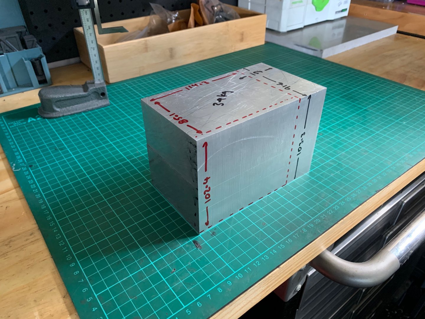
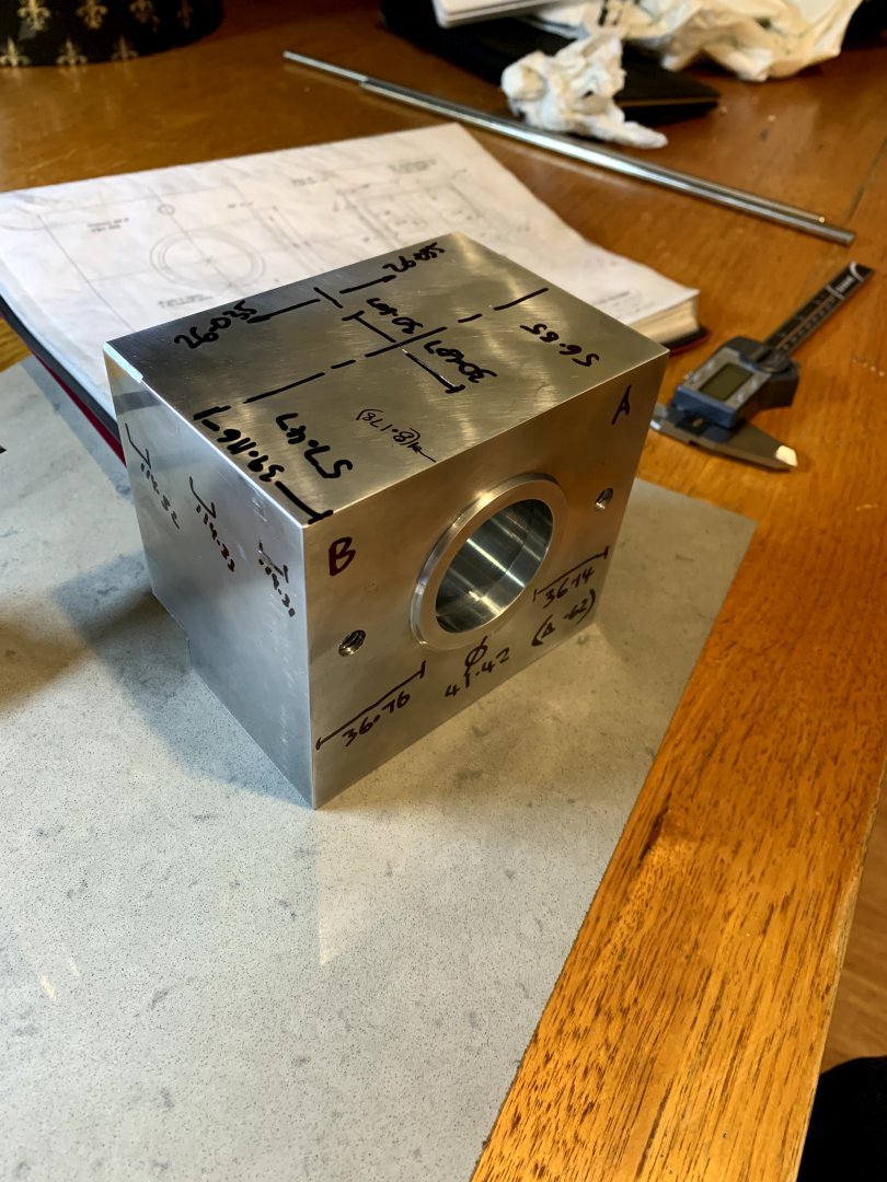
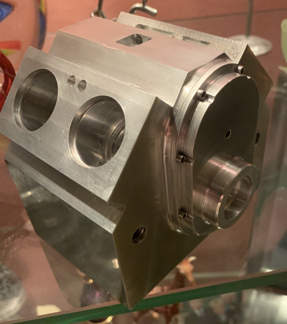
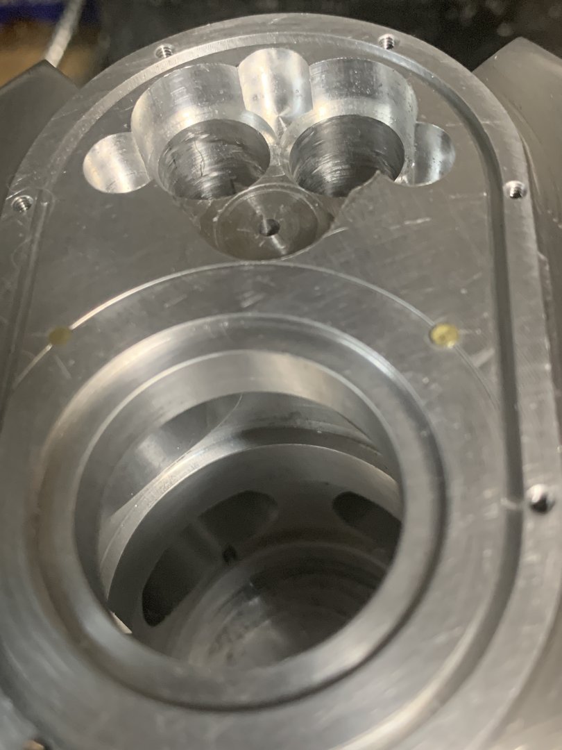
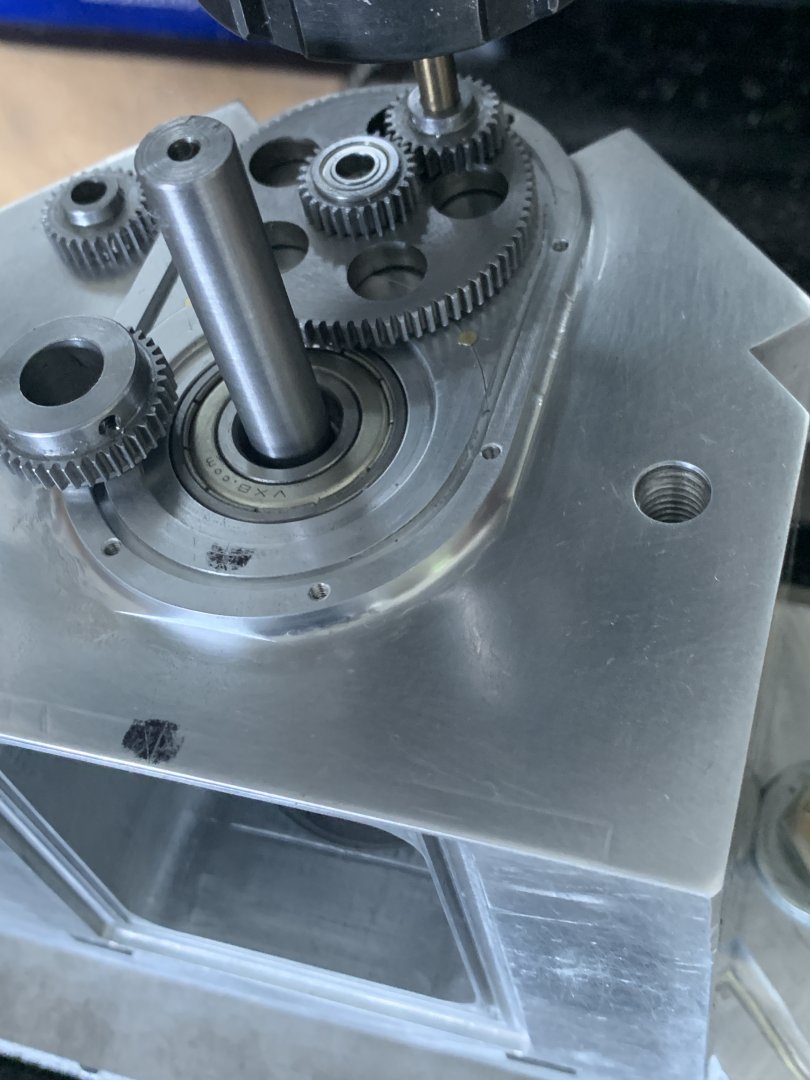
So for someone who did machining in the 80's as part of an apprenticeship, built one steam engine in 2019, take on a Jerry Howell V4 ? Better not answer that as it is very optimistic / naive I will admit , especially when it seems every single tolerance is soo critical. I must be 150 hours invested so far and probably 80% the way through the machining of the block. I thought if I can complete the block the chances of being able to complete the engine may just be achievable over the next few years. Although shipping of parts and imperial tooling and gear cutters has been costly shipped to Australia so I am kind of financially committed now. A couple of pics on where I am up to...... Next step I am going to make one crankshaft (flywheel end) to make 100% sure of the gear mesh between the timing gears before committing to the camshaft locations.
 

Attachments

  • IMG_2458.jpg
    IMG_2458.jpg
    165.7 KB · Views: 329
  • IMG_2473.jpg
    IMG_2473.jpg
    104.3 KB · Views: 313
  • IMG_3106.jpg
    IMG_3106.jpg
    139.5 KB · Views: 317
  • IMG_2985.JPG
    IMG_2985.JPG
    102.4 KB · Views: 316
  • IMG_3131.JPG
    IMG_3131.JPG
    113.1 KB · Views: 329
Last edited:
Had a test run on drilling the 1/2” cam shaft holes on a scrap piece I practise on before committing to the real thing. Purchased a long 5mm jobber drill and then went through with the 1/2”. Setup seems ok so next weekend will commit to the cam shaft holes and gear CB detail at the flywheel end of the block.

I also purchased one if those cheap sand blast guns AUD $ 30.00 even came with some grit. This is a pic of a 20-30 second sand blast on my test piece. Also interested to see it didnt erode the narrow edge where i practise drilling the 3” long camahaft.

I like this “cast” looking finish which I will do the sides of the block once complete instead of painting it. I was really happy about how the grit removed the machining marks.
 

Attachments

  • 4F3CAA80-B298-4273-A20C-8061F962278F.jpeg
    4F3CAA80-B298-4273-A20C-8061F962278F.jpeg
    189.6 KB · Views: 177
The test hole went soo well and clean. Today the final cam holes didnt do as well, maybe the speed was too low and didnt clear the swarf anyhow now have two 1/2" holes and the bearings drop in and locate OK. Overall the dimensions seem to be comming all together which is my biggest relief.
 

Attachments

  • IMG_3171.JPG
    IMG_3171.JPG
    96.7 KB · Views: 220
  • IMG_3162.JPG
    IMG_3162.JPG
    114.6 KB · Views: 225
Last edited:
Oh Dam, Guess who did not indicate vertically the gear cover position based upon the two circle centres... When I made a gear cover I never squared up the blank as everything machined from the two centres. So when I came to align the gear cover on the end of the block I stupidly used a square against a non parralel side which also seemed to align to the top of the block, which was incorrect. Anyhow understanding a noob mistake, looks like I have to take 0.7mm off one side of the head so I can locate the valve lifter bush. I am concerned that the push rods will not be the same dimension from the pivot of the rocker arm, which I assume means one side the valves will open more than the other. I made a plug so I can see where the lifter needed to be drilled at 45 degrees to the centre of the camshaft. I might have to offset the rocker arm brackets or was also thinking I could offset drill the lifter bushing and have a smaller diameter valve lifter whereby I could recover say 0.25mm in a few places to get better alignment on the right hand hand shaft. On the left cam I could drill the pushrod bushing on a slight angle to compensate and get the pushrod aligning back to the rocker.
 

Attachments

  • InkedIMG_3182_LI.jpg
    InkedIMG_3182_LI.jpg
    114.1 KB · Views: 224
Last edited:
The easiest fix would be to change the rocker arm dimension and its pivot point. The right Cam is going to be the opposite issue it being further away from the pivot. There got to be an easy fix ? or compromise, is it really going to matter for an engine that will never see any real load ? What do you think of the fix below, offset bracket pivot and make the rocker arms to new dimension as long as they pivot in the center (well loks like there is a 2% leverage effect .445 ver .455


1638017956210.png
1638019725014.png
 
Last edited:
Thanks @gbritnell , I went ahead and drilled the lifters and all holes in the head. Exciting part next weekend in machining the rest of the block away to reveal the "V" :) I did a quick pic and I assume the actual contact point between the cam/lifter probably doesn't shift and the contact point moves from center on the face of the lifter.
1638134117827.png
 
Flywheel weekend. Found a nice 3/8-24 nut at the auto shop which is actually a head stud bolt, has a star head similar to (but not) torx. Made a colar around it with a three point dog. I will put a pin between the collar and flywheel to stop it undoing the nut when starting. I didnt have 3” steel round however did have a slice of brass nearly the right size and aluminium. So just made the brass 10% smaller than the steel flywheel to account for weight and did an aluminium collar as didnt want a shiny brass flywheel. So thats the backend done :)
 

Attachments

  • 114C3B8C-1FF6-428F-A4E4-D0C0A936C096.jpeg
    114C3B8C-1FF6-428F-A4E4-D0C0A936C096.jpeg
    122.4 KB · Views: 172
  • 45BEDAE5-D6FC-49F9-9022-B16973A3B5E2.jpeg
    45BEDAE5-D6FC-49F9-9022-B16973A3B5E2.jpeg
    199.8 KB · Views: 169
Last edited:
Not much happening over the last few weeks however have completed the two heads. I think I have learnt something about my DRO. I used ABS and INC reference to set the two zero points for each head, as I was machining them from one piece. The last operation of machining the two valve holes on the last head I was moving the table at the same time as I changed over from ABS to INC. The DRO lost about 0.4mm. Luckily it is just slightly offset vertically so just compensated with the sparkplug hole a little higher. Seems there is some tollerance as it should still fit within the inside diameter of the valve sleeve.
Next on the list is the valve guides and then for something different may start the radiator and mounting rails.
 

Attachments

  • howell head.png
    howell head.png
    469.4 KB · Views: 168
Last edited:
wow, this is going to test my patience, the first radiator tube messing around with setup took me 3 hours. Not much deformation of the fins although at first, I thought the fin itself was 0.040" and then realsied its .026" !

Anyhow now I understand stock length and how to best hold it (I set it up at full 4" length between an er32 collet in the chuck and a centre). I printed out the accumulative 60 measurements (for each fin) set the DRO and then went about cutting. Luckily I had a parting tool (1.0 mm) that has a T shaped cutting edge and the top of the tool has a groove. I dont think I could of ground a parting tool to this accuracy.

Another 7 tubes to go.... and hopefully I can get it down to less than an hour per completed tube.
 

Attachments

  • radiator tube.jpg
    radiator tube.jpg
    209.2 KB · Views: 181
  • radiator stock.jpg
    radiator stock.jpg
    211.3 KB · Views: 183
Last edited:
For reference this is the blade used from an australian supplier having USA stock and ended up running at 750 rpm. Cutting from the chuck to tailstock was better and did not cause any noticable displacement of the adjacent fin. I might get a few more blades of differnt sizes as the profile and top surface recess did make parting a breeze.

still took 1.5 hours per tube

& yes i may of trashed my er32 18mm collet however did hold the square stock very easily. The drilled through hole (drilled 2” from each end) turned out perfect where the hole met up inside, so the tollerance was very acceptable. I do have an MT4/er32 arbour to replace the chuck altogether however this hex er32 adapter I simply used to test the concept did so well didnt bother changing it over .
Have purchased some silver paste solder and arrives next week to finish off the radiator.
 

Attachments

  • 1B9343EC-E030-4E9E-B8F6-CB85FBB4FF4B.jpeg
    1B9343EC-E030-4E9E-B8F6-CB85FBB4FF4B.jpeg
    157.6 KB · Views: 154
  • 52E03332-5474-4ED4-B466-A64D3DC7EF5C.png
    52E03332-5474-4ED4-B466-A64D3DC7EF5C.png
    477.5 KB · Views: 166
Last edited:
Didnt know what the policy was for supplier details. the url is in the top of the pic though as took it from my phone :)

As I have no real training, sharpening any tool is a challenge in term’s of understanding optimal angles however with the profile of these its easy, and worth the fact they are 3x the cost
 
Last edited:
Nervously waiting for the silver solder paste to arrive to complete the radiator. Looks like I better get fusion360 fired up for the radiator support brackets and dust off the CNC router which will be good for the engine mounting skid and rad supports. I will enjoy seeing these items being made on the cnc instead of the manual mill, albeit it will probably take me a couple of hours to sketch them up and create the gcode..
 

Attachments

  • 86B2C777-4DEB-4F11-ACAB-6B496A9DF982.jpeg
    86B2C777-4DEB-4F11-ACAB-6B496A9DF982.jpeg
    220.9 KB · Views: 126
Last edited:
@scooby I gotta get my software sorted. The dam Fusion360 personal use version does not convert mesh to solid object and is limited on import file formats. I was looking at a solidwork lic for $~50 / year for personal use. Maybe I should change software although just got the hang of the fusion CAM settings. What are poeple using ? My CNC uses Mach3
 
I have never made Brass name plates before so thought why not give it a try. Although as I do not have access to a laser printer I purchased some transfer paper from a local electronics shop which is used to make PCBs which stated laser or photocopier. So printed some Howell logo's out using a photocopier and ironed it onto some 1/16" brass plate. The etch has gone 60 minutes in warm ferric chloride I should probably finish it up however thought I will give it another 30 minutes. The Howell stencil which come with the plans had very very thin characters which did not transfer that great so simply chose a font and did my own for now. As you can see in the pic the toner has stayed on quite well. & yes Ill remeber to stick it on the front of the radiator :) I do really like the Howell "red" however think I will simply be different and go blue.
 

Attachments

  • howell xfer.jpg
    howell xfer.jpg
    114.1 KB · Views: 164
  • howell etch.jpg
    howell etch.jpg
    104.4 KB · Views: 174
  • B16240C5-21DF-415B-A4F1-AB60231C4662.jpeg
    B16240C5-21DF-415B-A4F1-AB60231C4662.jpeg
    371.7 KB · Views: 181
Last edited:

Latest posts

Back
Top