Richard Horne
Member
- Joined
- Dec 4, 2008
- Messages
- 15
- Reaction score
- 12
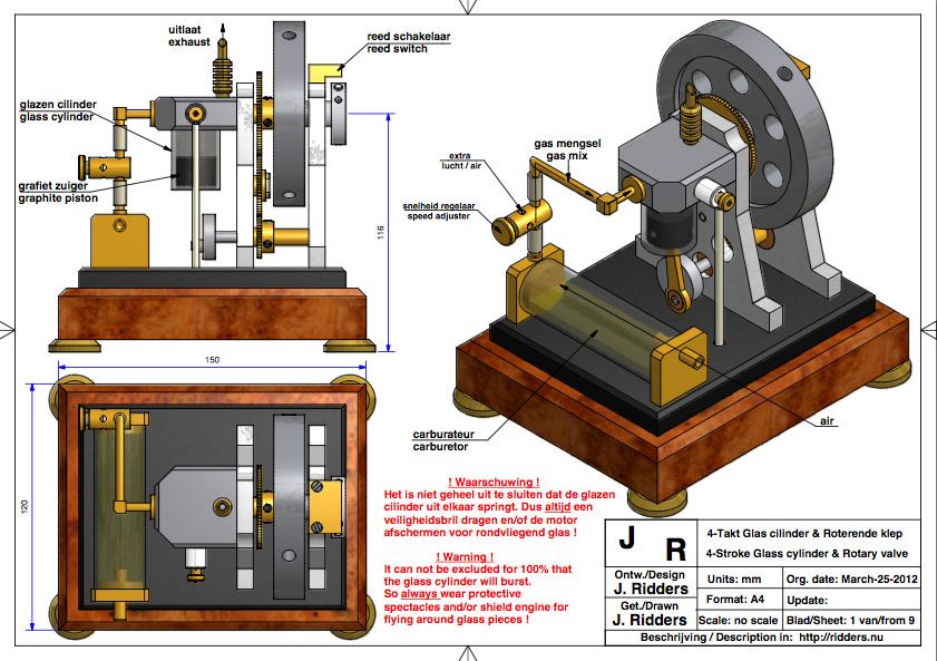
For my first internal combustion engine model, Ive decided to build Jan Ridders one cylinder glass 4 stroke engine. Plans, pictures, and videos of the finished engine can be found at Mr. Ridders web site. The engine uses a single glass cylinder making combustion visible, a rotary valve built into the cylinder head and turned by the flywheel, and a simple carburetor that operates by airflow over a fuel reservoir.
This is an ingenious little engine that is simple enough for my first IC project. It will be a good match to my small shop and my current capabilities. Of course the unique feature is the glass cylinder that allows combustion visibility, which will be a great hit with grandkids. Also, I expect this to be a very clean running engine. The bearings are sealed, and the glass cylinder with graphite piston requires no lubrication at all. Instead of gears between the crankshaft and flywheel I will use toothed wheels and a timing belt that require no lubrication. The only lubrication required will be a drop of oil now and then for the rotary valve within the cylinder head. So even though this is an open crank design, I hope there will be a minimum amount of oil flinging about.
American Adaptations: The original design is metric; so a few adaptations are useful when building the model in the United States. First, I will use the closest match UNC fasteners rather than the specified metric fasteners. I already have a large inventory of these fasteners from past projects, so switching to metric seems unnecessary.
I will use toothed wheels and a timing belt instead of gears between the crankshaft and flywheel. I see this as a simplification. Only two axles are required, and nearly infinite combinations of these drives are available from on-line suppliers.
The flywheel axle and crankshaft are specified as 6mm and 5mm diameter respectively. I plan to use ¼ inch stainless precision shafting instead, which simplifies construction of the shafts and makes for easy selection of bearings.
And finally, I plan to use a simple single spark electronic ignition of which several models are available from on-line suppliers. This will replace the original design using a modified circuit from a hand held Blokker spark lighter that is hard to find in the United States.
THE GLASS CYLINDER
Where to Find the Glass Cylinder: I decided to first face the task of cutting the glass cylinder, and the fist step here is finding a source for the specified 20 mm diameter syringe made from borosilicate heat resistant glass. The plans specify a Fortuna-Optima 20 mm glass syringe and give directions to the Sigma-Aldrich manufacturer web site. However, I found the Sigma-Aldrich web site to be distinctly unfriendly to individuals attempting to buy this syringe. There is a barrage of intrusive questions about your company, your title, and your plans for safekeeping and storage, followed by the statement Due to the nature of products, every new online customer must be reviewed If we are unable to complete approval, we MAY contact you for further information. I bailed out of the web site at this point and went to eBay, where I found used syringes for sale in just a few minutes. I have checked back with eBay several times since, and these syringes are nearly always available. It is important to obtain interchangeable model syringes since this guarantees that the inner diameter has been very accurately ground to a specified size.
Cutting the Glass Cylinder: Ive had some previous experience cutting glass test tubes when I built one of Jan Ridders glass Stirling engines. See my Stirling Engine article. Although I finally succeeded in cutting and finishing the required Pyrex tube by hand scribing, breaking along the scribed line, and hand sanding, my success rate was never better than about 25%. Obviously, I need a near 100% success rate now that I no longer have a vast supply of inexpensive tubes to work with. So I decided to take the plunge and build a precision tube cutter. The design for such a cutter can be found at the bottom of Jan Ridders internal combustion engine page, here. It consists basically of a horizontal carriage that can be moved a few thousandths at a time toward a spinning diamond wheel. The diamond wheel is powered by a Dremel rotary tool and is cooled during cutting by a slow water drip.
My version of a precision tube cutter is shown below. Ive made several changes to the original design. The carriage is extended to the left to better support cuts of longer sections, the open kerf in the carriage is widened to allow cutting off the wide upper lip of a large syringe, and instead of a water tank reservoir, cooling is provided via components of a slow drip plant watering system that connects to a standard one inch garden hose via a ¼ inch plastic tube and inexpensive pressure regulator. It actually only took a few days to put this together, and it has completely solved the problem of reliable glass tube cutting. The base is made from a plastic cutting board; the carriage is made from a bar of acetal plastic, and most other mounting components made from scrap aluminum. The drive consists of toothed wheels and a timing belt from Stock Drive Products.
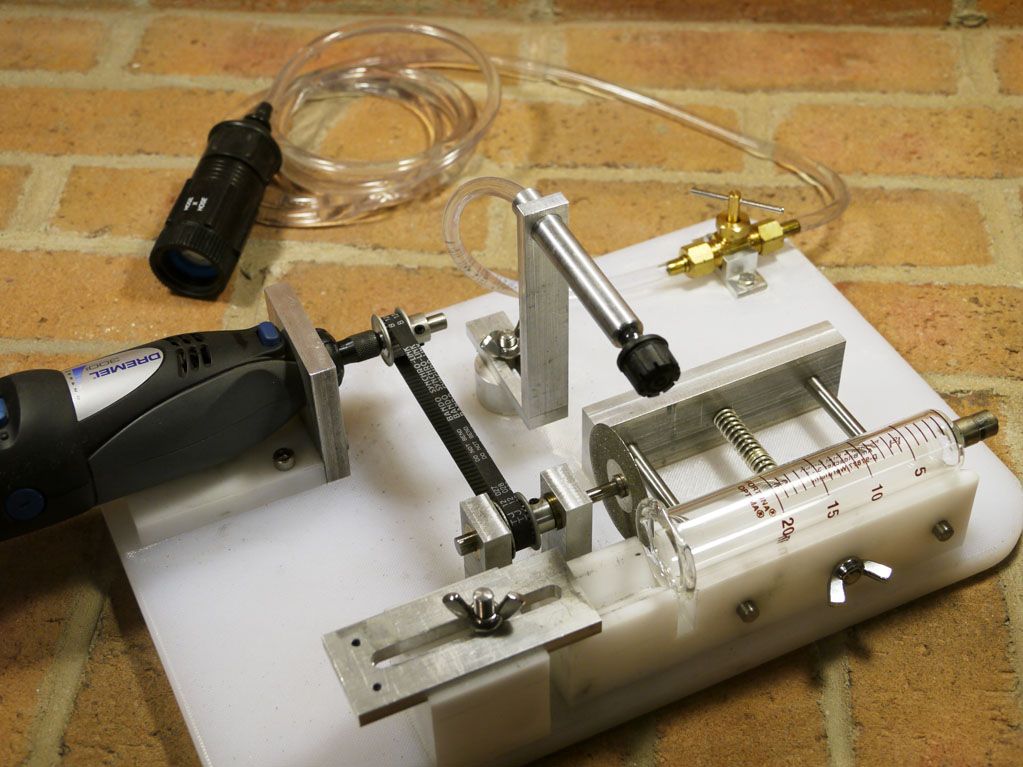
A stainless steel axle and simple brass bearings were used to support the diamond wheel. If I were doing this again I would use sealed bearings instead. The inner bearing is constantly splashed over by the cooling water drip. This tends to wash away bearing lubrication after 10 or 15 minutes of use, and I did have one instance of this bearing freezing up due to poor lubrication.
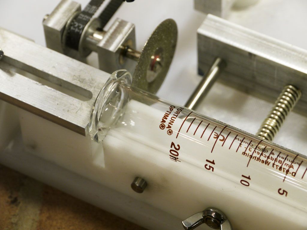
In operation, the wheel is set spinning at a high rate, the drip is set at about two or three per second, and the tube is turned slowly by hand against the rotation of the diamond wheel while the carriage is advanced at a few thousandths per step. At each step, the tube is turned manually through a complete rotation. Advancing in this way, it takes only a few minutes to make a clean cut through the tube wall.
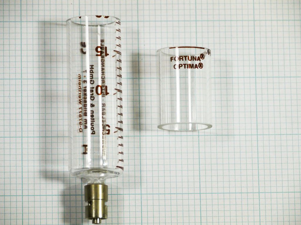
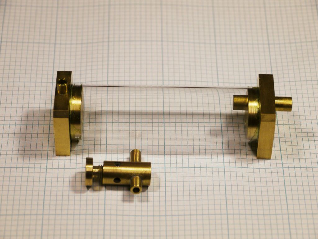
Two cylinders could be cut from a single syringe. However the upper section has fewer printed words on the glass, so this is the section that I have chosen to use. After completing the cuts, I finished the cylinder ends with a fine 400 grit diamond hand pad to make them completely smooth and chip free.
MECHANICAL PARTS
Support Columns and Base: The support columns and engine base are made from 8mm and 10mm aluminum plate respectively. I milled down 3/8 and ½ inch aluminum plate to obtain the raw material for these parts. Obviously, this also means finishing a large surface area of flat aluminum plate. I dont strive for a mirror finish, but I do want to eliminate visible tool marks. I have done such finishing in past projects by hand using emery paper on a flat surface plate. However the area to be finished here is vastly larger and is impractical to finish by hand. This gave me an excuse to buy a 4 inch by 36 inch belt sander for my shop, which completed the finishing very quickly.
One caution about inexpensive belt sanders is that the plate over which the belt runs is not a machined surface and may not be flat. In my case, the plate was stamped steel and was about 5 thousandths concave at the center of the 4 inch width. The predictable result was that my initial finished surfaces were about 5 thousandths convex at the center. This doesnt seem like much but it can be a problem when the surface must be flat for mounting other components. I spent a few hours with a large mill file to flatten the belt plate on the sander before proceeding.
The support columns themselves are an attractive shape made with both vertical and sloping sides. I suppose it is theoretically possible to have milled these shapes manually using my mini mill. However, I found it much easier to make up the columns from three sections a rectangular bar at the bottom, a trapezoidal middle section, and a square top section. These sections were then fastened together with close fitting pins and Loctite.
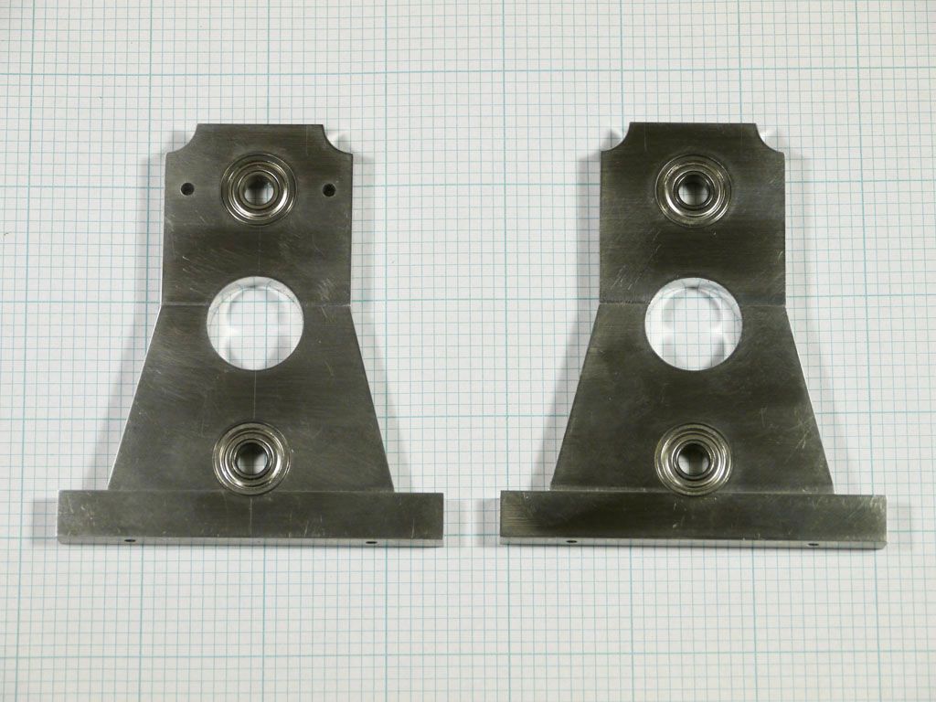
Shown above are the finished columns with inserted bearings. I believe that the angles around the column are much crisper in appearance than I could have achieved by milling the columns manually in one piece using my mini mill.
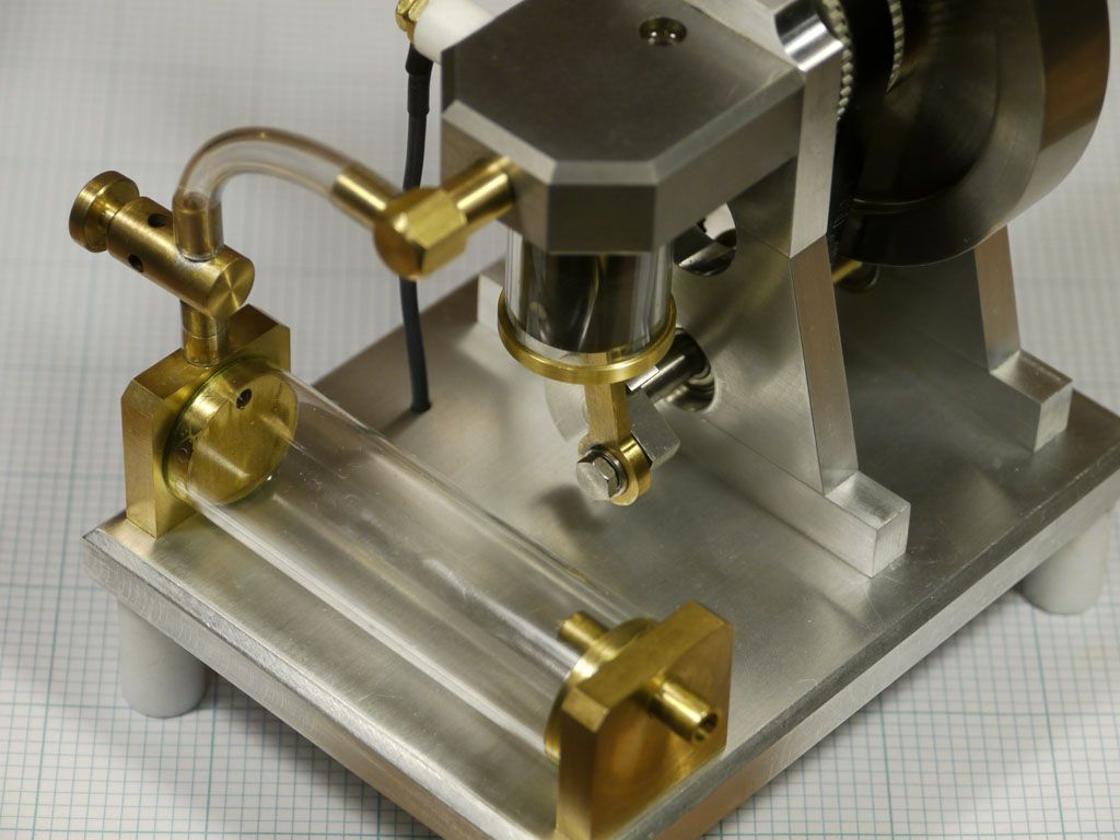
Cylinder Head: The cylinder head is relatively straightforward and was machined from a one inch thick slice of two inch square cast iron bar. Shown below is the completed cylinder head with valve openings at the top of the cylinder for fuel and exhaust and a spark plug socket. Also shown is the rotary valve itself, which is a rotating hollow rod of cast iron with separated internal sections for fuel vapor and exhaust. The flywheel turns the rotary valve in its tube just over the top of the cylinder.
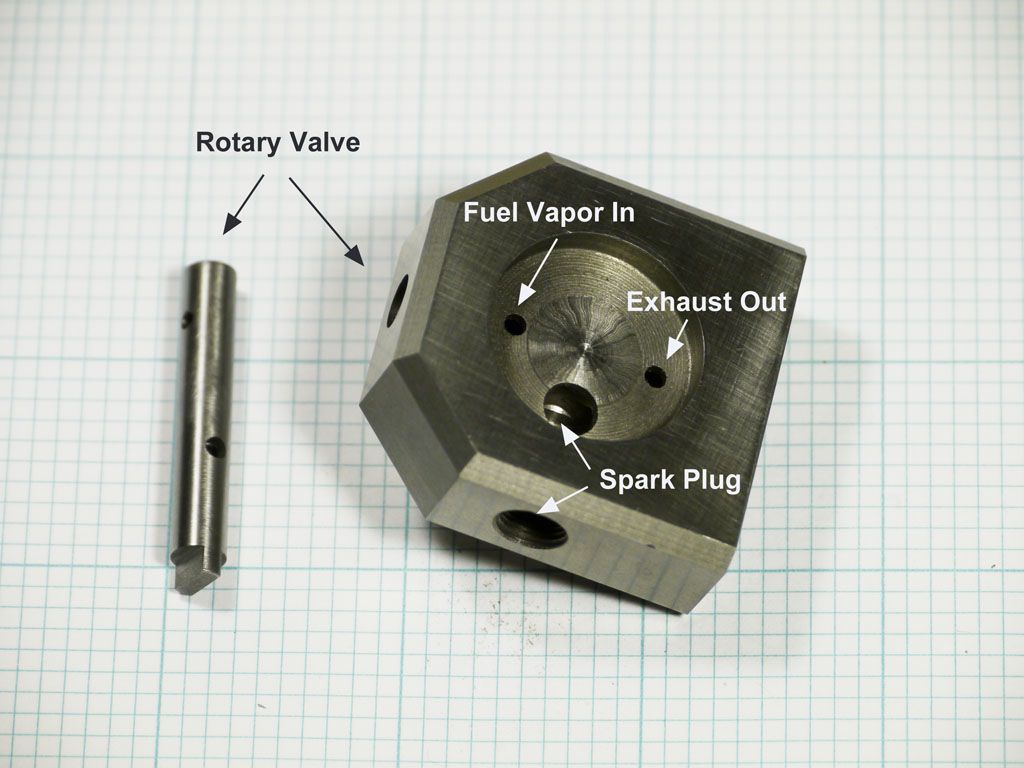
The rotary valve is simple in design but a bit tricky to build. The fuel and exhaust ports must be precisely spaced and must be precisely 90 degrees from each other. I found that a small rotary table mounted horizontally on the bed of my mini mill was invaluable for placing these ports correctly.
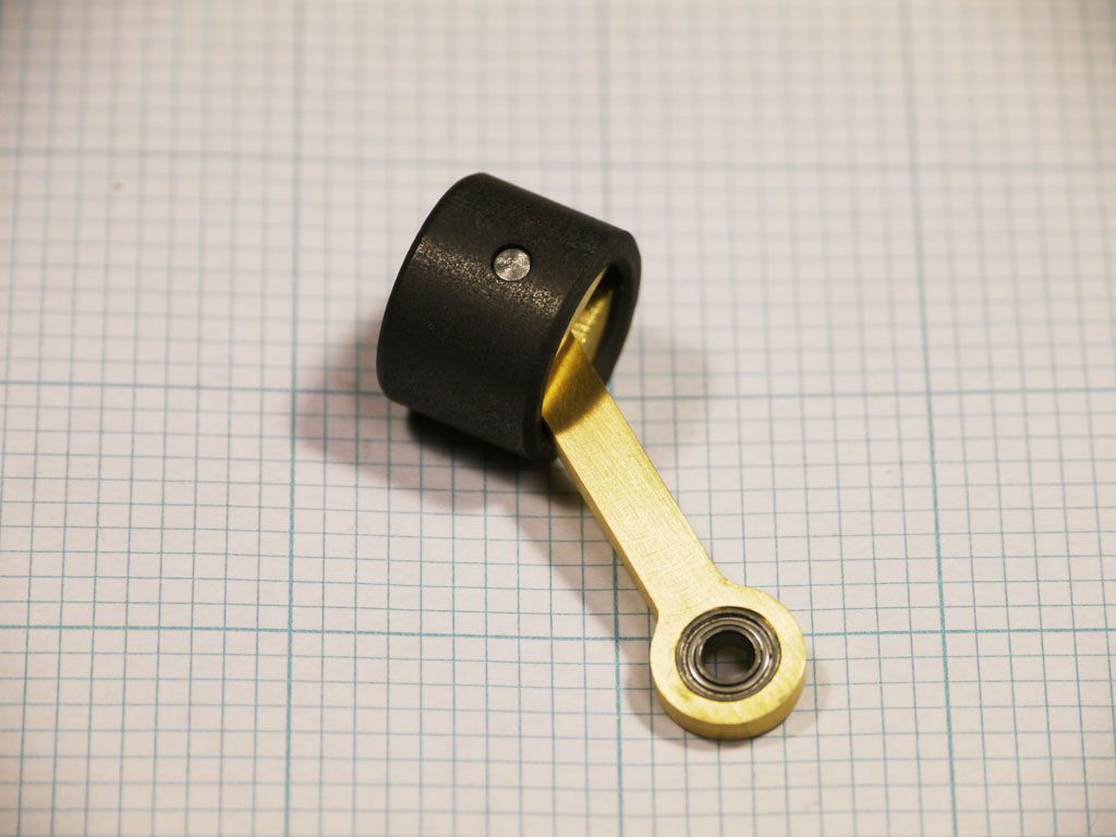
The Flywheel: I machined the 90 mm flywheel from a one inch thick slice from a 4 inch diameter bar of cast iron. SpeedyMetals.com was a lifesaver here in that they can provide 1 inch cuts from large diameter cast iron bar for a reasonable cost. Shown below is the finished flywheel with its hub and mounted toothed wheel.
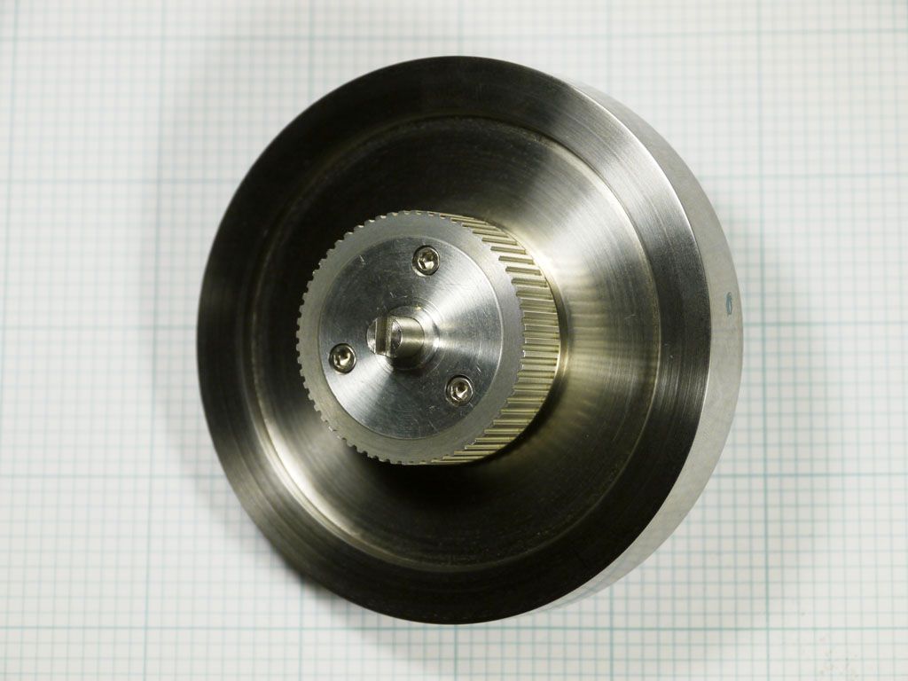
Im using a ¼ inch stainless steel precision shaft with this flywheel, and I know from experience that a large flywheel attached to a relatively small shaft will often exhibit an unsightly wobble. To prevent this from happening, I initially machined the flywheel about 20 thousandths oversize in diameter and thickness. I then inserted a hub and axle and machined the final diameter and thickness with the flywheel mounted on its actual axle.
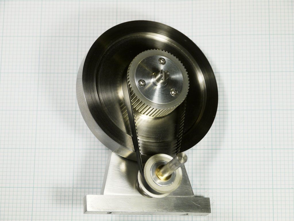
Toothed Wheels and Belt: My initial plan was to use toothed wheels without flanges for the timing belt, mainly because I thought these just looked better. I believed I could machine the column bearing mounts to provide almost perfectly parallel axles so that the belt would not gradually drift off of the wheels. It turned out that my machining was precise enough, but the belt itself apparently has a slight warp so that it will drift one way or another by reversing the belt. This was the highest quality urethane belt with Kevlar cords that I could find online, so I must conclude that a slight warp in any of these belts is to be expected. My solution to the problem was to use a flanged wheel for the crankshaft axle at the bottom position and keep the flange-less wheel on the flywheel axis.
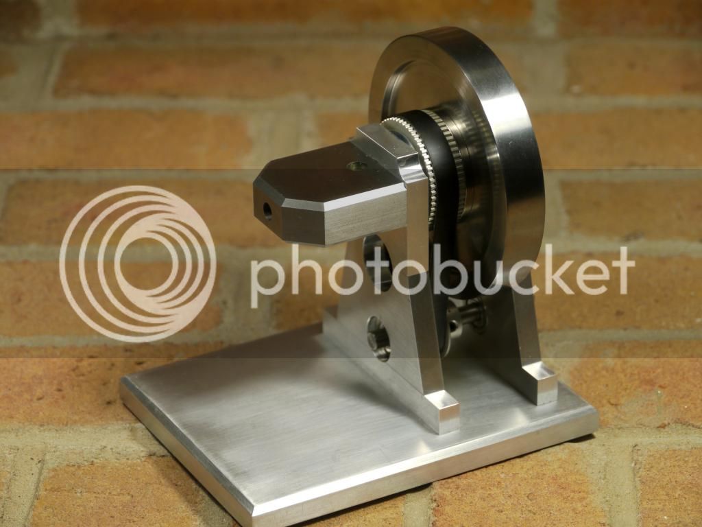
Progress To Date: Partial assembly of the columns, flywheel, toothed wheels, timing belt, and cylinder head is my state of progress on this model as of mid November 2014. This glass cylinder has been cut and finished, but not yet mounted in the cylinder head. This represents perhaps 200 hours of work over 10 weeks time. Next I will be working on the piston and crank and the vapor carburetor. Ill save the entire subject of ignition for last.
This is a most enjoyable engine to build. It is perfect for my small shop consisting of about 75 square feet crammed with an 8.5 inch lathe (SIEG SC4 from Little Machine Shop), mini mill (SIEG X2 from Grizzly), and RIKON 4 inch belt sander. As usual, Jan Ridders design is ingenious and the drawings are precise and clear. I expect that I will be enjoying this project most of the winter season.
Additional motivation for those interested in this engine can be found in this video.
[ame="http://www.youtube.com/watch?v=dRaqPULZL_Q#t=31"].[/ame]
This is an ingenious little engine that is simple enough for my first IC project. It will be a good match to my small shop and my current capabilities. Of course the unique feature is the glass cylinder that allows combustion visibility, which will be a great hit with grandkids. Also, I expect this to be a very clean running engine. The bearings are sealed, and the glass cylinder with graphite piston requires no lubrication at all. Instead of gears between the crankshaft and flywheel I will use toothed wheels and a timing belt that require no lubrication. The only lubrication required will be a drop of oil now and then for the rotary valve within the cylinder head. So even though this is an open crank design, I hope there will be a minimum amount of oil flinging about.
American Adaptations: The original design is metric; so a few adaptations are useful when building the model in the United States. First, I will use the closest match UNC fasteners rather than the specified metric fasteners. I already have a large inventory of these fasteners from past projects, so switching to metric seems unnecessary.
I will use toothed wheels and a timing belt instead of gears between the crankshaft and flywheel. I see this as a simplification. Only two axles are required, and nearly infinite combinations of these drives are available from on-line suppliers.
The flywheel axle and crankshaft are specified as 6mm and 5mm diameter respectively. I plan to use ¼ inch stainless precision shafting instead, which simplifies construction of the shafts and makes for easy selection of bearings.
And finally, I plan to use a simple single spark electronic ignition of which several models are available from on-line suppliers. This will replace the original design using a modified circuit from a hand held Blokker spark lighter that is hard to find in the United States.
THE GLASS CYLINDER
Where to Find the Glass Cylinder: I decided to first face the task of cutting the glass cylinder, and the fist step here is finding a source for the specified 20 mm diameter syringe made from borosilicate heat resistant glass. The plans specify a Fortuna-Optima 20 mm glass syringe and give directions to the Sigma-Aldrich manufacturer web site. However, I found the Sigma-Aldrich web site to be distinctly unfriendly to individuals attempting to buy this syringe. There is a barrage of intrusive questions about your company, your title, and your plans for safekeeping and storage, followed by the statement Due to the nature of products, every new online customer must be reviewed If we are unable to complete approval, we MAY contact you for further information. I bailed out of the web site at this point and went to eBay, where I found used syringes for sale in just a few minutes. I have checked back with eBay several times since, and these syringes are nearly always available. It is important to obtain interchangeable model syringes since this guarantees that the inner diameter has been very accurately ground to a specified size.
Cutting the Glass Cylinder: Ive had some previous experience cutting glass test tubes when I built one of Jan Ridders glass Stirling engines. See my Stirling Engine article. Although I finally succeeded in cutting and finishing the required Pyrex tube by hand scribing, breaking along the scribed line, and hand sanding, my success rate was never better than about 25%. Obviously, I need a near 100% success rate now that I no longer have a vast supply of inexpensive tubes to work with. So I decided to take the plunge and build a precision tube cutter. The design for such a cutter can be found at the bottom of Jan Ridders internal combustion engine page, here. It consists basically of a horizontal carriage that can be moved a few thousandths at a time toward a spinning diamond wheel. The diamond wheel is powered by a Dremel rotary tool and is cooled during cutting by a slow water drip.
My version of a precision tube cutter is shown below. Ive made several changes to the original design. The carriage is extended to the left to better support cuts of longer sections, the open kerf in the carriage is widened to allow cutting off the wide upper lip of a large syringe, and instead of a water tank reservoir, cooling is provided via components of a slow drip plant watering system that connects to a standard one inch garden hose via a ¼ inch plastic tube and inexpensive pressure regulator. It actually only took a few days to put this together, and it has completely solved the problem of reliable glass tube cutting. The base is made from a plastic cutting board; the carriage is made from a bar of acetal plastic, and most other mounting components made from scrap aluminum. The drive consists of toothed wheels and a timing belt from Stock Drive Products.
A stainless steel axle and simple brass bearings were used to support the diamond wheel. If I were doing this again I would use sealed bearings instead. The inner bearing is constantly splashed over by the cooling water drip. This tends to wash away bearing lubrication after 10 or 15 minutes of use, and I did have one instance of this bearing freezing up due to poor lubrication.
In operation, the wheel is set spinning at a high rate, the drip is set at about two or three per second, and the tube is turned slowly by hand against the rotation of the diamond wheel while the carriage is advanced at a few thousandths per step. At each step, the tube is turned manually through a complete rotation. Advancing in this way, it takes only a few minutes to make a clean cut through the tube wall.
Two cylinders could be cut from a single syringe. However the upper section has fewer printed words on the glass, so this is the section that I have chosen to use. After completing the cuts, I finished the cylinder ends with a fine 400 grit diamond hand pad to make them completely smooth and chip free.
MECHANICAL PARTS
Support Columns and Base: The support columns and engine base are made from 8mm and 10mm aluminum plate respectively. I milled down 3/8 and ½ inch aluminum plate to obtain the raw material for these parts. Obviously, this also means finishing a large surface area of flat aluminum plate. I dont strive for a mirror finish, but I do want to eliminate visible tool marks. I have done such finishing in past projects by hand using emery paper on a flat surface plate. However the area to be finished here is vastly larger and is impractical to finish by hand. This gave me an excuse to buy a 4 inch by 36 inch belt sander for my shop, which completed the finishing very quickly.
One caution about inexpensive belt sanders is that the plate over which the belt runs is not a machined surface and may not be flat. In my case, the plate was stamped steel and was about 5 thousandths concave at the center of the 4 inch width. The predictable result was that my initial finished surfaces were about 5 thousandths convex at the center. This doesnt seem like much but it can be a problem when the surface must be flat for mounting other components. I spent a few hours with a large mill file to flatten the belt plate on the sander before proceeding.
The support columns themselves are an attractive shape made with both vertical and sloping sides. I suppose it is theoretically possible to have milled these shapes manually using my mini mill. However, I found it much easier to make up the columns from three sections a rectangular bar at the bottom, a trapezoidal middle section, and a square top section. These sections were then fastened together with close fitting pins and Loctite.
Shown above are the finished columns with inserted bearings. I believe that the angles around the column are much crisper in appearance than I could have achieved by milling the columns manually in one piece using my mini mill.
Cylinder Head: The cylinder head is relatively straightforward and was machined from a one inch thick slice of two inch square cast iron bar. Shown below is the completed cylinder head with valve openings at the top of the cylinder for fuel and exhaust and a spark plug socket. Also shown is the rotary valve itself, which is a rotating hollow rod of cast iron with separated internal sections for fuel vapor and exhaust. The flywheel turns the rotary valve in its tube just over the top of the cylinder.
The rotary valve is simple in design but a bit tricky to build. The fuel and exhaust ports must be precisely spaced and must be precisely 90 degrees from each other. I found that a small rotary table mounted horizontally on the bed of my mini mill was invaluable for placing these ports correctly.
The Flywheel: I machined the 90 mm flywheel from a one inch thick slice from a 4 inch diameter bar of cast iron. SpeedyMetals.com was a lifesaver here in that they can provide 1 inch cuts from large diameter cast iron bar for a reasonable cost. Shown below is the finished flywheel with its hub and mounted toothed wheel.
Im using a ¼ inch stainless steel precision shaft with this flywheel, and I know from experience that a large flywheel attached to a relatively small shaft will often exhibit an unsightly wobble. To prevent this from happening, I initially machined the flywheel about 20 thousandths oversize in diameter and thickness. I then inserted a hub and axle and machined the final diameter and thickness with the flywheel mounted on its actual axle.
Toothed Wheels and Belt: My initial plan was to use toothed wheels without flanges for the timing belt, mainly because I thought these just looked better. I believed I could machine the column bearing mounts to provide almost perfectly parallel axles so that the belt would not gradually drift off of the wheels. It turned out that my machining was precise enough, but the belt itself apparently has a slight warp so that it will drift one way or another by reversing the belt. This was the highest quality urethane belt with Kevlar cords that I could find online, so I must conclude that a slight warp in any of these belts is to be expected. My solution to the problem was to use a flanged wheel for the crankshaft axle at the bottom position and keep the flange-less wheel on the flywheel axis.
Progress To Date: Partial assembly of the columns, flywheel, toothed wheels, timing belt, and cylinder head is my state of progress on this model as of mid November 2014. This glass cylinder has been cut and finished, but not yet mounted in the cylinder head. This represents perhaps 200 hours of work over 10 weeks time. Next I will be working on the piston and crank and the vapor carburetor. Ill save the entire subject of ignition for last.
This is a most enjoyable engine to build. It is perfect for my small shop consisting of about 75 square feet crammed with an 8.5 inch lathe (SIEG SC4 from Little Machine Shop), mini mill (SIEG X2 from Grizzly), and RIKON 4 inch belt sander. As usual, Jan Ridders design is ingenious and the drawings are precise and clear. I expect that I will be enjoying this project most of the winter season.
Additional motivation for those interested in this engine can be found in this video.
[ame="http://www.youtube.com/watch?v=dRaqPULZL_Q#t=31"].[/ame]
Last edited: