a--d
Member
- Joined
- May 26, 2014
- Messages
- 7
- Reaction score
- 7
Hi,
I've started building a Ridders Coffee Cup Stirling engine here in Yorkshire, England.
After spending a year turning a lot of metal into swarf and not really getting anywhere other than fixing a few things on the lathe itself I decided a proper project would be a good start.
I appreciate these LTD stirlings are quite difficult to get running but hey, if you're going to do something why not jump in head first? There is also an almost worrying level of coffee consumption by everyone both at home and work, so what better to start with?
I only have a lathe, no mill, so I was looking in particular for something that could be achieved simply within these limitations.
First I downloaded the plans from ProjectsInMetal a few months ago and started to remake them in Autodesk Inventor. This is so I can learn the software and get my head around the parts before making chips.
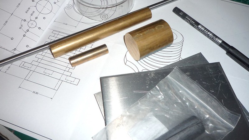
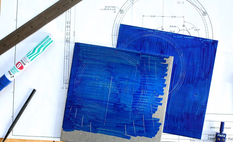
The plans call for 5 mm thick end plates, but these are being made from 5mm sheets. They might be a little thinner than intended. I'm sure that'll be fine as long as the internal volume of the displacer cylinder doesn't change too much, and that's controlled by the cylinder walls, a separate part.
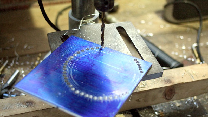
I don't have access to a bandsaw, so hacksaw it is all the way. I figured drilling around the edges would speed up the cutting process by removing most of the material for me. It did.
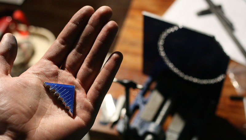
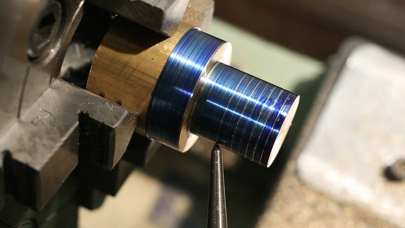
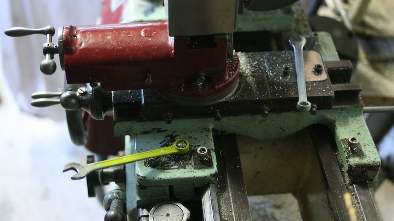
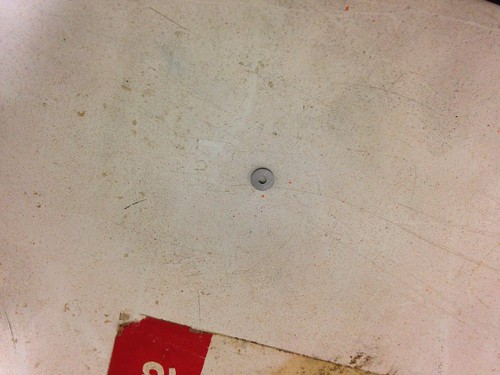
Once all the sections are cut out the jaggedy blank was super-glued to a large chunk of aluminium and very, very gently turned down to round with a bit of support from a live centre in the tail stock, a centre-drilled piece of scrap and an off-cut of some kind of anti slip matting from work.
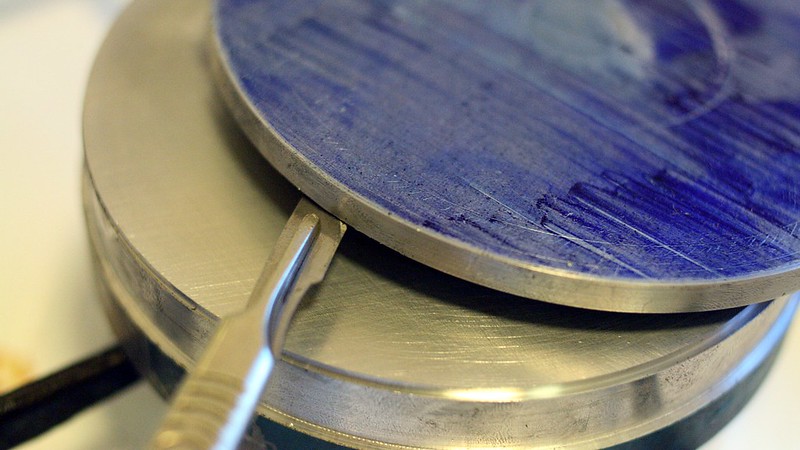
Gently heating the metal sandwich on the gas hob and prying with the blade of a scalpel separated the two pieces nicely, with the sacrificial blank ready to use again for turning the upper plate.
I'll do this in the future with the window open from the get-go - it smells really bad.
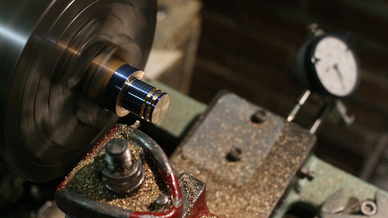
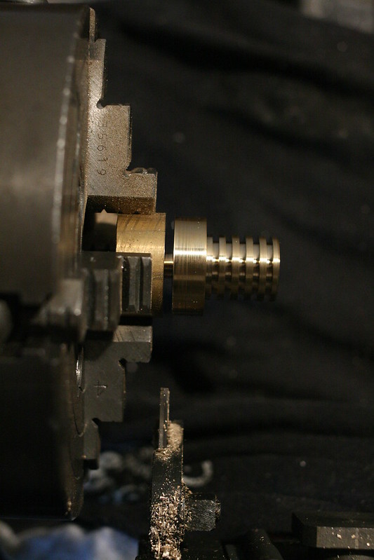
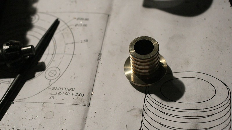
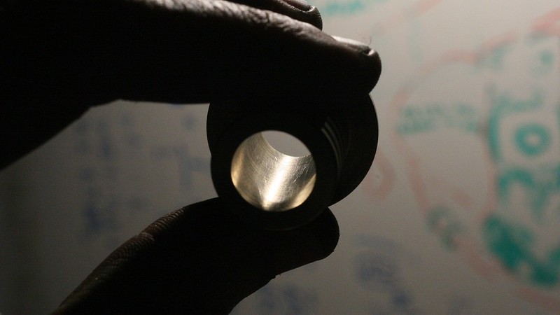
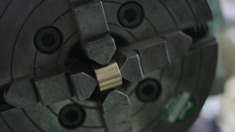
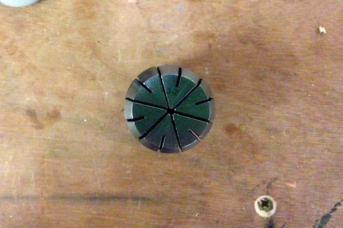
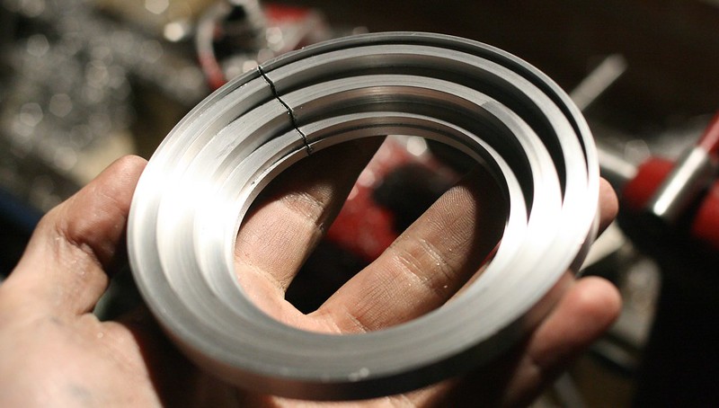
After the upper and lower plates were turned to round the large chunk of aluminium was turned mostly into chips - it will be a rudimentary pot chuck to facilitate facing the thin displacer cylinder plates and the smaller diameter flywheel later on. It still needs a bit of de-burring in this photo.
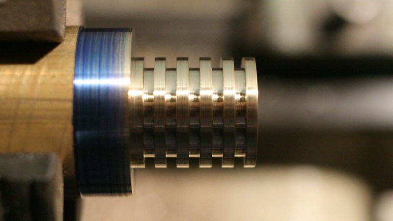
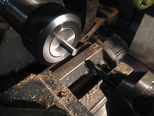
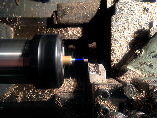
Boring this out took an incredibly amount of time - after the lathe motor stalled a few times I took a close look at it again: only 1/4 HP! It really struggles on even medium sized cuts near the OD.
That's pretty much what I have documented so far - I hope you've found it interesting. I've got an OU exam in a week's time so I should probably be concentrating more on that...
Aidan
I've started building a Ridders Coffee Cup Stirling engine here in Yorkshire, England.
After spending a year turning a lot of metal into swarf and not really getting anywhere other than fixing a few things on the lathe itself I decided a proper project would be a good start.
I appreciate these LTD stirlings are quite difficult to get running but hey, if you're going to do something why not jump in head first? There is also an almost worrying level of coffee consumption by everyone both at home and work, so what better to start with?
I only have a lathe, no mill, so I was looking in particular for something that could be achieved simply within these limitations.
First I downloaded the plans from ProjectsInMetal a few months ago and started to remake them in Autodesk Inventor. This is so I can learn the software and get my head around the parts before making chips.
The plans call for 5 mm thick end plates, but these are being made from 5mm sheets. They might be a little thinner than intended. I'm sure that'll be fine as long as the internal volume of the displacer cylinder doesn't change too much, and that's controlled by the cylinder walls, a separate part.
I don't have access to a bandsaw, so hacksaw it is all the way. I figured drilling around the edges would speed up the cutting process by removing most of the material for me. It did.
Once all the sections are cut out the jaggedy blank was super-glued to a large chunk of aluminium and very, very gently turned down to round with a bit of support from a live centre in the tail stock, a centre-drilled piece of scrap and an off-cut of some kind of anti slip matting from work.
Gently heating the metal sandwich on the gas hob and prying with the blade of a scalpel separated the two pieces nicely, with the sacrificial blank ready to use again for turning the upper plate.
I'll do this in the future with the window open from the get-go - it smells really bad.
After the upper and lower plates were turned to round the large chunk of aluminium was turned mostly into chips - it will be a rudimentary pot chuck to facilitate facing the thin displacer cylinder plates and the smaller diameter flywheel later on. It still needs a bit of de-burring in this photo.
Boring this out took an incredibly amount of time - after the lathe motor stalled a few times I took a close look at it again: only 1/4 HP! It really struggles on even medium sized cuts near the OD.
That's pretty much what I have documented so far - I hope you've found it interesting. I've got an OU exam in a week's time so I should probably be concentrating more on that...
Aidan