Request power feed wiring assistance.

Home Model Engine Machinist Forum

Help Support Home Model Engine Machinist Forum:

This site may earn a commission from merchant affiliate links, including eBay, Amazon, and others.

DickDastardly40

Well-Known Member
Joined
Oct 23, 2007
Messages
309
Reaction score
0
Fellas,

Looking for some help puzzling out how to wire up a common or garden windscreen wiper motor to make a controllable usable power feed for my milling machine.

I have:
a motor
a 13.8V 7A power supply
a home made means to drive the feed screw from the motor
a variety of toggle switches to isolate power and reverse direction
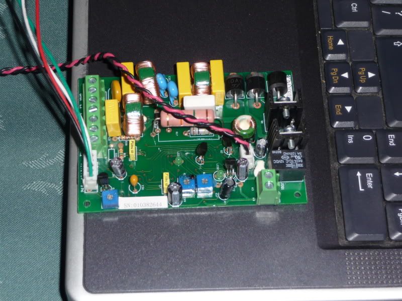
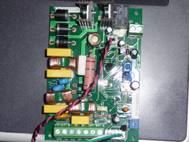
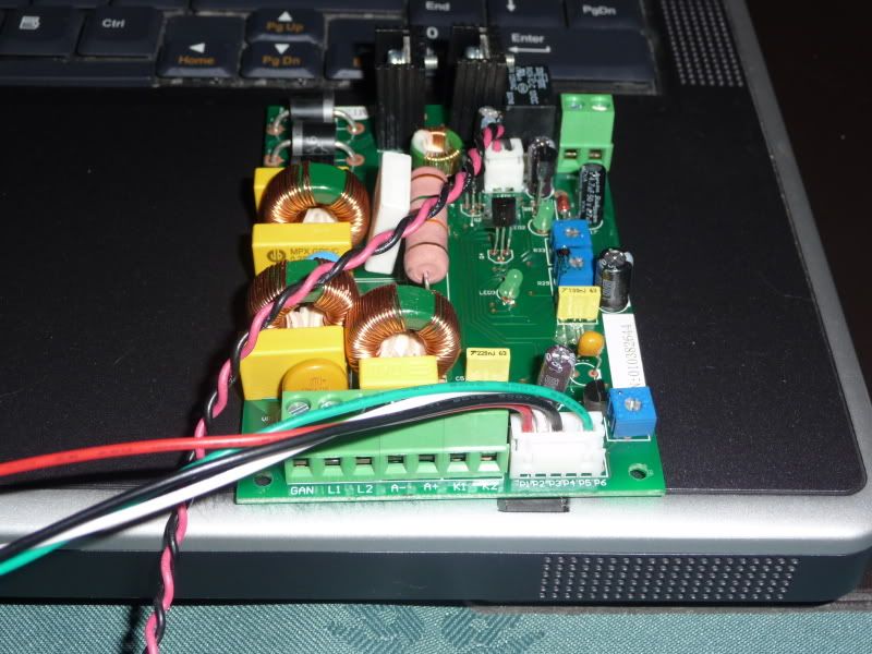
an X3 power feed control board (bought on a whim and possibly 240V)
An enclosure to put any circuitry into

I believe I the X3 feed control board needs a 5.7K potentiometer to go with it, but if it is for 240V then it's probably no good to me and I'll offer it for sale.

I would appreciate it if I could be led through whichever other purchases are required and how I solder them together. Links to components at maplin.co.uk would be especially helpful.

I did try using this for a giggle but as I knew it probably would worked OK for a minute then let its smoke out: http://www.maplin.co.uk/Module.aspx?ModuleNo=30310

A lot to ask I know, but grateful for any assistance.

Al
 
Hi Al

There's lots of circuits for DC Motor Speed Controllers on the net. Depends how savvy you are at building them.
I have some myself, if I can put my paws on them. Most are PWM, ( one is variable DC. OK for 12V. 5A, uses a L200 regulator i.c. if you know it.) Needs a fan, being linear.
If you download the .pdf for L200, its the same as a 'boosted' variable PSU. I put two series pass transistors in it.
Are you sure that's a 5.7k Pot. on the X3 ?? Not a standard value, 4.7k is.
Not sure how much of this makes sense to you. If you don't do too much 'lectronics, it won't be any good.
e-mail me if you want, see what I can do to help.

Dave


Dave,

Thanks here are some pics of the board I have.

P1000673.jpg

P1000672.jpg

P1000671.jpg


The gent I bought it from said 5.7K, I'm afraid I know no better. I can solder but am not 'lectroncally savvy, 440V 3 phase being more my thang.

Any further pointers gladly pounced on.
 
Hi Al

Yup! Nice. I recognise the components, I wonder what they're doing??

Pics. don't help much, I'm afraid. It's difficult to work out the function of the circuit without a schematic.

I design and build my own speed controllers when I want one. Easier than trying to adapt some existing kit usually.

A part number of the devices on the heatsinks may give a clue. These are the black metal things sticking up next to the black box with 12V 3A 125VAC etc. on it. It looks like a relay.

When you get things like that, often they decline to function because they need other control voltages, contact closures, or the like on the connection blocks. Unless the schematic is available you are there for the duration.

But if you have a 13V DC PSU. you are 2/3 's of the way there anyway. The speeed controllers are fairly easy to make. Must be. I can do 'em .. ;D

Not too helpful am I. Sorry :-[


Dave
 
Judging by the fact that ALL of the components are passive except the two on the heatsinks...This is a PWM circuit. The passive components(inductors and capacitors) being used for timing purposes for the active components. The connectors show some signal names..the L1 and L2 are probably AC voltage inputs the A+ and A- are probably the DC output and the K1 and K2 are most likely for driving relays off board.(probably for motor reversal)

Without more info that's as far as I'm willing to guess. If you have a multimeter you could try hooking it up and seeing what voltages are where??? If you blow it then its as useful to you as it is right now without being hooked up. No?


Kermit
 
DC motor drives can vary wildly in complexity and performance. If you connect you power supply directly to your motor, you will have one speed that will drop off with increasing load. If it is an unregulated supply, you could plug it into a conventional light dimmer and have variable output voltage. If it is a regulated supply, then you need a motor control following it. Complexity is dependent on the features you want. A good motor control will have min and max speed settings, current limiting and use some kind of feedback to get constant speed with varying load.

Your board looks like it has two power SCRs (stud mounted to heat sinks) in the corner. If so, then it is a phase angle drive which is less desirable (but quite usable) than a PWM drive which would have an integrated circuit driving MOS FET transistor outputs.

I can't offer you much help, just trying to explain where you are at.
 
Stans information sounds right and further inspection shows 4 signal transistors for a total of 6 actives in the circuit.

Still....


Sorry couldn't offer more help,
Kermit
 
Back
Top