moya034
AbsentMindedMetalWorker
- Joined
- May 23, 2013
- Messages
- 72
- Reaction score
- 20
(note: This content has been posted by me elsewhere on the internet, and has largely been "recycled" for posting here. That being said, I think the membership here will be intersted in this project. I've edited the content as it's all in the past tense now, so please forgive me if I missed something that makes it seem in the present tense.)
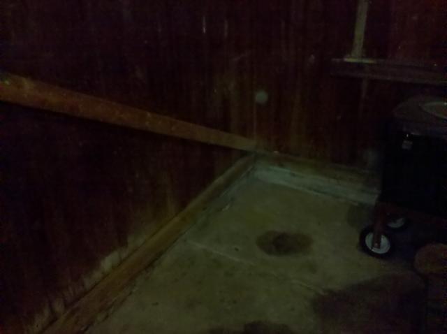
Ever since I was a little kid, I have always longed for a metal lathe (I'm 31 now... it took me a few years") ). Back in Februrary of 2010 I purchased this off of Craigslist:
). Back in Februrary of 2010 I purchased this off of Craigslist:
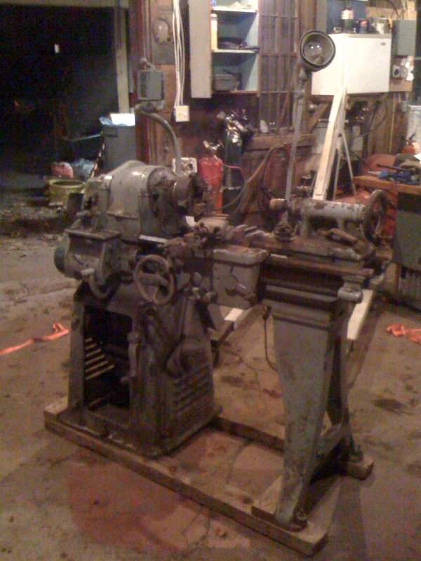
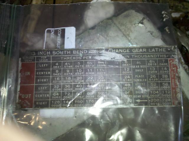
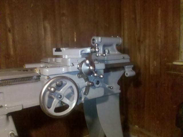
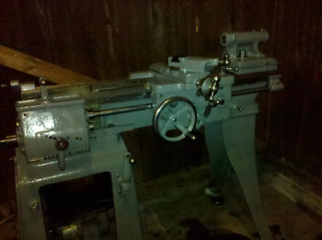
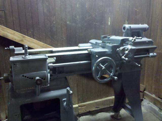
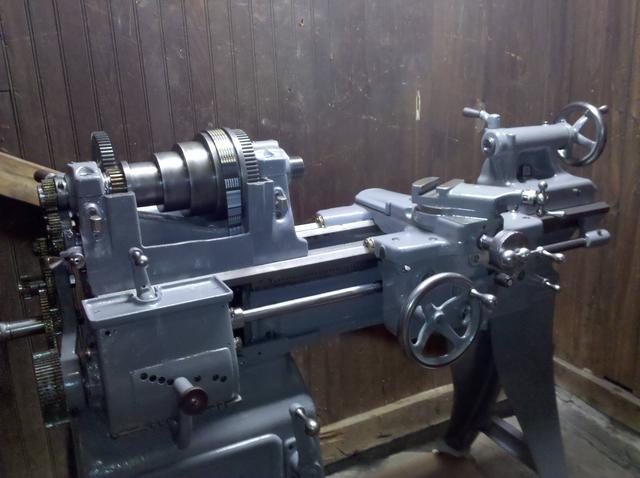
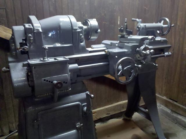
It's a 13" South Bend lathe of 1945 vintage. It's a short bed measuring in at 4 feet effectively giving 16" between centers. It's shipping weight is listed as 1460 lbs including the crate. Steve Wells has a 1948 SB catalog posted if you are intersted. My lathe is on page 23. These short bed lathes were popular in schools. I haven't ordered the serial number card from SB yet, but I do know the gentleman I got this from purchased it from the Danbury Mint.
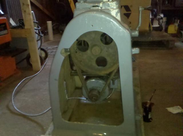
After bringing the machine home, I removed the 1 HP three phase motor and stuck on a very old 1/2 HP single phase motor that was lying around to play with it. Long story short it didn't work well. The bearings were shot, and the only way to start the machine was to wrap a strap around the pulley cone and do a pull start.
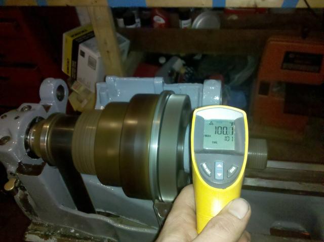
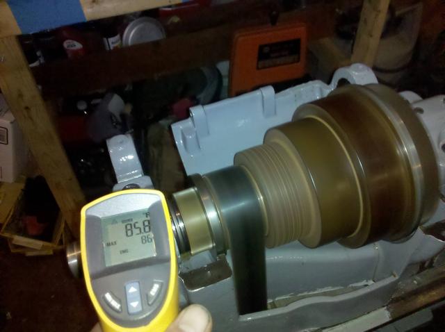
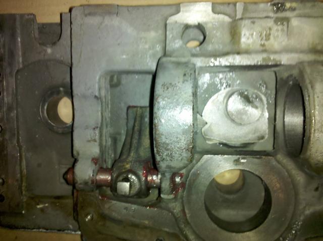
I did not run the spindle for too long. Inspection with an infared thermoter revealed the left bearing was starting to overheat. I measured the bearing clearances. The left came in at 0.0015" and the right at 0.0035". South Bend specifications is between 0.001" - 0.002". Since the left bearing is within spec, I assumed that it was having a lubrication problem. As far as the right bearing goes, removing one of the 0.002" shims should bring it into spec.
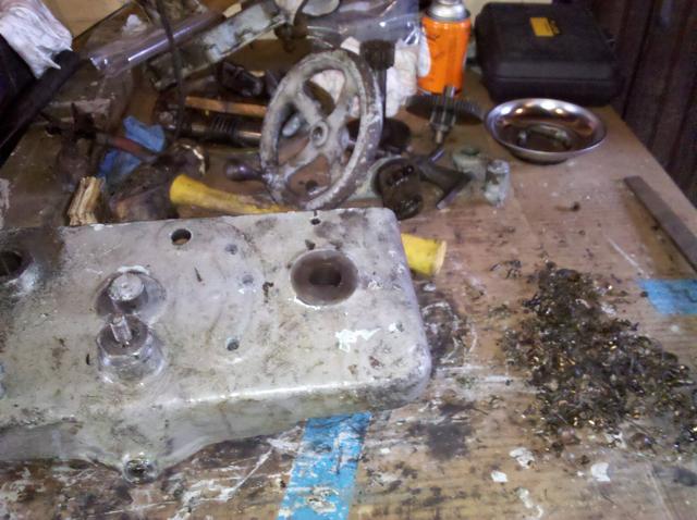
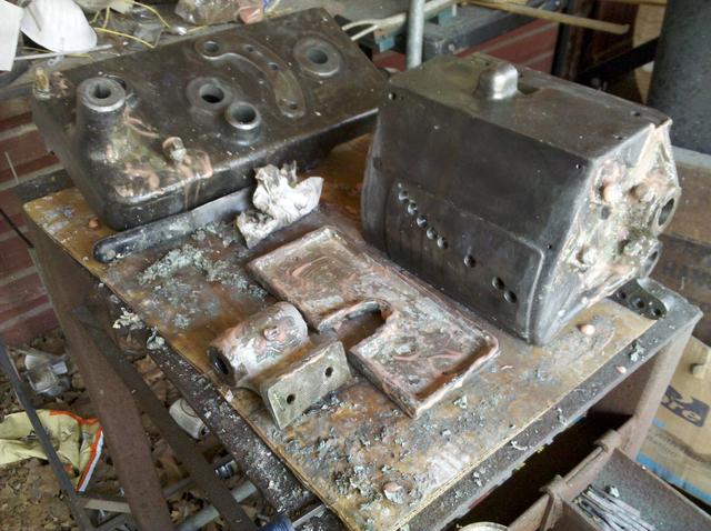
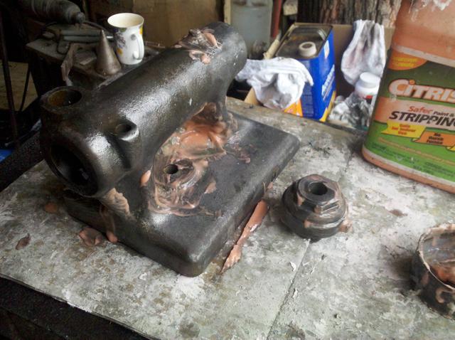
At this point, I realized that complete disassembly of this lathe had to happen. It was quite dirty, had a bit of rust (no bad corrosion, however), clogged lubrication felts, chips in every crevice imaginable, old lubrication packed with dirt, and an absolutely horrible paint job. It turned out this lathe had 3-7 layers of paint, depending on how easy the part was to remove from the machine. The color was putrid and paint was in places it didn't belong.
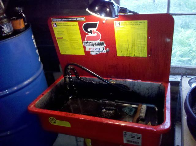
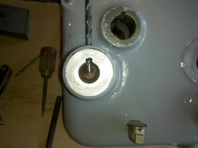
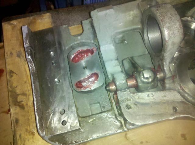
After removing the spindle and bearings from the headstock it was evident there was a lubrication issue due to clogged felts. I'm convinced any old SB lathe needs it's spindle pulled to check the felts. The left bearing that had been heating up was covered in varnish, but only had very very light scoring and was completely servicable without any honing. Soaking the bearing in solvent (I forget what I used) removed the varnish relatively easily.
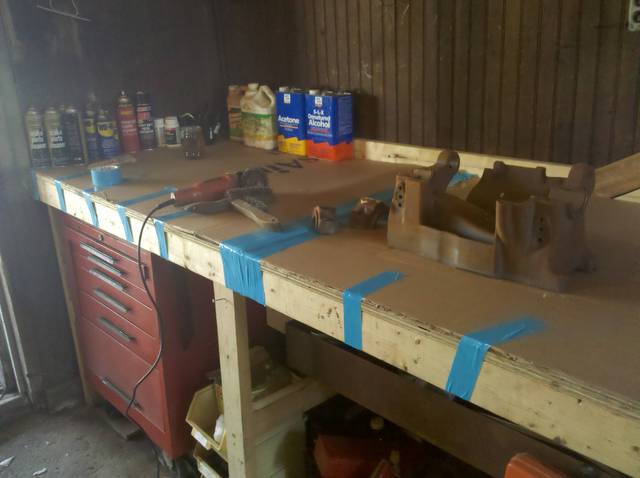
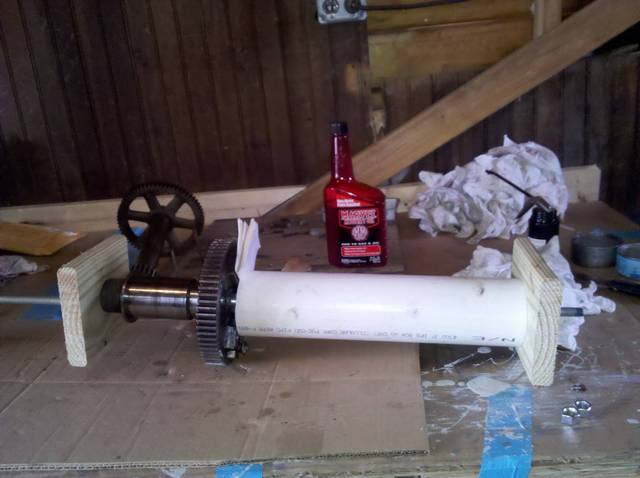
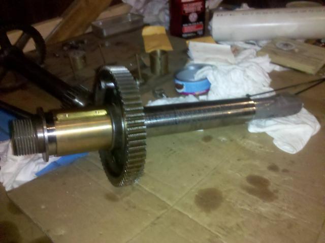
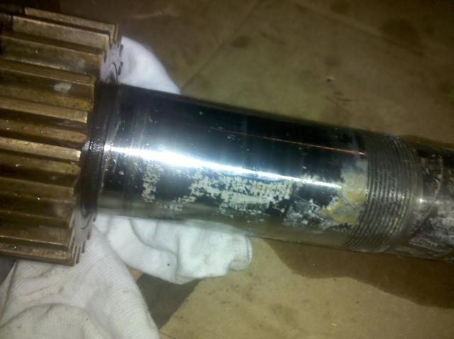
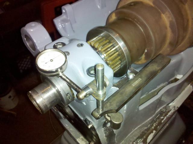
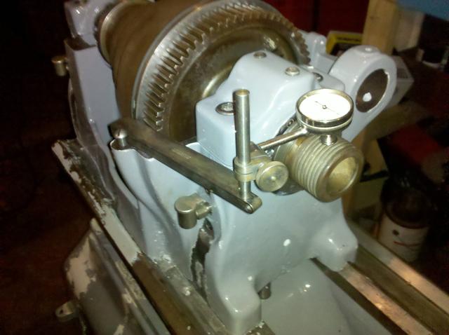
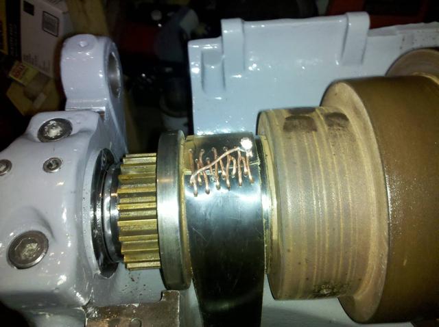
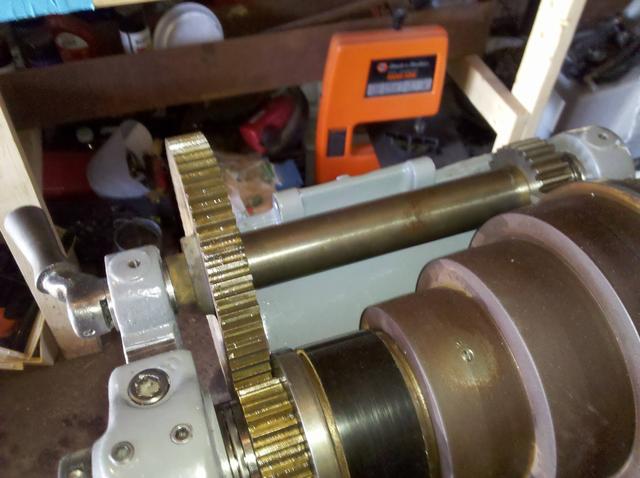
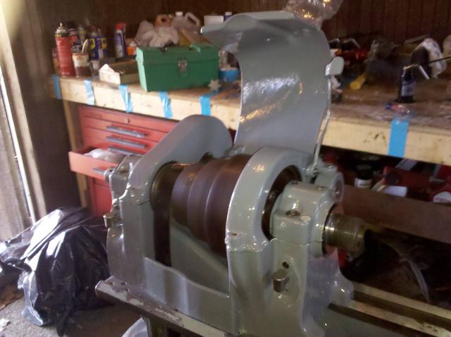
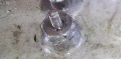
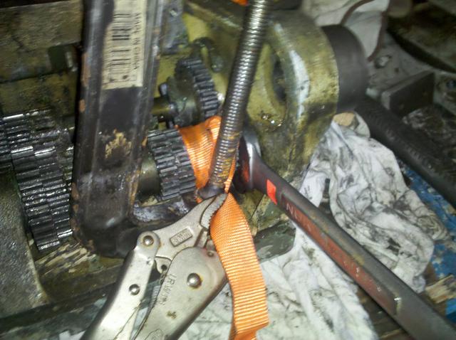
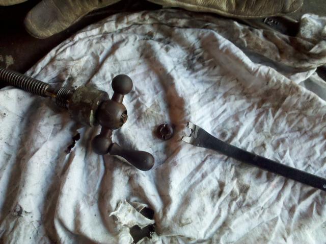
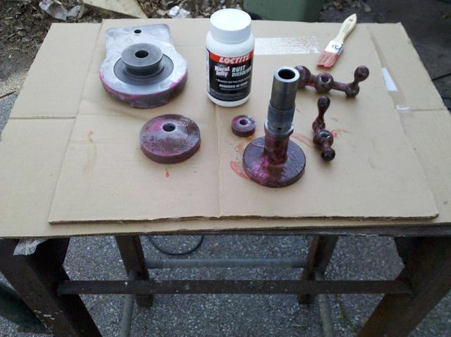
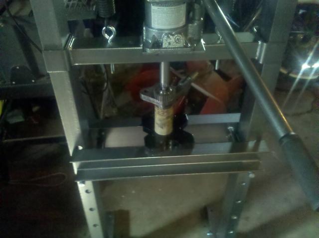
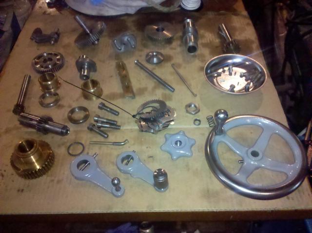
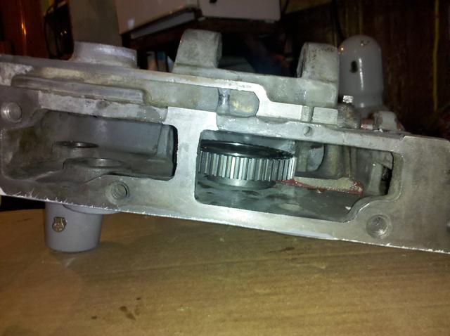
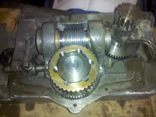
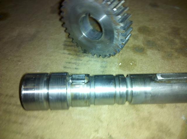
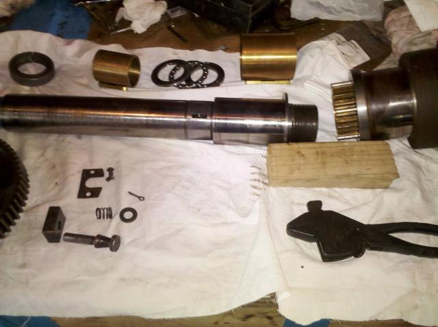
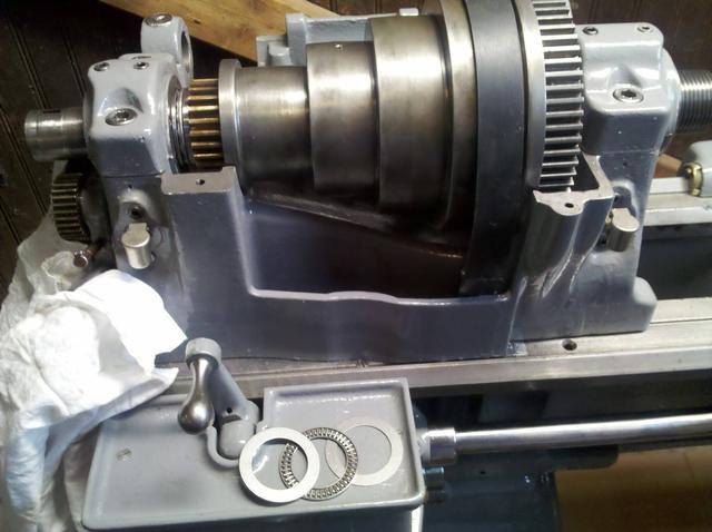
I also found out that my lathe had an incorrect bull gear on it. The 13" had two spindle sizes, mine has the smaller one. Someone had fit a bull gear for the larger spindle on this one with a brass bushing to take up the space. I wasn't crazy about this and found the correct bull gear on ebay. In the image here I was testing it to make sure it was the correct fit, which it was. Not the tape to protect the small bearing journal and take up nut threads while removing the pulley cone and bull gear.

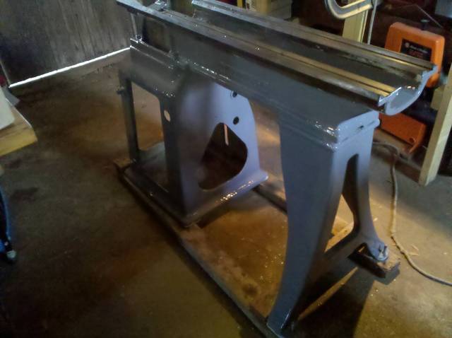
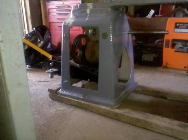
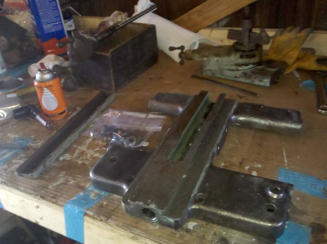
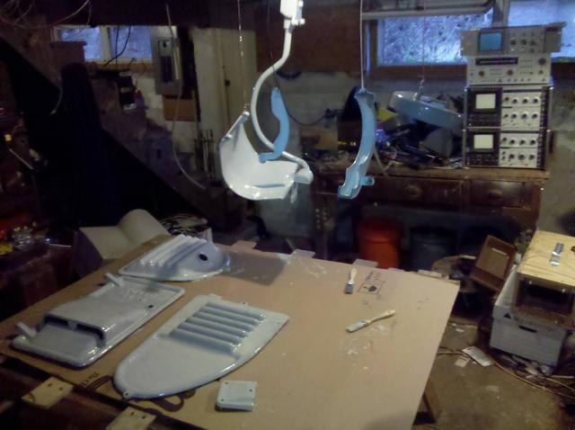
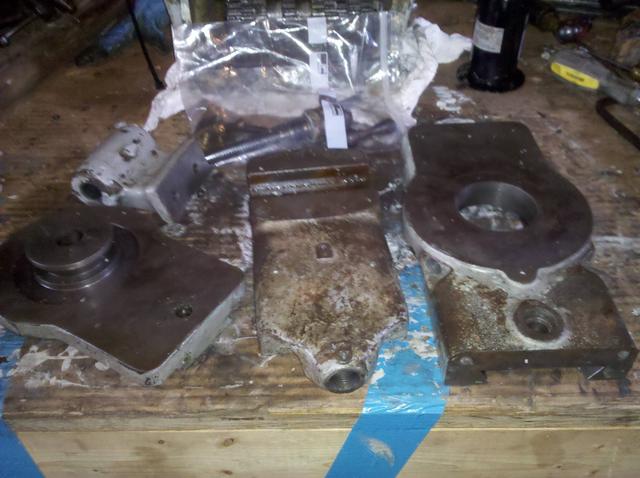
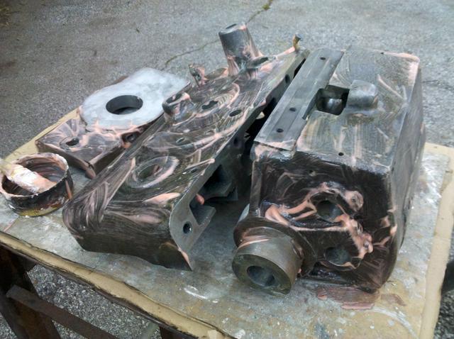
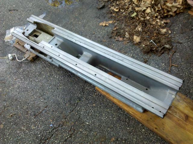
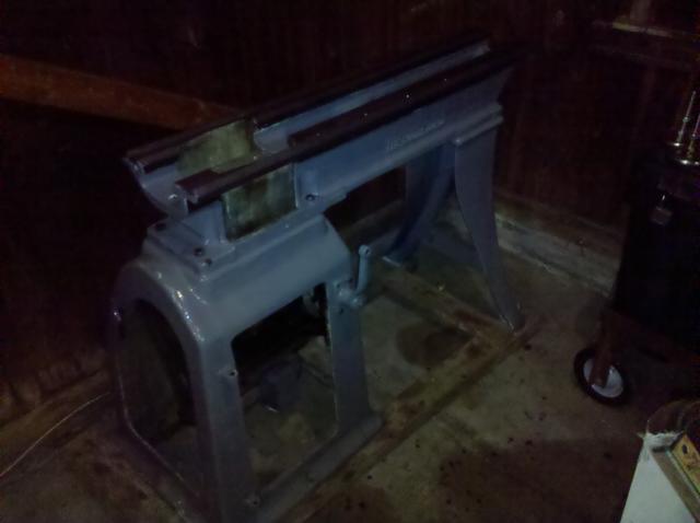
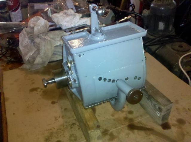
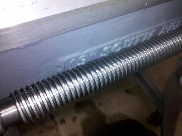
After spindle and headstock disassembly I removed the carriage, gearbox, lead screw, and unbolted the lathe bed from the pedestal and legs. This was the point where the painting phase started. For paint, I chose the Tractor Supply enamal tractor paint. For paint stripping on the lathe bed, pedestal, and leg I used a heat gun with putty knife to get off as much as possible, then gave it several coats of Citristip. Citristip is not the most effective paint stripper out there, but it is without a doubt the most freindly one to the environment and humans.
Once I had bare metal, they got a good bath of acetone. We all hear that you need to use acetone with good ventilation. Let me tell you, that is not a lie. When doing the pedestal I got an acetone headache. Lesson learned!


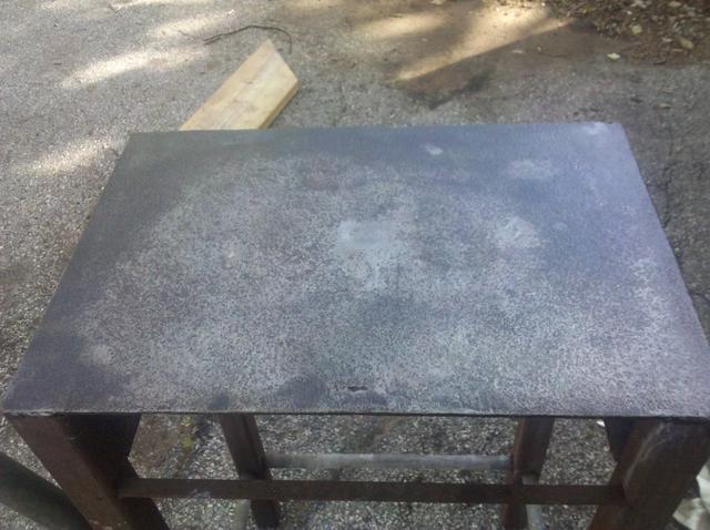
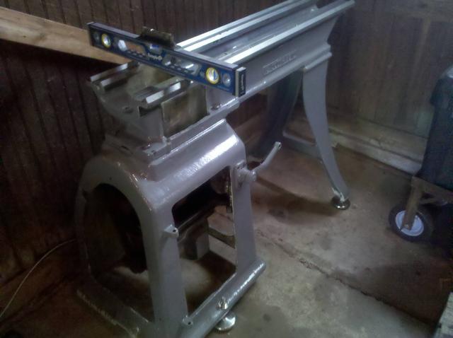
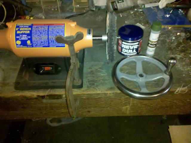
I have a magic table... you can adjust it's height with a crank handle! This made putting the lathe bed back on the pedestal and legs an easy one man job.


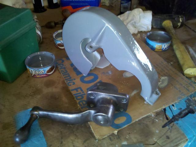
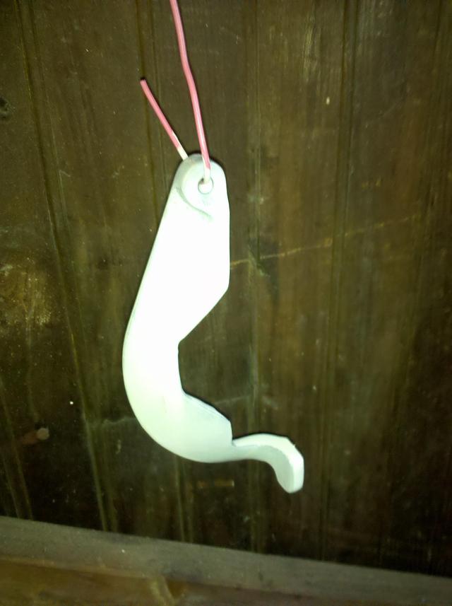
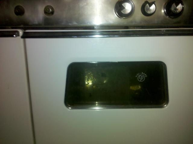
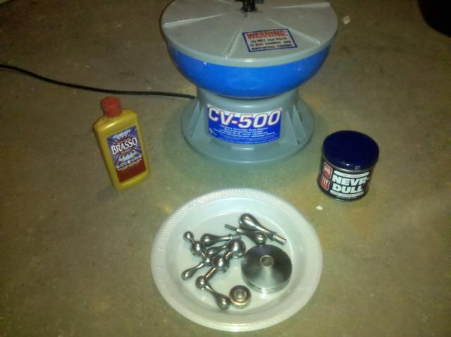
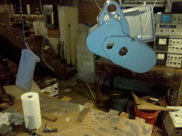
I had preformed an electrolysis experiment on the bull gear gaurd to remove the paint. It worked depsite my terribly primitive setup.


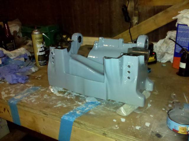
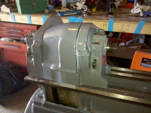
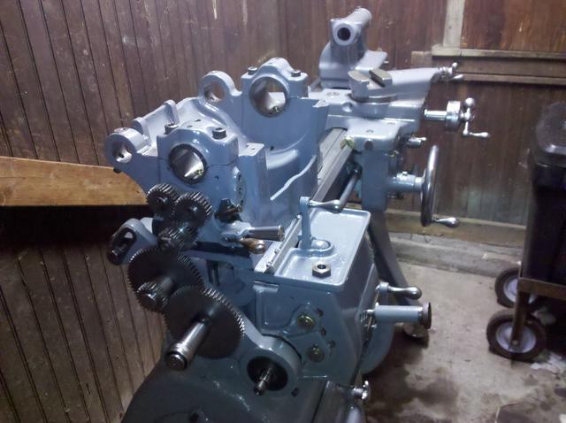
At that point, the next step was to work on the headstock. I had it and the bearing caps blasted by a local poweder coating company. Never did get around to painting it tho. At this point, various life events took me away from the project.
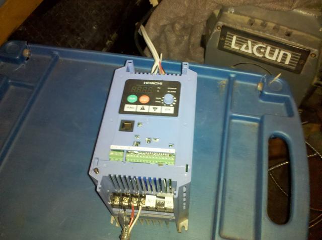
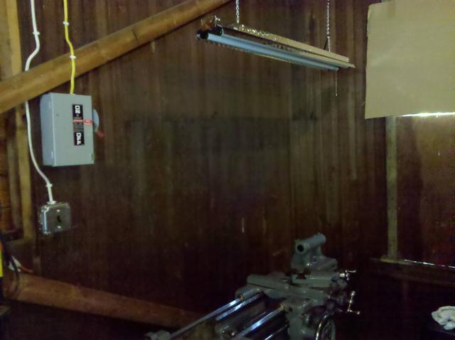
In December of 2010 I purchased a Hitach X200 VFD to run the 3 phase motor.

I still never got back to painting that darn headstock...
Those are all the old surving pics. There were more taken but I had a hard drive failure, and the internet only kept a few of them around.
Ever since I was a little kid, I have always longed for a metal lathe (I'm 31 now... it took me a few years
). Back in Februrary of 2010 I purchased this off of Craigslist:
It's a 13" South Bend lathe of 1945 vintage. It's a short bed measuring in at 4 feet effectively giving 16" between centers. It's shipping weight is listed as 1460 lbs including the crate. Steve Wells has a 1948 SB catalog posted if you are intersted. My lathe is on page 23. These short bed lathes were popular in schools. I haven't ordered the serial number card from SB yet, but I do know the gentleman I got this from purchased it from the Danbury Mint.
After bringing the machine home, I removed the 1 HP three phase motor and stuck on a very old 1/2 HP single phase motor that was lying around to play with it. Long story short it didn't work well. The bearings were shot, and the only way to start the machine was to wrap a strap around the pulley cone and do a pull start.
I did not run the spindle for too long. Inspection with an infared thermoter revealed the left bearing was starting to overheat. I measured the bearing clearances. The left came in at 0.0015" and the right at 0.0035". South Bend specifications is between 0.001" - 0.002". Since the left bearing is within spec, I assumed that it was having a lubrication problem. As far as the right bearing goes, removing one of the 0.002" shims should bring it into spec.
At this point, I realized that complete disassembly of this lathe had to happen. It was quite dirty, had a bit of rust (no bad corrosion, however), clogged lubrication felts, chips in every crevice imaginable, old lubrication packed with dirt, and an absolutely horrible paint job. It turned out this lathe had 3-7 layers of paint, depending on how easy the part was to remove from the machine. The color was putrid and paint was in places it didn't belong.
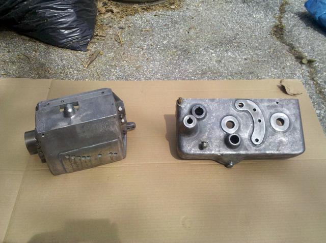
After removing the spindle and bearings from the headstock it was evident there was a lubrication issue due to clogged felts. I'm convinced any old SB lathe needs it's spindle pulled to check the felts. The left bearing that had been heating up was covered in varnish, but only had very very light scoring and was completely servicable without any honing. Soaking the bearing in solvent (I forget what I used) removed the varnish relatively easily.
I also found out that my lathe had an incorrect bull gear on it. The 13" had two spindle sizes, mine has the smaller one. Someone had fit a bull gear for the larger spindle on this one with a brass bushing to take up the space. I wasn't crazy about this and found the correct bull gear on ebay. In the image here I was testing it to make sure it was the correct fit, which it was. Not the tape to protect the small bearing journal and take up nut threads while removing the pulley cone and bull gear.
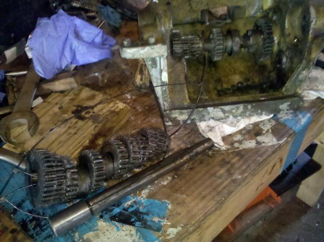
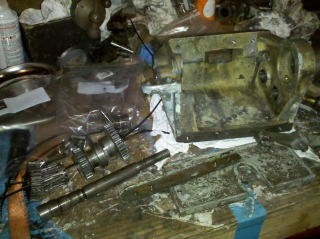
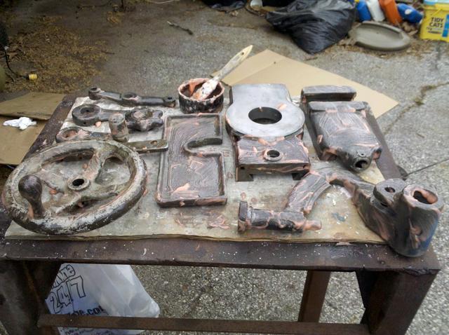
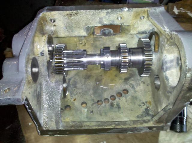
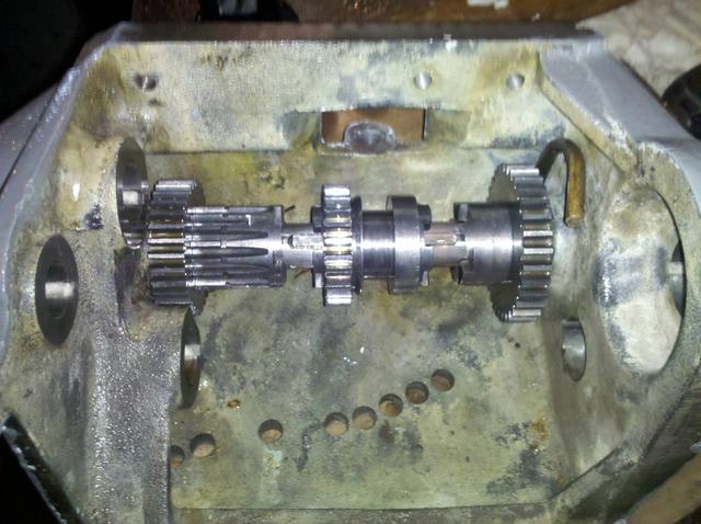
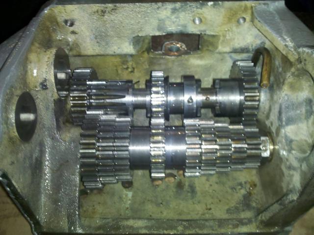
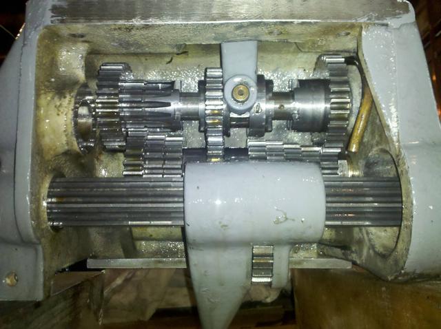
After spindle and headstock disassembly I removed the carriage, gearbox, lead screw, and unbolted the lathe bed from the pedestal and legs. This was the point where the painting phase started. For paint, I chose the Tractor Supply enamal tractor paint. For paint stripping on the lathe bed, pedestal, and leg I used a heat gun with putty knife to get off as much as possible, then gave it several coats of Citristip. Citristip is not the most effective paint stripper out there, but it is without a doubt the most freindly one to the environment and humans.
Once I had bare metal, they got a good bath of acetone. We all hear that you need to use acetone with good ventilation. Let me tell you, that is not a lie. When doing the pedestal I got an acetone headache. Lesson learned!
I have a magic table... you can adjust it's height with a crank handle! This made putting the lathe bed back on the pedestal and legs an easy one man job.
I had preformed an electrolysis experiment on the bull gear gaurd to remove the paint. It worked depsite my terribly primitive setup.
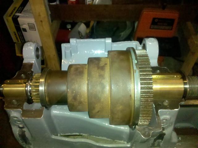
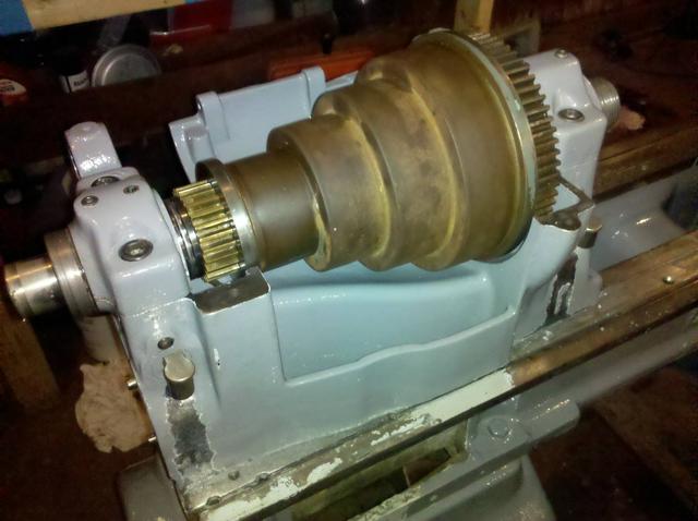
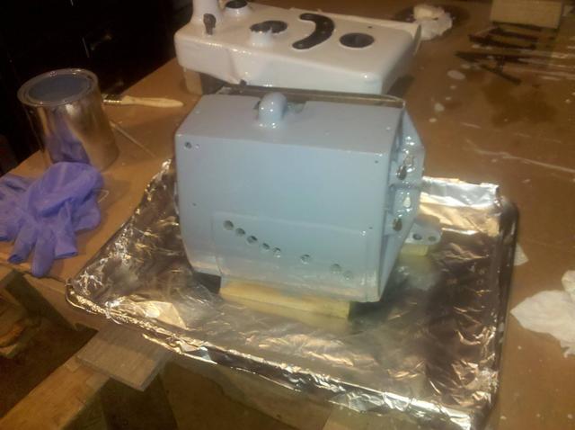
At that point, the next step was to work on the headstock. I had it and the bearing caps blasted by a local poweder coating company. Never did get around to painting it tho. At this point, various life events took me away from the project.
In December of 2010 I purchased a Hitach X200 VFD to run the 3 phase motor.
I still never got back to painting that darn headstock...
Those are all the old surving pics. There were more taken but I had a hard drive failure, and the internet only kept a few of them around.