Remeber your first engine build--- Boll Aero----

Home Model Engine Machinist Forum

Help Support Home Model Engine Machinist Forum:

This site may earn a commission from merchant affiliate links, including eBay, Amazon, and others.

burkLane

Active Member
Joined
Dec 31, 2015
Messages
33
Reaction score
24
Inspired by the many threads on these forums I have also decided to take on the challenge of building a working device from some bits of material. This will be my first engine build and the focus for me will be on not only making the engine but also to use, refine and learn cnc programing and cam setups by using cnc code and tools for every possible operation.
Wanting to also learn all the tricks by asking questions from the many masters around here that build such amazing projects and take the time to share.
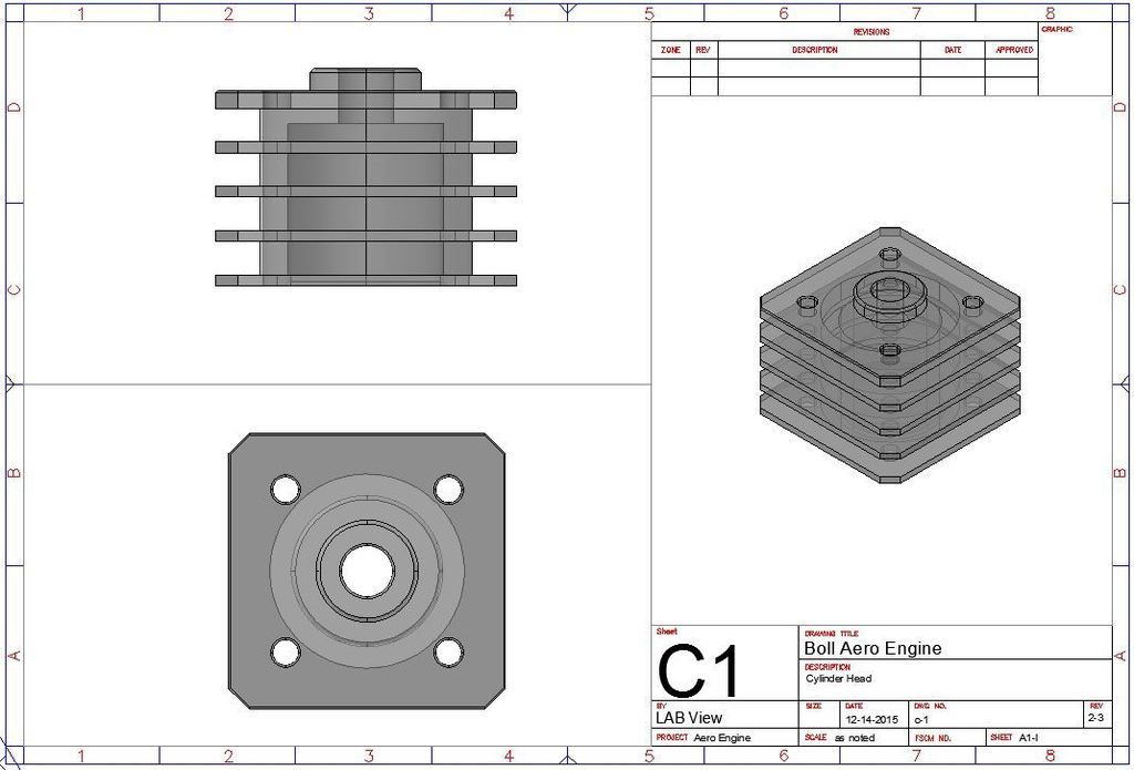
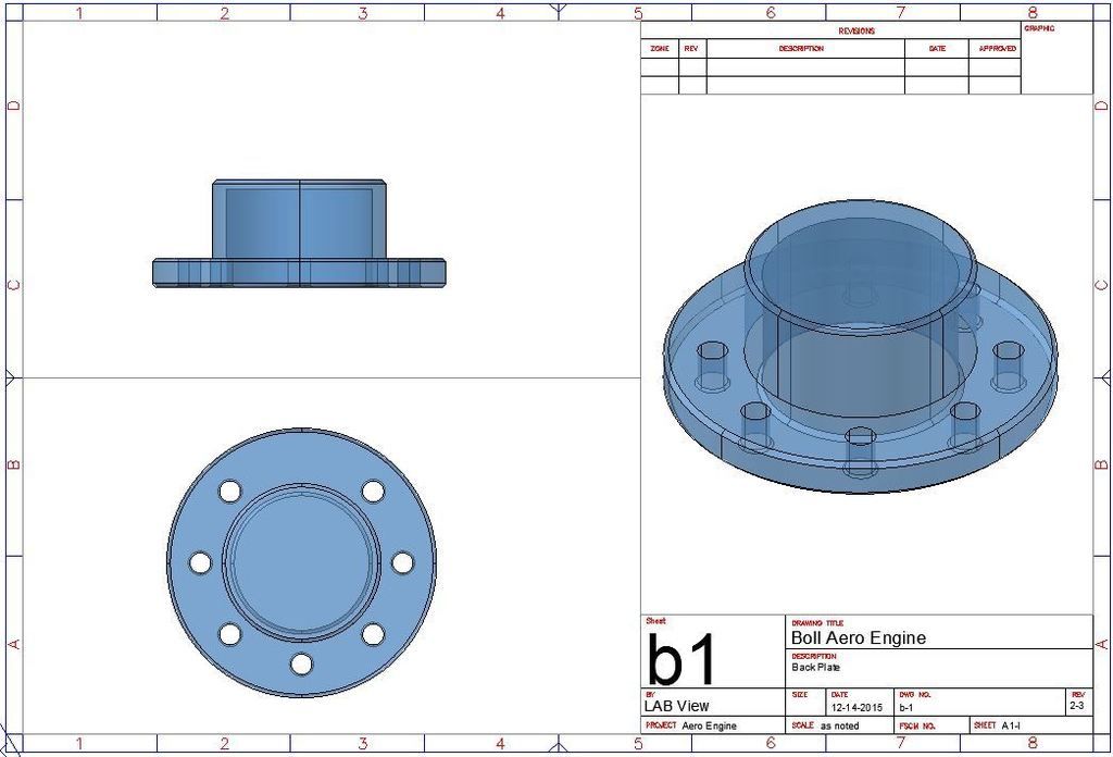
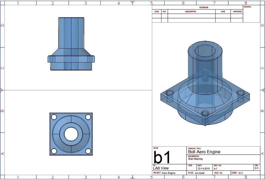
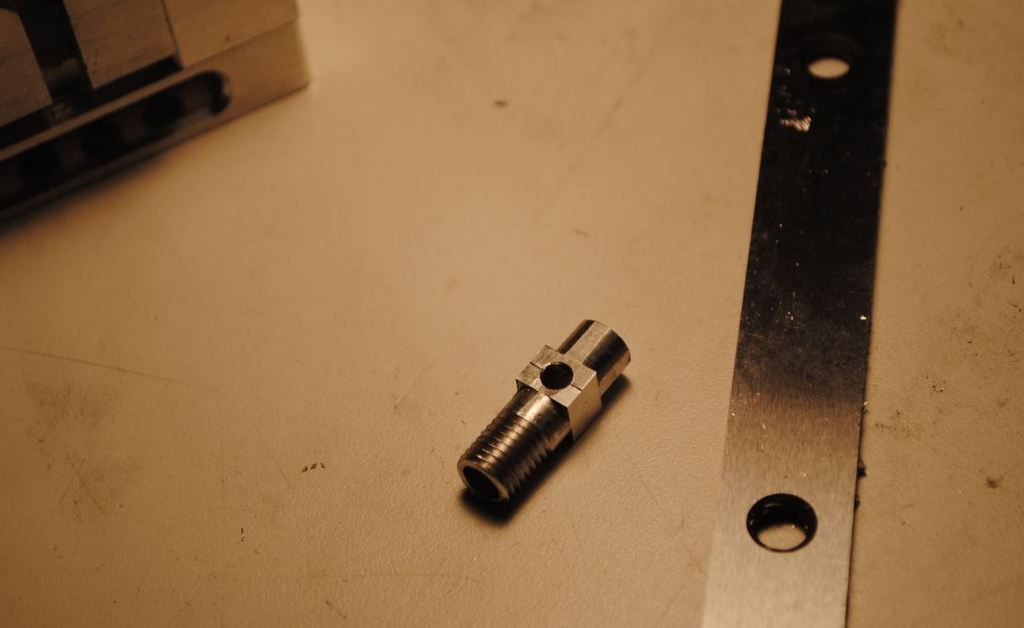
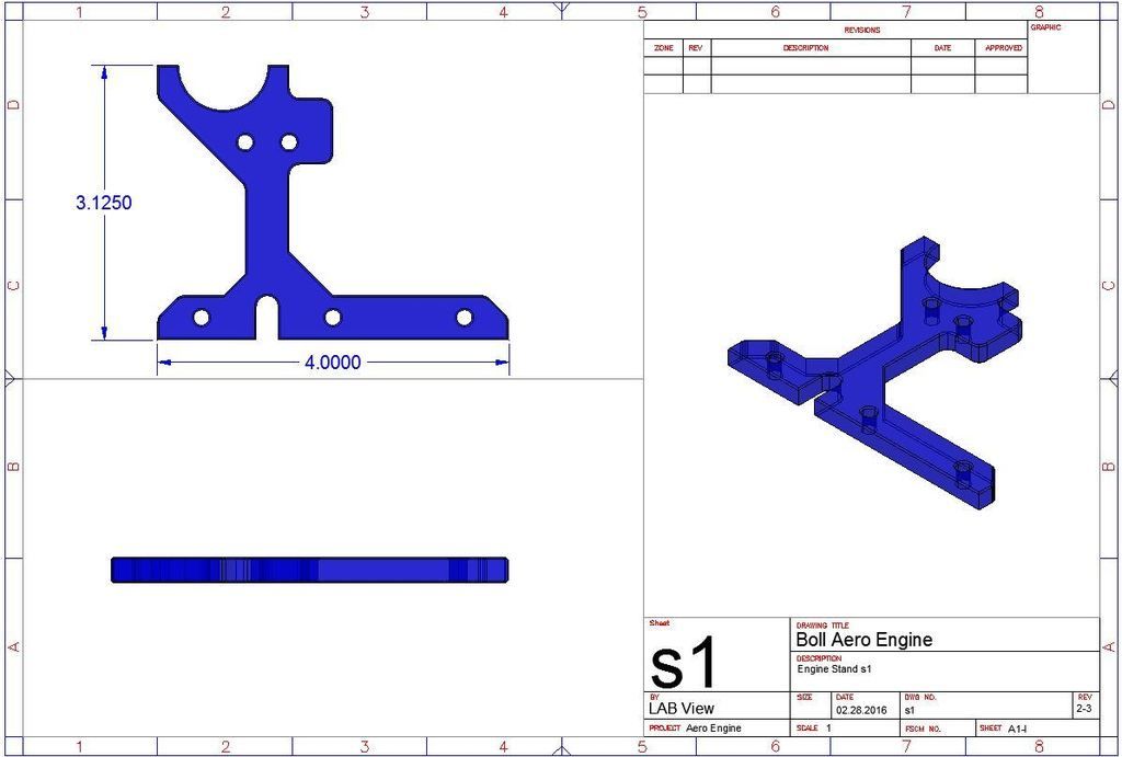
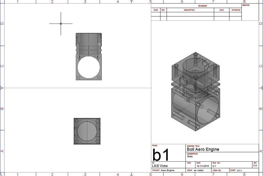
First like many around here get in the cad system and model up some parts.

Crankcase drawing

CrankcaseCaD_zpsxkv3mdbc.jpg


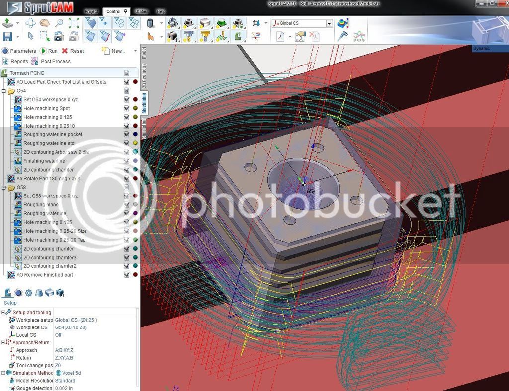
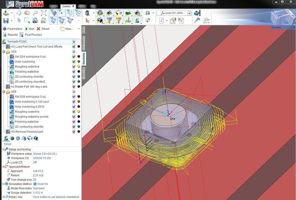
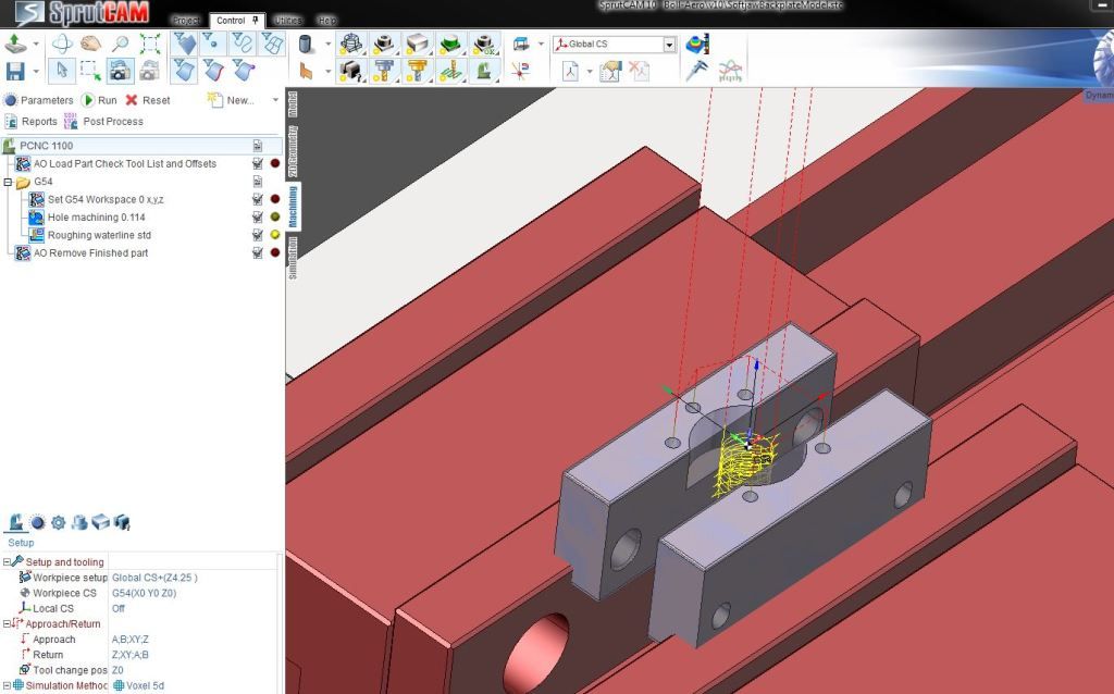
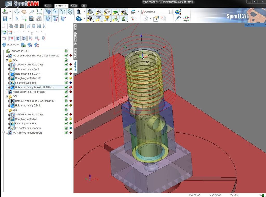
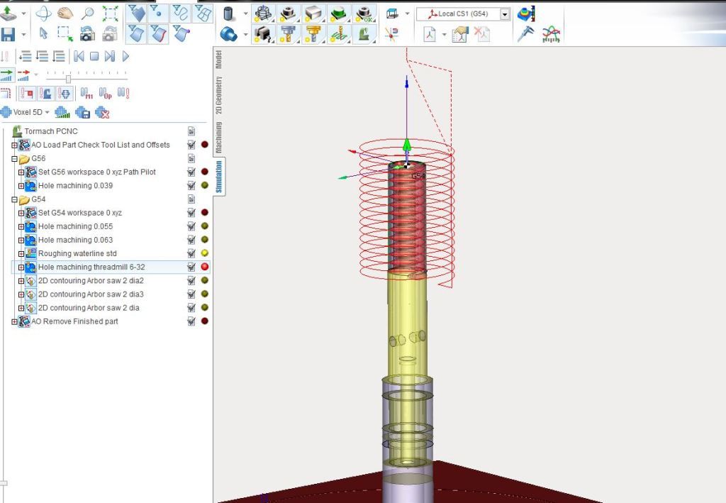
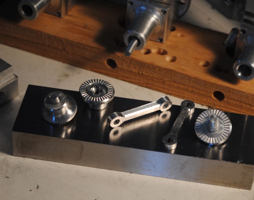
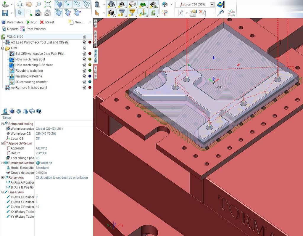
Then import and setup cam operations
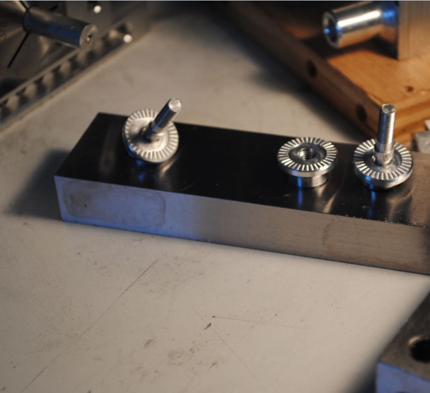
I Tend to spend a great deal of time doing this to avoid broken tools and spoiled parts. Setting up every operation to mill each feature on each side complete so when done I remove a finished part.

CrankcaseCam_zpsu9myibcq.jpg


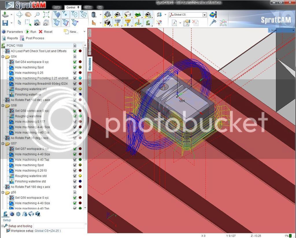
Not always easy to do and very frustrating at times. After a while many of these functions become easy to setup and results are great most of the time.


Crankcasepart_zpskokyrcoj.jpg


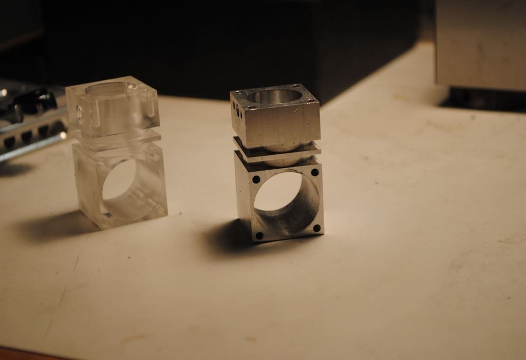
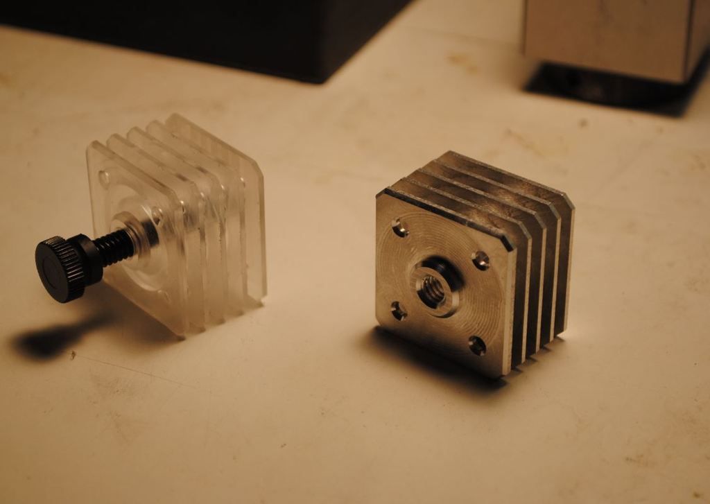
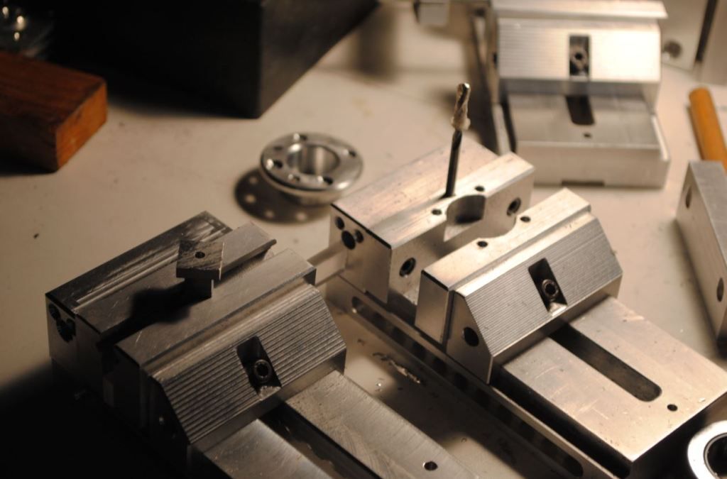
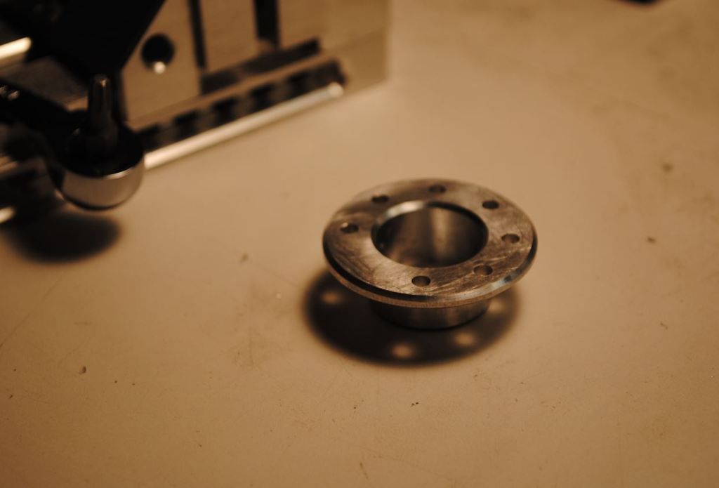
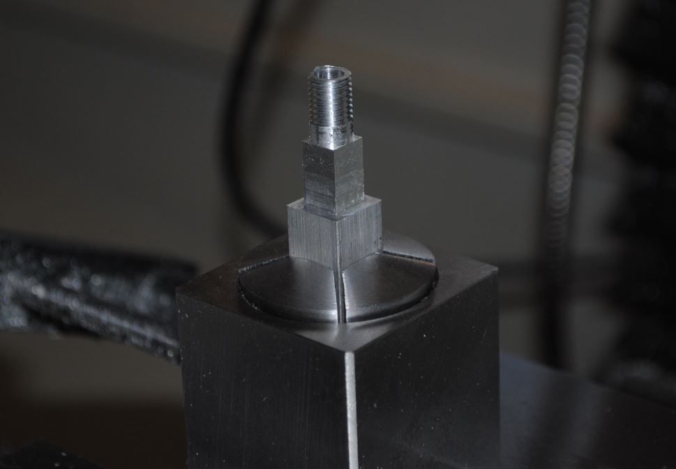
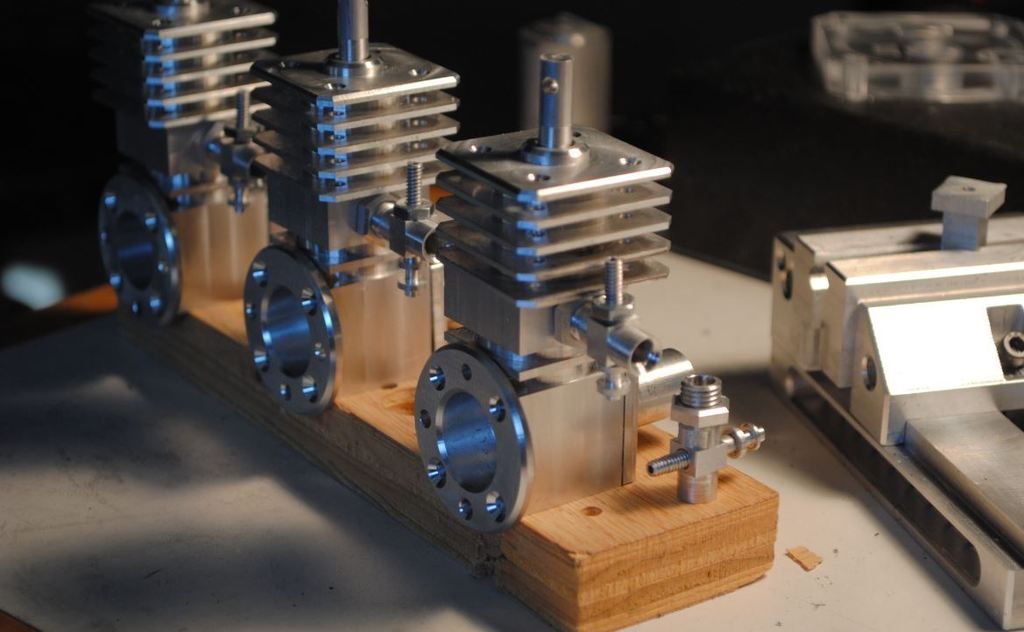
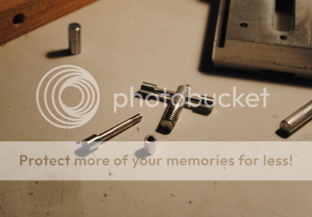
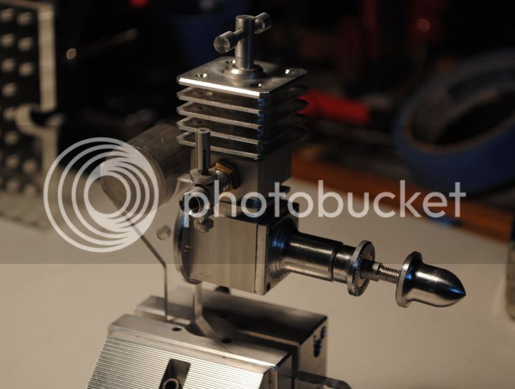
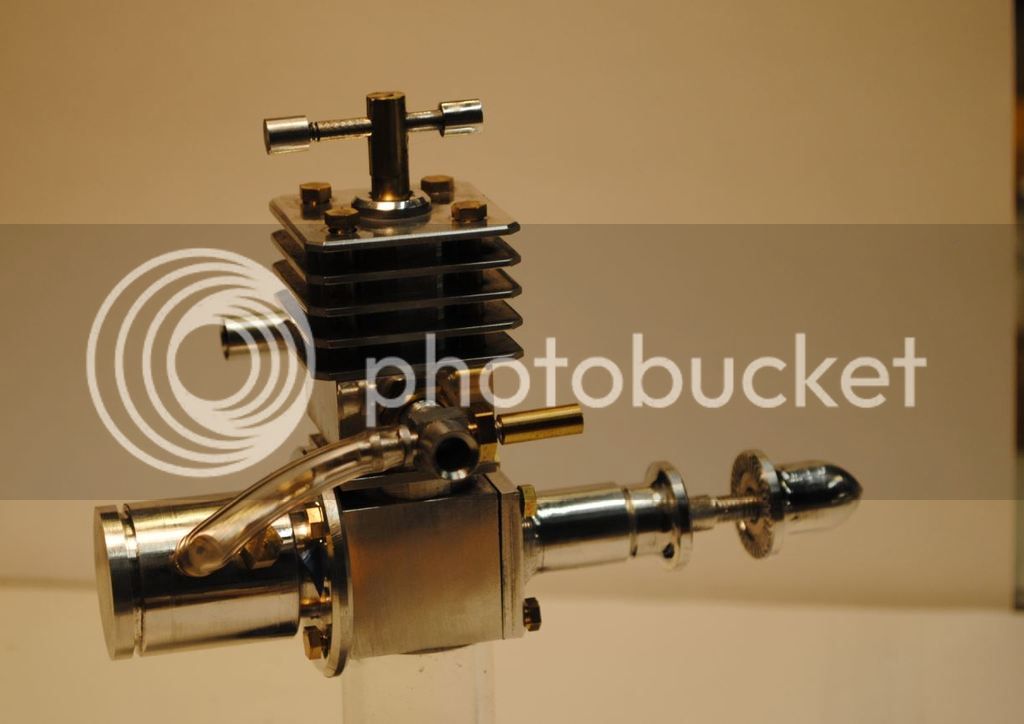
I didn't have material for the first couple parts so I made some prototypes out of acrylic shown above. Easy to test new version of cam bloat ware and shake out some operations using this very forgiving material.

Decent start to project and first engine build thread. :)
Thanks for reading and following along.
Lane
 
I've used acrylic in the past also. It's good stuff as long as you don't get it hot.
 
I envy you guys with the CAD/CAM know how; it's so cool! I'll be watching
this build also!

Pete

Thanks!
I envy you guys with all the machine know how! Decent drawing skills is about all I can bring to table at this point.

I've used acrylic in the past also. It's good stuff as long as you don't get it hot.


Little fragile to hold and machine. I have a fair amount of it laying around shop so its fun to use in projects or machine prototypes out of.
 
Will be following your postings. Mine was half done 10 years ago. Did not then have the machining skills and the honing/lappping skills.
Piston and sleeve must be lapped to give high compression.
 
Next part was cylinder head. While drawing this I decided to change the style a little just to be different. Like the crank case above I added a fin and changed spacing a little.

CylinderheadCaD_zpsfpvyq6ca.jpg


Then imported into cam and worked on setup of operations and tools.


CylinderheadCam_zpsn7hjtiei.jpg


Off to the shop to size up some material and mill out some parts


CylinderheadPart_zpsa94qatg5.jpg


Pretty fun parts to make. Using an arbor saw is slow milling. I tried to use the time cleaning up shop and putting tools away.
 
Next part I completed was the back plate. Using the same methods as before first model the part.

BackPlateCaD_zps9stpqj7s.jpg


Then import model into cam software and setup fixtures and operations.


BackPlateCam_zpsiddrdtyo.jpg


Didn't think this part was to difficult until a made one and noticed I missed some design features "counter sinks" on one side. this made it more difficult to pick up those features on another side with accuracy. Only way I could think of to do this on existing part or new ones was to make a custom soft jaw fixture to hold, index and locate the part. Back to drawing board!
Designed up and setup cam to mill some soft jaws.

SoftJawBackPlateCam_zpsvxi0xesl.jpg


Milled up a couple jaws and mounted them for use.

SoftJaws_zps4nnndgh6.jpg


First back plate with no counter sink features ready to position in soft-jaws for added operation. Will use these for making a couple more :) complete with counter sinks after I revise the model.

BackPlatePart_zpssezhctld.jpg


Now on to next part .
Enjoy the day!
 
Stepping thru the design model each part as before.
Main bearing was next
MainbearingCaD_zps2b0mbghu.jpg


Finished model is then setup in cam like before and then parts are made.

MainbearingPart_zps1ai93lmn.jpg


Repeating these steps for each part
is straight forward. The next few parts were getting much smaller and wanting to mill every single feature was a challenge to work out. I setup single point threads both internal and external on next few parts much like shown below.

VenturiCam_zpszva9iwoy.jpg


Wish I could say this was easy. I found little in my cam setups that I could calculate on first try, my understanding of thread forms and published values did not yield correct results for finished diameter. In time I could zero in on good values for each setup but still have no quick way to do this.

Threadmill1_zpsbmezdtwm.jpg


End up with decent part, this one was crimped in vise :(

VenturiPart_zpswi5b41wx.jpg


Next part was the spray bar. It took a number of different cam operations and reordering to get even close part to a part. The 6-32 o.d. threads with hole down center left very little material to work with. and the 6-32 thread mill operation took about 3 tries to get right settings. :(

SprayBarCam_zpsgf7u9dxz.jpg


Number of failures, oh well part of learning. But did end up with some usable prototypes.

SprayBarPart_zpslb38myow.jpg


And a current picture of progress at this point

1st rule of government contracting why build one when you can have 3 at 3 times the cost. :) more like good, better, best!

Assembly4Pic_zpsznvtsfwm.jpg


Hope you enjoyed the pictures and brief write ups so far!
 
Will be following your postings. Mine was half done 10 years ago. Did not then have the machining skills and the honing/lappping skills.
Piston and sleeve must be lapped to give high compression.


I will complete the design :) who knows if I will get one to run. I have very limited machining skills and looking to do projects like these to learn more. I enjoy drawing and decided to extend that and make what I draw. I figure it will take a couple more years before having what I consider even decent skills using machine tools. So many complex processes that many experienced people like yourself think nothing about when doing and less seasoned people like me set there wondering how they did that!

Thanks for kind words and I will research links and threads on how to lap parts to help me learn these skills and maybe make a successful runner.
 
Made some progress recently. Changed the tommy bar design and added some complexity to the part, also makes it little more interesting to make. Milled down some 1/4 rod then thread milled end and made a threaded cap to to match and finish it off.
TommyBarPart_zpsw1j1n9yd.jpg


Also worked on the prop driver nut and also modified the design a little to have some fun.
PropDriverPartKNurl_zpskyw0rshf.jpg


And last little part to mess with was the connecting rod. Made a few of these as designed and decided I might remake them with little pressed in bronze and then drill out. Much like you see the more experienced builders do on their parts.


PropDriverPart3_zpsoz9twnef.jpg


Learned a few more tricks to making and holding small parts. Lots of detail and setup for something that is size of a match.

All fun and so far the project has went well. Next few parts will be the most important and time will tell if I can make usable ones.
Thanks again for following along.
 
Back to giving this project some love. Had a chance to start design and fab of an engine stand for shelf display and also a gas tank mount. Was pleased the proportions come out about right on first design. Not to big and not to small and it complements the original design.


EngineStandCad_zpsdek54omx.jpg


Clip of cam setup. Plastic is fast machining.

EngineStandCaM_zpsuslfbogc.jpg


Finished and held in vise for mock up of gas tank.

EngineStandPart_zps0nfujwmq.jpg


Little by little its progressing.

I would like to design and cnc a propeller for this project also. Anyone with suggestions on what is correct propeller size for this engine and basic design specs? Any info would be great.
 
Looking fantastic! Love the integrated fuel tank. Is that an exhaust on the far side? Have you had one running yet?

Cheers
James
 
Still in development! :)
Had some bits of material left over so I played with a exhaust design. mostly goofing off making big metal into little metal. Health has me down right now so progress is very slow
 
Still in development! :)
Had some bits of material left over so I played with a exhaust design. mostly goofing off making big metal into little metal. Health has me down right now so progress is very slow


Take care and get well soon.

At our age, we are prone to old aged ills. Gus has Glaucoma on the right eye and it runs in the family. Glaucoma under control with eye drops. Meanwhile metal bashing goes on.
Plan to redo same Bolaero Engine after the current Howell V-2 which really humble with its demand for some skills which I do not have. Some parts were made a few times before acceptance.
 
Last edited:
A quick note on this project. As noted above my health has me in a position that progress is very slow. I have a few other projects to finish up before I can get back to this project. For now they are just pretty metal assemblies setting on shelf.
 
Back
Top