Rebuild time for my Upshur single

Home Model Engine Machinist Forum

Help Support Home Model Engine Machinist Forum:

This site may earn a commission from merchant affiliate links, including eBay, Amazon, and others.

Art K

Well-Known Member
Joined
Jul 4, 2012
Messages
218
Reaction score
39
Hi all,
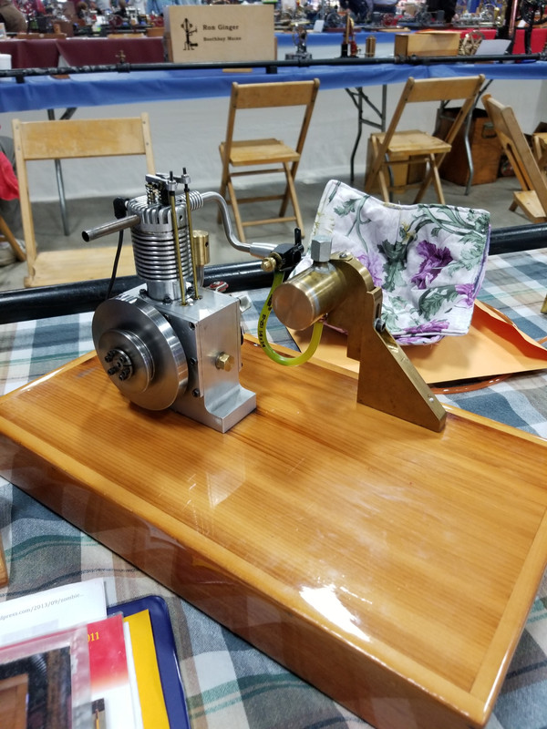
I have been working out in the shop a bit lately. Towards the end of last summer I decided it was time to pull my Hamilton Upshur based vertical single apart and figure out why it was running so bad. This is what I found.
20191006-142735.jpg

20191007-172602.jpg

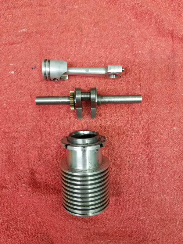
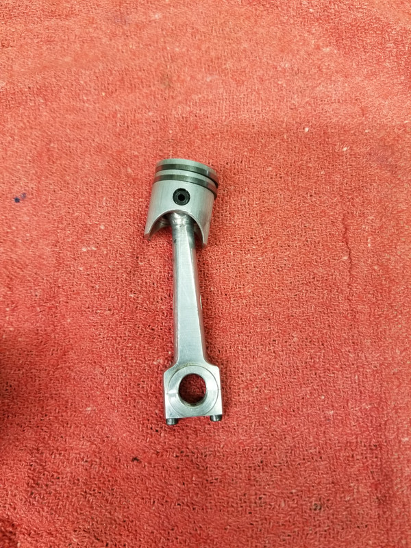
You can see in the first photo the spots on the piston where it was hitting the cylinder & cam. On the cylinder you can see the contact point, there's a matching one on the top side you cant see in the photo. On the crank the rod throw is .003 under on the high points so a new crank is also in order. In the bottom photo you can see the .040" oblong. No fix but a new one there as well. I have made a start on some of this and will post my progress as I am able. I have a link that I posted here soon after joining here.
https://www.homemodelenginemachinist.com/threads/my-first-engine.18599/
I have made a lot of changes over the years, all have made it better or solve self inflicted problems.
Art
 
I turned a blank on on the lathe to make a new cylinder head. I left the diameter and the top oversize, then left the .040" on top to give the valve guides a little extra. The bottom looks like this. The top despite being stranded in the chuck in the rotary table for 5 months I never got a photo of.
20200202-155752.jpg

I did modify the head to give a higher compression ratio. This is why there is a step rather than a flat surface.
When I got my Tormach it came with a Dell PC. When I switched to Path Pilot I couldn't use that PC any more it wasn't compatible. I had a used computer built at 1/7 the price of the Tormach unit. Well in August or September the power supply blew taking the mother board with it. My computer guy had one to replace it but couldn't set it up properly (or understand why I'd want it set up that way). On top of that he was out due to surgery, had a hard time getting caught up with his own stuff much less deal with mine. In the end I drove 3 hours dropped it off for my nephew to look at and took it home with me 3 hours later, two weeks before Christmas.
I used the 4 holes on the bottom surface with screws cut off to locate it and bolted it down through the valve guide holes.
20200121-203045.jpg

This is what it looked after the roughing pass.
Art
 
The next thing I did was to switch to the "high speed spindle" and machine the cooling fins. This is the end result.
20200124-223320.jpg

20200124-223339.jpg

This job took 5 and a half hours...just kidding but I did do a dry run so I did sit and watch the machine for that long. I used a .047" end mill and cut to a depth of .362" 20,000rpm@35 IPM and .0015" per pass. Theoretically Sprutcam thought it should have taken 30 minutes less, but didn't take into account the time it took to slow down going around radius & corners.
I will slowly post what I have done and get you all caught up. I am still pondering how much I want to do, for example I think the rod hitting the cam specifically damaged the exhaust valve but do I want to replace that now or later. I think time will tell as I intend to have it running for the NAMES show.
Art
 
I have made a few other parts like tappets & guides as well as manifolds that I can press into the head and bolt the carb & muffler onto.
20200202-155826.jpg

These are the lifters and guides. I am planning to redo the lifters because I put divots in them when I chucked them on the second side to face them to length.
20200202-155543.jpg

This is the family photo so to speak. With the new & old head side by side. I am missing a photo so I will have to add one later. The aluminum bits are the press fit manifolds that I've done the oval treatment to and drilled & tapped 2-56. this now gives me a platform to bolt on anything on that I can make an attachment for. previously to remove the carb, manifold ect. I had to twist it out with a pliers.
20190426-125113.jpg

This is what it looked like at the 2019 NAMES show. I've had the intake straight out 90 degrees down as designed and as shown in the photo. I only set it up this way cause I didn't like it spitting gas under the carb. More later, please if you have any questions, ask.
Art
 
Hi Just in case anybody is reading this thread say something or I won't waste my time to post a thread here when you can go to MEM and read it. If I get a response and know that someone is actually following along I will catch this site up to where the other is.
Art
 
I've been quiet but I'm certainly following with interest. I am curious, do you know what grade ali the original conrod was made from? I'm thinking I should have a look at some of my older engines (although they don't see much running so hopefully they're ok).
 
i am watching, definitely interested as I am building one right now. please post as many pictures as you can of the whole engine. I appreciate your time in doing this
 
Well, thanks everybody for your outpouring. I will make an effort to keep both forums up to date. Please if you have any questions, ask. When I originally built this I had no Tormach CNC and the only parts done on the Tormach was the cooling fins on the head. I did build the original rod from 6061 aluminum. I purchased a piece of 7075 to make the new one out of, and a piece of bronze for a bearing. Minh Thahn it is from a series of build articles in Strictly I C magazine. Strictly I.C. - Magazine on Miniature Internal Combustion Engines From this website you can order back issues of the magazines with the build article for whatever engine you would like to build. This is what werowance is using to build his engine, although mine is not stock as his is.
Art
 
I made up these manifold inserts so I can just bolt something onto the intake & exhaust manifolds. I set up the rotary table with the three jaw chuck facing up, indicated the part centered in the chuck and ran the program. They are just under .75 on the wide side of the oval and use 2-56 threads. I did use a 3/16 drill inside so the tube wouldn't collapse. I probably should have used lock tite on them but thought of it after pressing them in. Anything I've put in there in the past I destroyed pulling out with a pliers.
20200307_214619.jpg

20200307_214635.jpg

Pressing them worked really well. I used the shank of a 1/4 inch end mill to line up the hole in the head and then a 3/16 drill to line up the manifold and pushed it together in the drill press. More later...
Art
 
Last edited:
Piper,
I'd have to say that I have run this a lot in the 10 or so years I've run it. I have run it for 20 minutes at about 6000 rpm. Although that was long enough for heat to transfer through the short manifold I had on it at that time and melt the plastic Perry carb on it. While it was running well it would run at 7500 rpm. Maybe I should have used heavier oil say 20-50 rather than the 5-30 I have on hand for my modern car. Maybe I should have changed it after every show? It has never overheated and seized. I hope this is helpful and answers your question. As it was designed I don't think it was meant to run that long or that fast. So I think there is a good argument I was running it over it's design specs.
Art
 
Next up was the crank. I had a piece of 1144 so I cut and faced it to length. Mounted it in the v-block indicated it, center drilled the two centers. Then flipped it and repeat. I was then able to use a lathe dog and turn the crank throw.
20200301_135437.jpg

I used a standard 1/16th cutoff tool to rough out the throw for the rod.
Next up was the finishing tool. My grinder is quite wimpy so it took me a while to grind it but it had the radius on it for the stress relief.
20200301_164854.jpg

I have some super finishing cloth I picked up at the NAMES show a while back and used that to finish the crank throw. Then I looked for an appropriate sized spacer to turn the first end of the crank.
20200307_143641.jpg

I needed to do the shorter end of the crank first. Which is why I did the end with the cam gear on it first. I am using a bearing that is metric for the crank this allows me to turn the shaft 5/16" and the bearing diameter 8MM or .315 in inch measurement. Next up was moving to the mill. I set up the rotary table vertical so I could set up the indicator and true it on the X & Y axis.
20200308_143717.jpg

It just barely fit, that is as high as I could go without tripping the limit switch. Then I used a program I designed that is a little more elegant than my original.
20200308_204129.jpg

Then it was back to the lathe to turn the flywheel end of the crank.
20200316_212917.jpg

The main difference in the two cranks is really that I used CAD to help determine where the crank needed to be to be centered, on the crankcase & the cylinder, rather than turning shims to move it one direction or the other. That's the plan at least.
Art
 
Last edited:
Andy,
Thanks, I've got the gear pressed onto the crank so that's done. But I want to turn the blank for the cam. My aim for the weekend is to finish the cam.
Art
 
Back
Top