


DICKEYBIRD
Well-Known Member
- Joined
- Sep 27, 2007
- Messages
- 653
- Reaction score
- 45
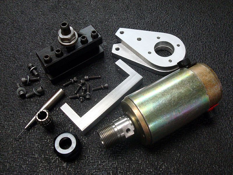
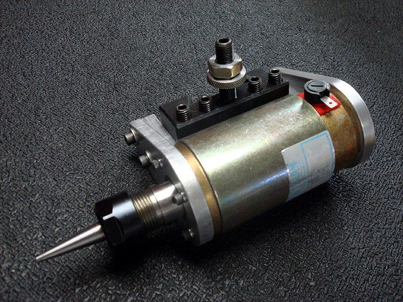
I cobbled up this widget recently from stuff I had lying around. I posted it on another forum but thought maybe someone here might be interested as well.
I built it to save time when making model airplane engine venturis for a friend/customer. The venturis have 4, #58 holes in them and Id been drilling them in the mill using a square ER32 collet block. It worked fine but my mills top speed is a bit slow for the little drill and it required tedious setup for each one.
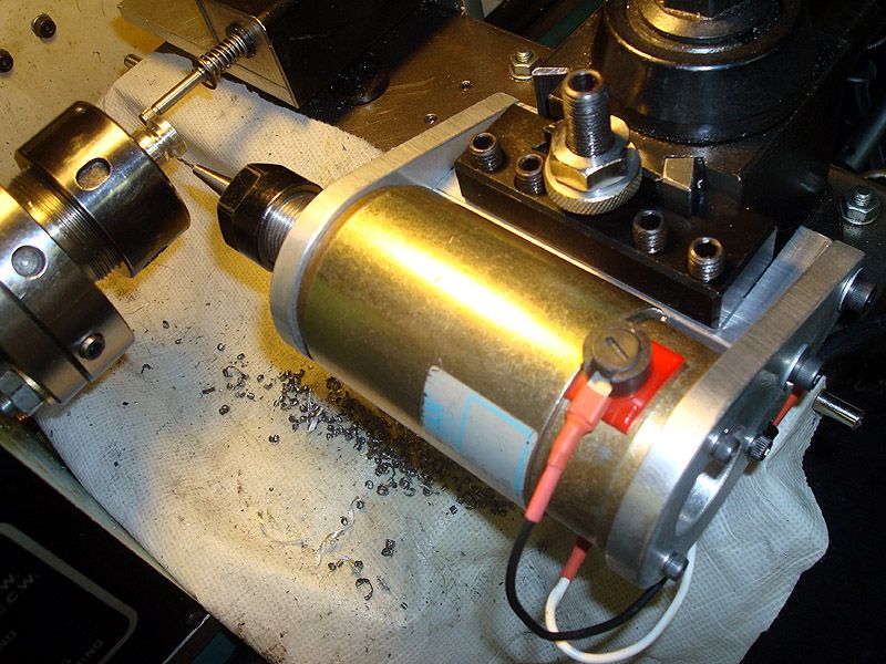
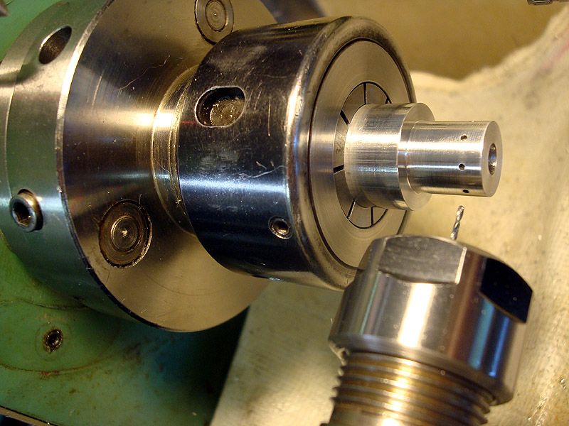
With the part still chucked in the lathe and this hang-on QC drills offsets stored in Mach, its now easy to drill the holes right on the money. I just mark the 4 positions on the chuck flange with a magic marker and use a simple wire pointer to index the holes. Their positioning isnt super critical and theres not enough torque generated from the little drill bit to move the lathe spindle around while drilling.
The motor is a Pittman 24VDC 3450 rpm given to me by forum member Jim Glass, thanks Jim! I run it with a cheap ebay KB speed controller. It came with a Peco add-on board that runs off 36VAC so I used an old 36V transformer to power it. With a few tweaks I got the motor running at a bit under 5000 rpm. Still slow but its twice as fast as the mill & zips through aluminum like butter. I tested it with drills up to 3/16 dia and they work great.
I made an ER16 chuck for it and was going to just press it on the motor shaft but my .3115 reamer somehow made an oversize hole. I drilled & tapped it for 4 setscrews finally got the runout down to .0002.
The last pic shows a test run of 8, #60 holes in a piece of scrap aluminum. The macro lense setting makes the holes look huge but trust me, theyre pretty small!

I built it to save time when making model airplane engine venturis for a friend/customer. The venturis have 4, #58 holes in them and Id been drilling them in the mill using a square ER32 collet block. It worked fine but my mills top speed is a bit slow for the little drill and it required tedious setup for each one.
With the part still chucked in the lathe and this hang-on QC drills offsets stored in Mach, its now easy to drill the holes right on the money. I just mark the 4 positions on the chuck flange with a magic marker and use a simple wire pointer to index the holes. Their positioning isnt super critical and theres not enough torque generated from the little drill bit to move the lathe spindle around while drilling.
The motor is a Pittman 24VDC 3450 rpm given to me by forum member Jim Glass, thanks Jim! I run it with a cheap ebay KB speed controller. It came with a Peco add-on board that runs off 36VAC so I used an old 36V transformer to power it. With a few tweaks I got the motor running at a bit under 5000 rpm. Still slow but its twice as fast as the mill & zips through aluminum like butter. I tested it with drills up to 3/16 dia and they work great.
I made an ER16 chuck for it and was going to just press it on the motor shaft but my .3115 reamer somehow made an oversize hole. I drilled & tapped it for 4 setscrews finally got the runout down to .0002.
The last pic shows a test run of 8, #60 holes in a piece of scrap aluminum. The macro lense setting makes the holes look huge but trust me, theyre pretty small!


