I've done a bit more on this model.
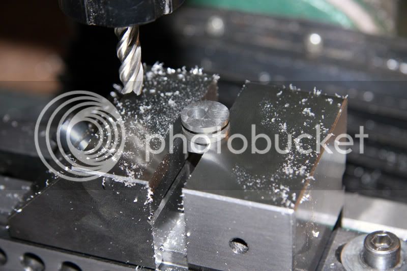
The crank was essentially finished but I needed to face the oposite side of it. I couldn't find a simple way of holding it on the lathe so I just held it flat on the mill and evened the top with an end mill. I then held it sideways and drilled and tapped a 3mm hole for grub screw.
Next was the eccentric insert. It is made of CRS and is probably the most complex bit of machining in this model. I held it on the lathe and made it a close fit to the brass eccentric ring that goes around it. The brass ring came supplied. It only needed to have its edges chamfered.
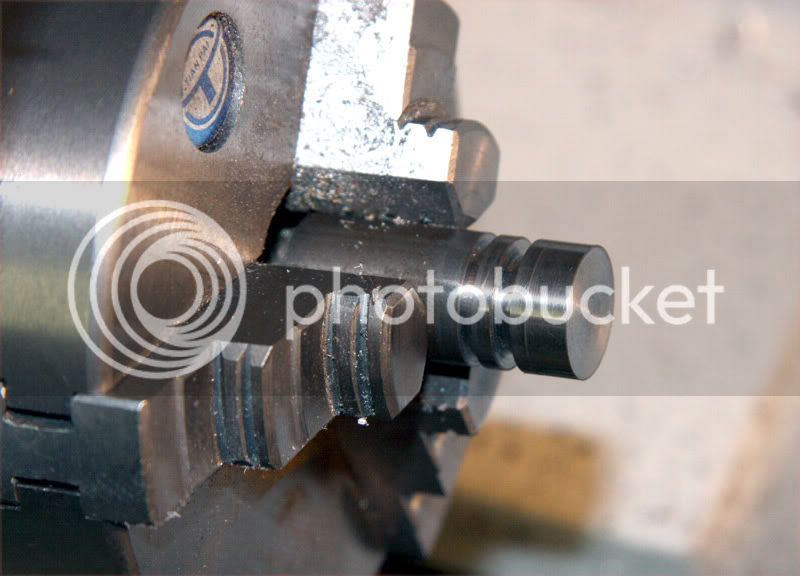
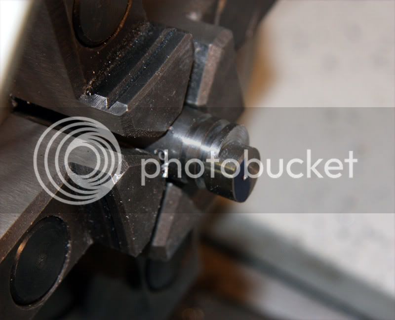
It then needed to have an eccentric hole drilled in it and machined off centre to give room for the grub screw. This was achieved by holding it in the 4 jaw chuck. This was a problem because of the design of my old style 4 jaw. I couldn't get a jaw close enough to the centre of the chuck to hold itt off centre enough. I overcame this by taking a washer off the nut on the back of the jaw. This gave me about 2mm more travel towards the centre- just enough.
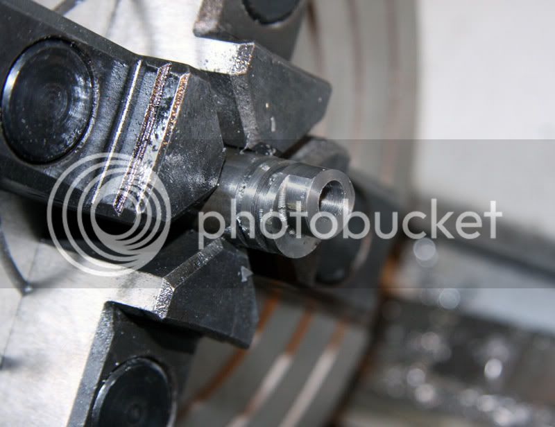
Once the hole was bored to a close fit on the crankshaft I parted it off- by far my least liked process on the lathe.
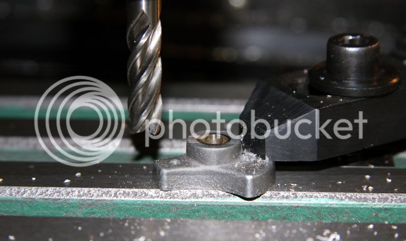
I then held it in the mill and cleaned up the parted off face. I didn't want to hold it in a chuck on the lathe as I didn't want to damage the outside surface.
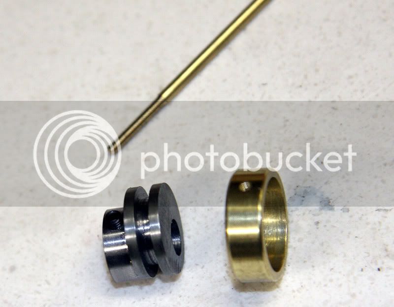
The finished pieces with the eccentric rod partly made.
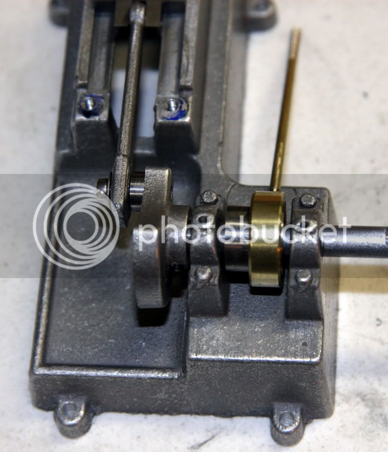
This is all these parts assembled and roughly in place on the model.
There isn't that much more to go- the flywheel and the valve. Hopefully a few more nights and I will have it finished.
You're getting the best of it, Terry.
Next time you need to turn something like that eccentric, and are worried about the chuck jaws
making a mark, cut a small strip from an aluminum can and wrap it around the piece before you
chuck it up.
Thanks guys.
I do plan on painting some of it- at least the base.
Deanofid said:
You're getting the best of it, Terry.
Next time you need to turn something like that eccentric, and are worried about the chuck jaws
making a mark, cut a small strip from an aluminum can and wrap it around the piece before you
chuck it up.
I thought of this but I would still be grabbing it by a very narrow ring of steel. I thought it would be difficult to keep it square in the jaws as I tightened them with the ali around the part.
The mill worked OK.
Not much more to go.
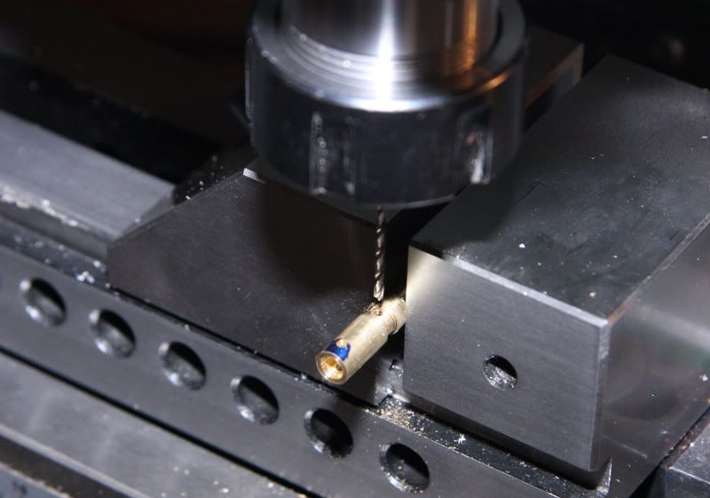
The next part I made was the connector for the valve.
It is a simple bit of machining in brass apart from the part being pretty tiny. It has a small hole drilled in it to connect it to the valve.
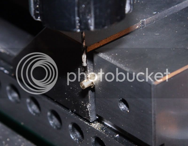
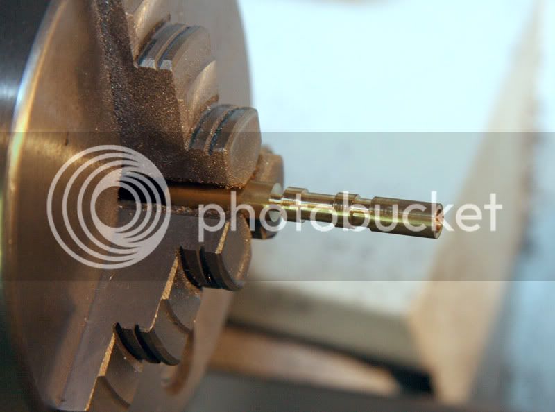
The valve is made from brass and was turned on the lathe. The photo shows it before being parted off. It was then turned around in the chuck and drilled partly through.
It then has a little hole drilled in it to connect the gap in the valve with the hole I had drilled along it's length. I like this design as it allows the exhaust steam to exit out the end of the valve.
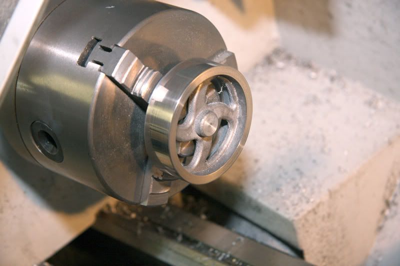
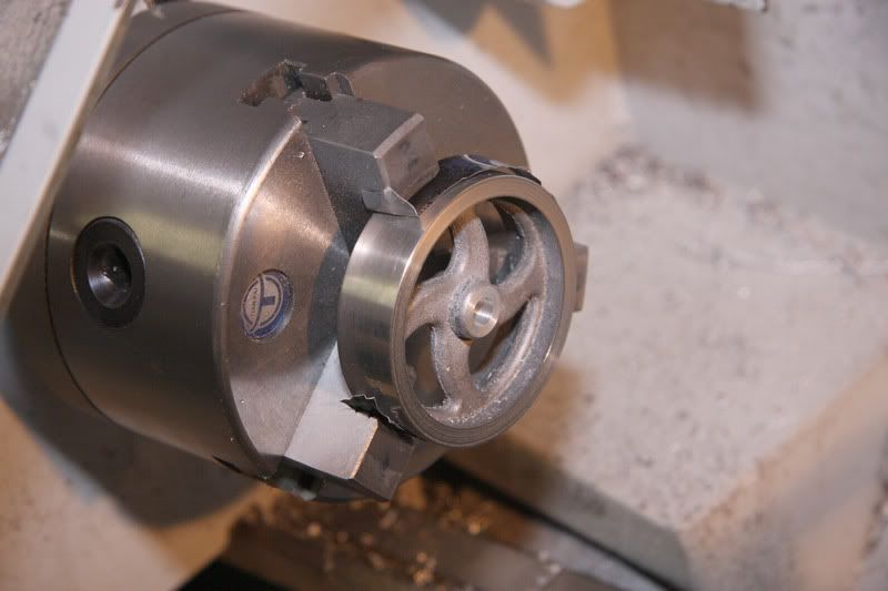
The final part to make was the flywheel. It is a substantial casting made from aluminium.
I just held it in the chuch and machined the outside and faced 1 side.
It was then drilled out and bored to size to fit the crankshaft.
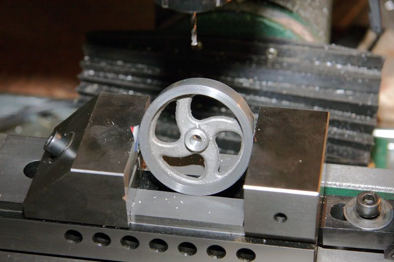
I then turned it around and faced the other side.
The final step was to drill a hole for a 3mm grub screw but holding it at an angle in the mill vice.
Now to wash it all up to remove any oil and paint it. This might take a bit more time compared to the machining ;D
Hopefully I will post an image of the finished engine soon.
It's still coming along great Doc and aside from the cleaning,painting, and polishing its almost a runner. I have no doubt that it will run beautifully, and looking forward to seeing that!!
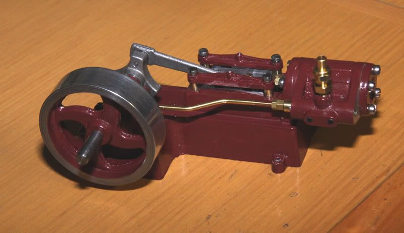
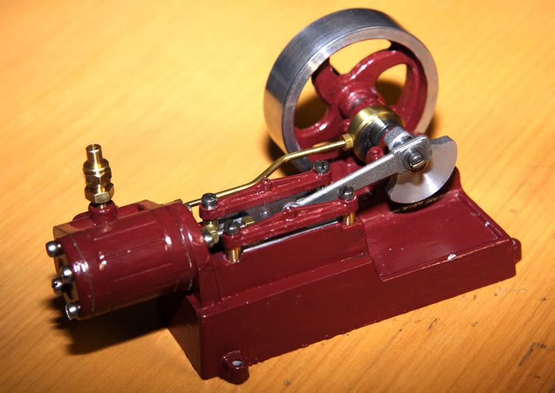
I had a little break form this engine as Christmas intervened. I have put it together and painted it. The paint job needs work as I have chipped it in places when I assembled it. I also need to make a wooden base.
It runs nicly on compressed air. I will make a video soon.
It has been a fun learning experience taking the photos as I go and I may do it again with my next build.
The colour is actually a burgundy colour more like the first photo. The second photo has a colour cast from me underexposing it trying to get more depth of field.
It looks GREAT Terry! A nice wooden base will set it off nicely too. By all means please post a video when you can. Its been a fun thread to watch :bow:


")