PM Research #4 Build Log

Home Model Engine Machinist Forum

Help Support Home Model Engine Machinist Forum:

This site may earn a commission from merchant affiliate links, including eBay, Amazon, and others.

vederstein

Must do dumb things....
Joined
Feb 26, 2011
Messages
917
Reaction score
744
Recently I received a PMR #4 1/4 hp steam engine kit as a gift. Not knowing how to build this thing, I asked if anyone knew of some build logs.

Nobody responded.

So I'm forging ahead. Since apparently there aren't any PMR #4 builds on the Internet (just finished engines), I'll document my build here.

Those that know this engine and it's brother, the #6CI, this is not a model engine. It's a full sized 1/4hp reproduction of an engine from about 120 years ago. So lets face it, you're not going to build this thing on a Sherline or SIEG mini-lathe.

You need some decent sized equipment. Luckily I have a large enough Chinese (Harbor Freight) mill-drill and a 78 year old 12" x 36" Sebastian lathe.

DrillMill004.jpg

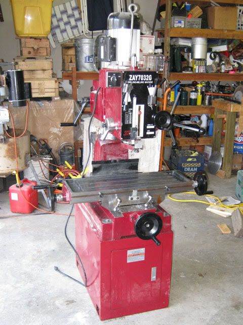
(This isn't mine, but mine looks just like it.)

attachment.php


In 2012 I built the PMR #6CI. This engine uses many of the same components. Unfortunately, with my relative inexperience, a casting issue, and bad decisions at the time, I has a running engine, but it leaked way too much to be of much use.

Perhaps I'll be more successful with this build.

More to come...

...Ved.
 
I started with the base.

It's a cast iron non-critical part, so it's a good starting place to see how the CI cuts.

DSC01150.jpg


DSC01151.jpg


DSC01155.jpg


DSC01156.jpg
 
Then I started on the Frame.

DO NOT DO WHAT I DID HERE!!!

The first operation, facing the legs went ok.

The second operation (turning the OD of the Cross Head) was difficult to center, but I got there.

The third operation (facing the cross head) is where all hell broke loose. The part wasn't held good enough in the chuck and flew out. The casting hit the back wall, then the floor. The leg broke off.

I tried welding the legs back on, but no luck. I have the part re-ordered, the that's a $100 U.S. dollars down the drain.

I guess I'll have to figure out something else when I try this part again.

DSC01158.jpg


DSC01159.jpg


DSC01160.jpg
 
After my dismay at the Frame. I went onto the Cylinder, Steam Chest, and caps.

First the caps. Then the Cylinder. Finally, I transfer punched the hole locations from the Caps to the Cylinder.

In the last picture in this post, you can see my totally botched Frame in the background.

DSC01170.jpg


DSC01174.jpg


DSC01175.jpg


DSC01176.jpg


DSC01179.jpg


DSC01180.jpg


DSC01161.jpg


DSC01164.jpg


DSC01165.jpg


DSC01166.jpg


DSC01168.jpg


DSC01181.jpg


DSC01182.jpg
 
Great build. Love the clear pics. Keep em coming please.
 
Hi There

Sorry I was absent from this site for some time

When I ordered my kits I was very much tempted to build #4 as well, but I got the 6CI instead. #4 is the vertical brother of #6 just as you said, however many of the parts are the same and same in size so that should be easy for you.

I am on the brink of completing #6, just over 4 month in my spare time. Then it will be the Red Wing. I called mashining of #6 a "walk in the park" which obviously was not the case, but will be compared to the Red Wing

I also built #5 with Boiler 2 and #1

Where are the leaks on your #6?

From your photos you are doing a great job here

Keep it up and all the best.

You are also welcome to mail me on [email protected]
 
Hi There

Where are the leaks on your #6?

Albert,

Here's the list of issues (mostly my fault and inexperience) from my #6CI build:


  1. The main bearing caps were not aligned. I finally realized the problem long after I completed the engine. When I initially machined the base, I clamped the casting to the bed of the mill and machined the face. The casting was a bit warped, and when I unclamped it, it sprung back to its original position warping the machined surface.
  2. To maintain straightness on the crankshaft, I bored a slip fit to the shaft when pressing on the crankshaft journal. Then I knurled the mainshaft and pressed them onto the crank plates. The knurled press fit didn't hold. Eventually I has to cross drill the shaft and press in a pin.
  3. My connecting rod casting was quite warped from PMR. I straightened it with some persuasion (hammer) before I machined it.
  4. The steam chest portion of the cylinder casting had a significant sink in it. In the end I made a sleeve and held it in with JB weld, but that is the source of my leakage. The engine runs on 15-20 psi, but there's so much leakage through the steam chest, that I cannot really use the engine for any real purpose.
I really hope this build of the #4 turns out better.


I have a large enough boiler to make some real power, I just need an engine that is good for it.


Thanks,


...Ved.
 
Another Sunday, more progress on the engine:

I received the replacement frame. The entire day was devoted to it. I went slowly. I have no desire to blow another $100 on another scrapped casting.

Since the facing of the legs went ok last time, I used the same setup except I extended my live center to give some support:

DSC01183.jpg
 
After about 1-1/2 futile hours of trying to mount this thing to my 4-jaw chuck and/or my 8" faceplate, I gave up and decided to use the engine's base as a jig to mount the frame for machining:

DSC01184.jpg


DSC01186.jpg


DSC01187.jpg
 
Now, cast iron as an engineering material is great in compression. It's fair (at best) in tension and sucks in bending. It can be quite brittle.

So I backed up the base casting with some temporary supports prior to chucking into the lathe:

DSC01188.jpg
 
And with that casting re-enforcement, it's off to the races!!!!!

(The bar in the bore during the facing operation was just a safety in case the part became dislodged like how I ruined the first Frame casting.)

And that's it for this week.

DSC01189.jpg


DSC01190.jpg


DSC01191.jpg


DSC01195.jpg


DSC01196.jpg
 
Albert,

Here's the list of issues (mostly my fault and inexperience) from my #6CI build:


  1. The main bearing caps were not aligned. I finally realized the problem long after I completed the engine. When I initially machined the base, I clamped the casting to the bed of the mill and machined the face. The casting was a bit warped, and when I unclamped it, it sprung back to its original position warping the machined surface.
  2. To maintain straightness on the crankshaft, I bored a slip fit to the shaft when pressing on the crankshaft journal. Then I knurled the mainshaft and pressed them onto the crank plates. The knurled press fit didn't hold. Eventually I has to cross drill the shaft and press in a pin.
  3. My connecting rod casting was quite warped from PMR. I straightened it with some persuasion (hammer) before I machined it.
  4. The steam chest portion of the cylinder casting had a significant sink in it. In the end I made a sleeve and held it in with JB weld, but that is the source of my leakage. The engine runs on 15-20 psi, but there's so much leakage through the steam chest, that I cannot really use the engine for any real purpose.
I really hope this build of the #4 turns out better.


I have a large enough boiler to make some real power, I just need an engine that is good for it.


Thanks,


...Ved.

Hi There Ved

Thanks for your response.

I had a similar problem with the base so I did not clap it down. I've machined the bearing clocks clamped together in the milling machine, made bushes for the crank and upon reaching .001 in size I mounted them on the frame, super grued and then drilled, tapped and fitted, which turned out a perfect alignment.

If you missed my posts:
http://www.homemodelenginemachinist.com/showthread.php?t=24595&page=2

I notice you do not use a back plate in the lathe which I think is important to clamp castings in those funny shapes we find ourselves trying to clamp.

What I also like to do when it comes to fitting eg heads, inside heads or bearing blocks are the following steps:

I Clamp items in machine vise or stepper blocks with bolts, glue the parts together lightly with super glue, locate centers, drill centre drill, drill through the thread sizes, drill hole size to meet required depth and then tap, all in one position in the milling machine, I the repeat the steps for all holes. This ensures accurate drilling and tapping, also preventing the taps to start scew treading. I also put in the screws as I go along.

On the cylinder I used a back plate to clamp it in the lathe, boring both the cylinder bore and the valve chest. I prefer not to drill and reem as per plan. I made a boring bar for the valve and the result was a perfect fit with no leak. You may consider re boring it and making a purpose fit valve for it.

My connecting rod was rather a misaligned casting on which I had to do a lot of work grinding and sanding it till aligned, turned out to be fine, but a lot of work I can assure you, #4 uses the same rod correct?

I am very interested in your boiler, that one thing I must still consider building. Do you mind sharing it with me?

Until next time Happy machining!!

Albert
 
First of all, I apologize that many of these photos aren't as clear as the previous photos. The camera I was using ran low on power, so I used my wife's camera. It's actually a better camera, but apparently not in action shots.

Now this engine has lots of round things. So today was quite circular.

First, the lower valve heads:

DSC01197.jpg


DSC01198.jpg


DSC01199.jpg


DSC01200.jpg


DSC01201.jpg


DSC01202.jpg


DSCN0094.jpg
 
The piston rod gland nut is kind of tricky. I don't have a 1/2-20 die, so I single pointed the thread. I don't single point very often, but in this case is went ok...

DSCN0107.jpg


DSCN0113.jpg


DSCN0116.jpg
 
Ahh, Crank Plates - stepping away from brass, which is a treat to machine and back to cast iron which is grainy, dirty, and not particularly pleasant.

After the lathe work, I took the parts to my mill. Two issues arose. First, my rotary table with 3" chuck is too small to hold the crank plates. So I bit the bullet and cut a piece of 5/8" brass bar stock to fit a pin upon which the crank plates would slip fit onto.

The other issue is that my mill/drill is a round column. So my Z-axis travel wasn't enough to fit the drill and/or reamer. Raise the column and I lose my centering on the rotary table. Several years, I took a Bison 2" chuck and made a little stud on the back that I can use for these occasions.

And that concludes week 3.

...Ved.

DSCN0117.jpg


DSCN0119.jpg


DSCN0120.jpg


DSCN0122.jpg


DSCN0124.jpg


DSCN0125.jpg


DSCN0127.jpg


DSCN0128.jpg


DSCN0130.jpg


DSCN0132.jpg
 
Great machining there Ved

At this rate you will finish soon!!
 

Latest posts

Back
Top