Pile Driver

Home Model Engine Machinist Forum

Help Support Home Model Engine Machinist Forum:

This site may earn a commission from merchant affiliate links, including eBay, Amazon, and others.
So there we have it. A gear reducer mount, in all its splendor!!! (even with a collection of funky bolts holding things together.) I think that was the hardest part to do, and mill troubles aside, it was actually quite easy.
MOTORMOUNT-2.jpg

MOTORMOUNT-1.jpg
 
Now 2 hubs are finished and the sprockets welded to them. Thats enough machining for today. Its a beautifull hot summers day out, and wife and grandkids are due to return from strawberry picking about now, so I had better clean up and get out of the shop!!!
003-4.jpg

002.jpg
 
After a nice drive in the countryside, and a dinner with MANY fresh strawberries (YUM YUM) I snuck back down to the shop and whittled out a pair of driveshaft bushings,---then found out that my digital camera batteries were too dead to operate the flash---
DRIVESHAFTBUSHINGS.jpg
 
Today was another beautifull summers day, about 85 degrees and low humidity. I dashed down to the shop 2 or 3 different times and managed to carve out the top piece for the main housing. The inside radius was a bit tricky, and I didn't feel like mounting the rotary table. I "fudged" it out with the bandsaw and finished it with a half round file. The inside won't show anyways when its all assembled. Now I have to go wash the hotrod and get ready for "cruise night" at the local Burger King.
TOPOFHOUSING002.jpg
 
You are making some fine progress on it Brian... and its really going to be a unique thing to watch in combination with one of your engines. Still following along here. Nice fix on the mill to BTW :)

Bill
 
Interesting model I will be following. I watched a documentry about a diesel hammer once, two stroke no crank just a piston, cylinder and gravity. This shoud look great when running.
Brock
 
Thanks for the comments guys. It will certainly be unique. I haven't played with these magnets before, so I think it will be very interestng. If it works the way I hope it will, people are going to be quite puzzled at how the drop hammer moves back up to the top of the column with no physical link visible.
 
This morning I got up and decided to build the base, which everything bolts to. You will see that I didn't put in the 5/8" counterbore that the drawing calls for.---I'm going to wait untill everything is assembled, just to make certain its concentric with the "pile" when everything is together.
BASECOMPLETED.jpg
 
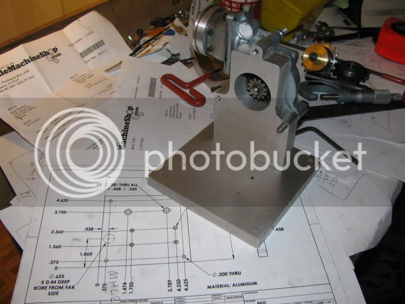
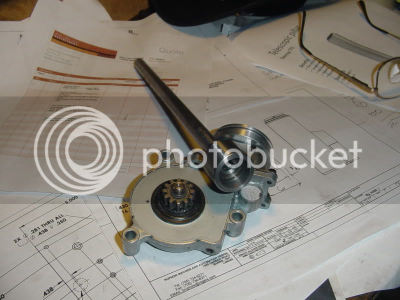
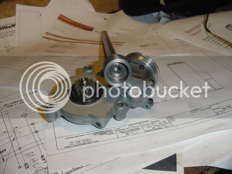
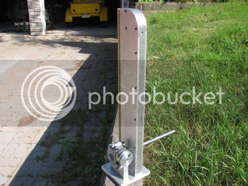
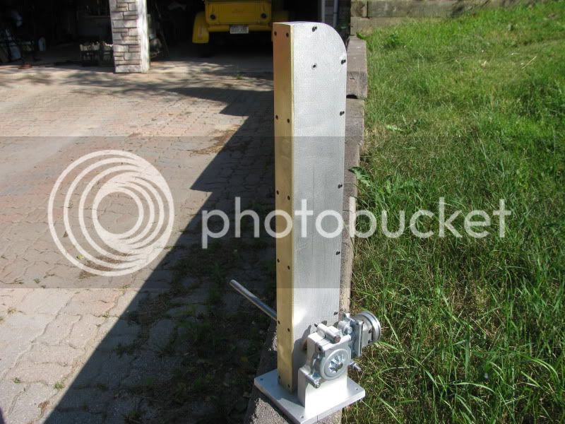
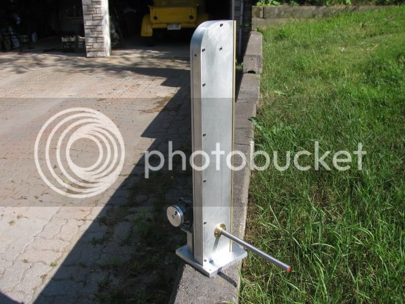
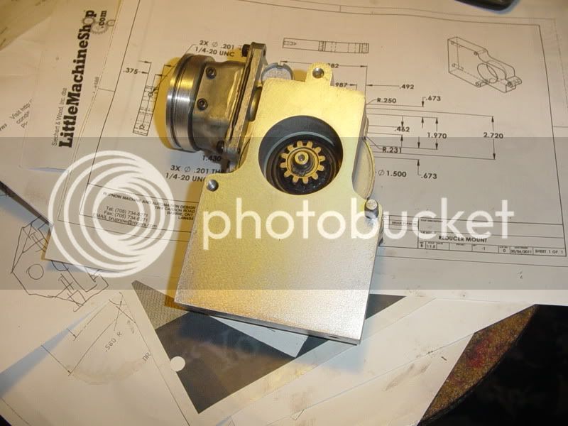
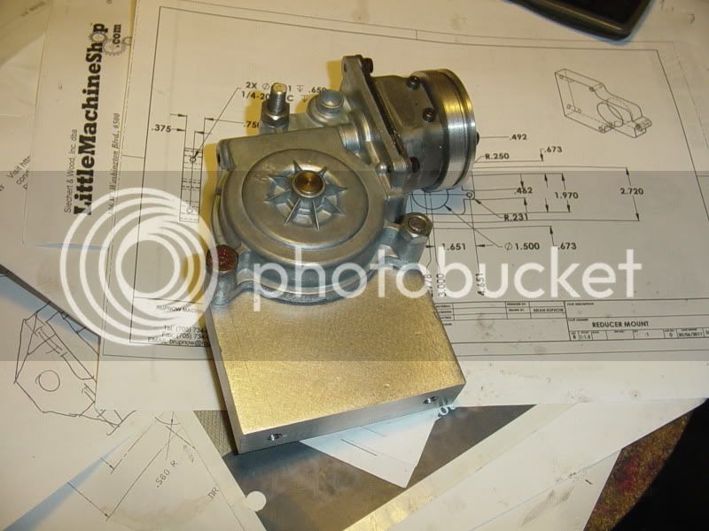
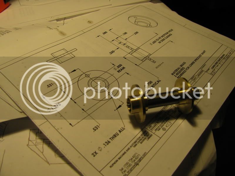
I anticipate a world of joy in making a coupling between my gear reducer and the lower sprocket shaft. The strange thing is that the gear revolves, but the bit of shaft you see sticking out past the face of the gear doesn't. I haven't tried to take the gear off yet, and if I do get it off, I may see a clear solution. Otherwise I will use a coupling on the end of the sprocket shaft, with 2 counterbores in it, one to fit the .312 dia. stub shaft and one at .850 which is the outer dia. of the gear. I will drill and tap the sides of the large counterbore for 3 pointed set-screws at 120 degrees apart and let them be what transfers the rotation of the gear to the sprocket shaft.
 
Brian,
re your
"People also liked the Pumpjack oil pumping model which I designed, built, and posted.(although I haven't seen anyone else build one)."

Here's one complete with your Horizontal Twin powering it.. :bow:

[ame]http://www.youtube.com/user/deadin391#p/a/u/0/6sygYpkqju0[/ame]
 
This morning I got up and drilled a pair of holes 16.5" apart in a wooden board and cut the roller chain to length and assembled it to check my hole centers. The centers are okay, but I notice that the hole in my top sprocket bushing is not concentric with the bore of the sprocket. I'm not sure how I managed that, but will make a new brass bushing and drill/bore/ream it in place in the lathe.I actually went so far as to hook a cordless drill on the driveshaft, and yep---everything goes round and round, just like its supposed to!!!
IMG_1432.jpg
 
I think this driveshaft is going to work okay!!! The large bore is a "good fit" over the gear. The smaller internal reamed hole is a "good fit" on the 5/16" stub that sticks out past the face of the gear. I just counted the teeth on the gear, and it seems have the choice of using either 2 or 4 set screws thru the outer shell as "drive dogs" to transfer the rotation from the gear to the driveshaft. I had no design work when I started this project, now suddenly I have one new job and one existing job "off hold". Hopefully I can keep up my momentum.
DRIVINGSHAFT001.jpg

DRIVINGSHAFT002.jpg
 
tel said:
Well, there is this one, which I still haven't got around to finishing off.


Very nice, Tel!!! I assume you are going to power that one with the Kerzel----Right??? (Meow----meow!!!!)
 
This morning I got my non concentric bushing removed and replaced in the driven sprocket. This afternoon I made up the main "spine" that the two sideplates bolt to.
CHAIN-SPROCKETS-BACKBONE002.jpg
 
A lot has been accomplished in the last couple of days.---And the good news is, all the pieces bolt together!!! I take that as definitly being a good sign, because I hate having to "stretch" hole positions. And there are a LOT of bolts. The driveshaft turns freely, although I have yet to add the set screws to act as drive keys to tie it to my gear reduction unit. Both sprockets and the chain are mounted inside the housing. The chain is a bit slacker than I wanted it to be, but it turns relatively slowly and I'm not sure yet if I will do something to move my top sprocket shaft up a bit higher or not. I still have to make the slider and the "drop hammer" for it, and make my pieces which tie the magnets to the roller chain. The assembly shown in these pictures was a "trial fit" to make sure everything fit together properly. Now I have to tear it down to finish the rest of it, but at least I know it will all go back together.
IMG_1441.jpg

IMG_1440.jpg

IMG_1439.jpg
 
The magnet going down next to that brass plate is going to slow down the pile due to eddy currents. Try to drop a magnet in a non ferrous pipe and you will see the effect.
 
Noitoen said:
The magnet going down next to that brass plate is going to slow down the pile due to eddy currents. Try to drop a magnet in a non ferrous pipe and you will see the effect.

True, but it may add some Visual Mystification, leading to a scientific conversation on magnets and eddy currents.

Kel

 
Noitoen said:
The magnet going down next to that brass plate is going to slow down the pile due to eddy currents. Try to drop a magnet in a non ferrous pipe and you will see the effect.
The magnet next to the brass plate will be going up!!! Thats what lifts the pile-driver head. After the magnet passes over the sprocket to the other side, gravity will pull the pile driver head down in free fall.
 
I was talking about the magnet on the "hammer"
 
Back
Top