PatRon: Harmonically Reciprocating Piston Rotary Engine

Home Model Engine Machinist Forum

Help Support Home Model Engine Machinist Forum:

This site may earn a commission from merchant affiliate links, including eBay, Amazon, and others.

manolis

Well-Known Member
Joined
Jul 18, 2016
Messages
88
Reaction score
38
Hello all.

Here :

PatRon2.gif


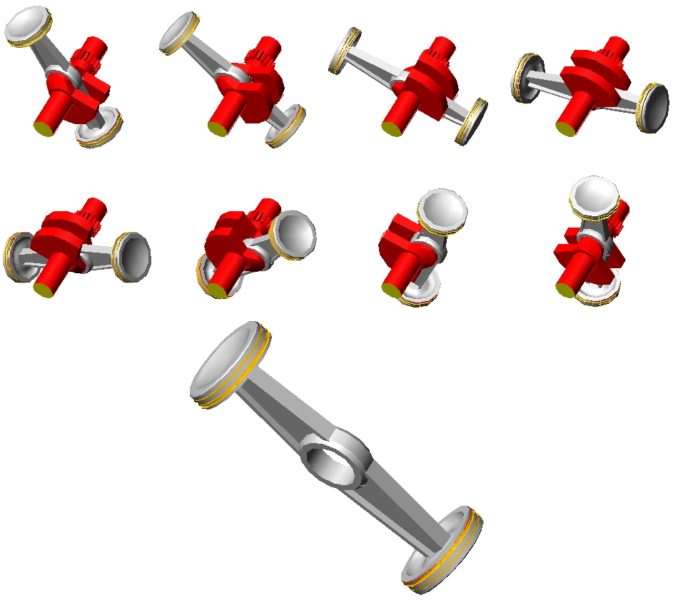
is a PatRon Reciprocating-Piston Rotary-Engine.

PatRon1.gif


It comprises a crankshaft, a piston rotatably supported on a crankpin of the crankshaft, and a rotating cylinder wherein the piston reciprocates sealing one side of a combustion chamber.

For a complete reciprocation of the piston inside the cylinder they are required two rotations of the crankshaft.

Without external balance shafts, the balancing of the inertia force, moment and torque is perfect (even for the single cylinder).

PatRon11.gif


A synchronizing gearing keeps the cylinder rotating at the same direction with the crankshaft and at half angular speed than the crankshaft; the high pressure gas in the combustion chamber does not load the synchronizing gearing.

Not only the power passes directly to the load and the synchronizing gearing remains unloaded but, additionally, the cylinder liner remains rid of thrust loads. Think how.


The stroke S of the piston along the cylinder equals to four times the distance between the (fixed) rotation axis of the crankshaft and the (fixed) rotation axis of the cylinder.

The relation between the displacement D of the piston along its cylinder and the rotation angle f of the crankshaft is like:

D=(S/2)*sin(f/2)

which is a pure sinusoidal (or harmonic) motion.

PatRon4.gif


With the PatRon:

* the power passes directly to the load (more directly than in the conventional reciprocating piston engines: there is no connecting rod (the piston is rotatably mounted directly on the crankpin), there are no thrust loads on the cylinder liner),

* the synchronizing gearing remains unloaded by the high gas pressures during the compression - combustion – expansion,

* the two halves of the "immovable" casing (one per side of the spinning cylinder) are easily coupled / bridged forming a space wherein the cylinder spins safely,

PatRon10.gif


* only one crankshaft is required (and only a set of balance webs secured on the crankshaft for the complete balancing of the engine),

* there are no high speed bearings loaded by heavy inertia loads,

* in case of air-cooling the rotation of the cylinder simplifies things (the cylinder is also the fan),

* if desired, the power can be delivered by the rotating cylinder (which spins at half crankshaft speed),

* it is for single acting, for double acting pistons, even for “multi-acting” single-piece pistons,

* it is for two-stroke and four-stroke engines, etc


For more: http://www.pattakon.com/pattakonPatRon.htm


In a few words:

The PatRon brings the good sealing and the small surface to volume ratio of the reciprocating piston engines in the rotary engines, without introducing significant side effects.


Thoughts?

Objections?

Thanks
Manolis Pattakos
 
So your synchronising gear isn't loaded by the combustion gas, but it is heavily loaded by having to drive the rotating mass of the crankcase/s so I see little point in mentioning that. Then you have the crankcase/s assemblies being rotated, which robs the engine of a significant amount of power, far more than required to drive a simple cooling fan (which is a far simpler set-up than a rotating crankcase so no point in mentioning that 'fact' either). And this engine suffers from the same gyroscopic effect problems that plagued other rotating cylinder engines, which was one of the reasons this type of design was rejected so many years ago.

So in a nutshell you've 'solved' the problem of piston side thrust robbing some reasonably small amount of engine power by using a massive amount of engine power to rotate the crankcase, whilst also introducing other negative effects. I think that's significant side effects...
 
Hellow Herbiev

You write:
“Have you started building this ?”

We have some harmonic engine prototypes (look at http://www.pattakon.com/pattakonPPE.htm#harmonic ).

The modifications required to go from the Harmonic to the PatRon are not so many.

A two stroke is preferable for start.

Thanks
Manolis Pattakos
 
Hello Gogsy

You write:
“So your synchronising gear isn't loaded by the combustion gas, but it is heavily loaded by having to drive the rotating mass of the crankcase/s so I see little point in mentioning that.”

You are wrong.

As in the Wankel rotary engine, the synchronizing gearing remains unloaded as long as the engine operates at constant revs.

Only when the revs increase, there is a small load on the teeth of the synchronizing gearing (this load accelerates the cylinder of the PatRon or the rotor of the Wankel).

The loading gets high only during fast decelerations (braking) with the engine: say you go with 100mph and fifth gear, put third gear and leave the clutch to engage.

This loading happens during the engine braking with an RX8 Wankel, too. But in the Wankel case, the momentum of inertia of the rotor is high and the loads on the teeth proportionally higher.


If it is comfusing, let me know to further explain.


You also write:
“Then you have the crankcase/s assemblies being rotated, which robs the engine of a significant amount of power, far more than required to drive a simple cooling fan (which is a far simpler set-up than a rotating crankcase so no point in mentioning that 'fact' either). And this engine suffers from the same gyroscopic effect problems that plagued other rotating cylinder engines, which was one of the reasons this type of design was rejected so many years ago.”


Please look at this drawing:

PatRon6.gif


and think again about “the increase in rotating mass”, about the aerodynamic losses and about the “gyroscopic effect problems”.

What I see is a thin lightweight (because, among others, it is rid of bending loads) aluminum cylinder comprising the central part of the propeller.


Thanks
[FONT=&quot]Manolis Pattakos[/FONT]
 
You write:
“So your synchronising gear isn't loaded by the combustion gas, but it is heavily loaded by having to drive the rotating mass of the crankcase/s so I see little point in mentioning that.”

You are wrong.

As in the Wankel rotary engine, the synchronizing gearing remains unloaded as long as the engine operates at constant revs.

So the synchronising gear is UNLOADED at constant RPM you say, so somehow your wonder engine is completely frictionless and suffers no drag as it revolves the cylinder. So the engine doesn't need to make any power to maintain constant RPM, therefore no fuel is consumed. Wonderful, you've perfected perpetual motion - I see a Nobel prize in your future!

You also write:
“Then you have the crankcase/s assemblies being rotated, which robs the engine of a significant amount of power, far more than required to drive a simple cooling fan (which is a far simpler set-up than a rotating crankcase so no point in mentioning that 'fact' either). And this engine suffers from the same gyroscopic effect problems that plagued other rotating cylinder engines, which was one of the reasons this type of design was rejected so many years ago.”


Please look at this drawing:

PatRon6.gif


What I see is a thin lightweight (because, among others, it is rid of bending loads) aluminum cylinder comprising the central part of the propeller.

Firstly, you never mentioned the intended application was an aircraft engine. However, if it is to be used as an aircraft engine there is absolutely no need to have the engine acting in place of a cooling fan, a traditional propeller on a normal radial engine acts as a very efficient fan. On your design, movement of the aircraft itself would provide airflow. So again, this 'benefit' is meaningless.

Secondly, radial engines suffer from greatly increased drag than say a cowled engine (I suspect from your frictionless theories above you've failed to take this into account) which again is a huge unnecessary drain on engine power.

Thirdly, you say your design is lightweight because it is free of bending loads, yet your drawing shows the working surfaces of the propeller blades outboard of the ends of the engine. Unless these propeller tips are made of the same miracle frictionless material your engine is, there will be SIGNIFICANT bending loads on your cylinders to drive the propeller. If the propeller is frictionless then it is rather pointless as it will not provide any thrust to the aircraft.

Finally, it stands to reason that ANY increase in rotating mass, especially when coupled with an increase in moment of inertia, will have greater gyroscopic effect. Surely you're not claiming your engine will have less mass than the centre section of the propeller that it replaces in your drawing?

If you were interested in simply making/designing model engines I wouldn't be concerned about your designs at all. However you are seemingly trying to promote your ideas as wonder-designs with real world applications using pseudo-science and I think you need to be called out on it.
 
Hello Cogsy

You write:
“So the synchronising gear is UNLOADED at constant RPM you say, so somehow your wonder engine is completely frictionless and suffers no drag as it revolves the cylinder. So the engine doesn't need to make any power to maintain constant RPM, therefore no fuel is consumed. Wonderful, you've perfected perpetual motion - I see a Nobel prize in your future!”


Allow me to keep the discussion “strictly technical”

Here is the single cylinder PatRon of the animation at 90 crankshaft degrees (and 45 cylinder degrees) after the TDC.

At right the piston and the crankshaft are sliced to show the small gear of the crankshaft.

PatRon_Loads.gif


The high pressure gas inside the combustion chamber applies a force F1 (black arrow) on the piston crown.
Due to the geometry of the design, this force necessarily passes from the center of the crankpin.

An equal and opposite force –F1 (red arrow) is applied by the high pressure gas onto the cylinder / cylinder head.
Due to the geometry of the design, again, this force –F1 passes from the rotation axis of the cylinder.


At the intersection of the three axial lines (dash dot lines) is where the rotation axis of the crankshaft and the rotation axis of the cylinder intersect the plane of the drawings.

PatRon14.gif


When the load is driven by the crankshaft, the torque M1 of the force F1 relative to the rotation axis of the crankshaft is applied on the load (which, in turn, applies an equal and opposite torque –M1 on the crankshaft).


Do you understand now why the synchronizing gears are not loaded?


Quote from http://www.pattakon.com/pattakonPatRon.htm :

“The driving of the propeller by the cylinder (and not by the crankshaft) causes the loading of the synchronizing gearing (in the specific case the synchronizing gearing acts as a reduction gearing, too).”

I hope everything is clear now.


Thanks
[FONT=&quot]Manolis Pattakos[/FONT]
 
Do you understand now why the synchronizing gears are not loaded?


Quote from http://www.pattakon.com/pattakonPatRon.htm :

“The driving of the propeller by the cylinder (and not by the crankshaft) causes the loading of the synchronizing gearing (in the specific case the synchronizing gearing acts as a reduction gearing, too).”

So the extra mass of the propeller being driven by the crankcase actually introduces a load to the synchronising gear (as per your quote above), and yet the mass of the crankcase WITHOUT the propeller does not require any driving so the synchronising gear is completely unloaded (as per your 'strictly technical' explanation above)?? You're back to claiming the crankcase is engaging in perpetual motion (hogwash). If your engine can run without any load on the synchronising gear (unless the propeller is attached to the crankcase) then you could mount the propeller to the crankshaft and do away without the synchronising gear altogether - it just wouldn't be required at all.
 
Hello Cogsy

You write:
“So the extra mass of the propeller being driven by the crankcase actually introduces a load to the synchronising gear (as per your quote above), and yet the mass of the crankcase WITHOUT the propeller does not require any driving so the synchronising gear is completely unloaded (as per your 'strictly technical' explanation above)?? You're back to claiming the crankcase is engaging in perpetual motion (hogwash).”


No.

If the propeller is driven by the crankshaft (either directly or through a reduction gearing) then the synchronizing gearing of the PatRon remains unloaded.

Think simply:

When a mass moves at constant speed in the empty space (linear motion), no force is required to keep its motion for ever (one of Newton’s laws).
Similarly when a mass spins about an axis at constant speed in an empty space, it does not require torque to keep its rotary motion for ever.
And it doesn’t matter how big is the mass of the spinning body.
Only if there is a resistance in the motion of the rotation of the mass (like the air friction), only then a torque is required.


You also write:
“If your engine can run without any load on the synchronising gear (unless the propeller is attached to the crankcase) then you could mount the propeller to the crankshaft and do away without the synchronising gear altogether - it just wouldn't be required at all.”

Now you start talking “strictly technical”.

If you eliminate the friction of the bearings by which the cylinder is rotatably mounted to the casing (or basis) of the engine, if you also eliminate the aerodynamic friction relative with the spinning, in the air, of the cylinder, then yes, for as long as you keep the rpm constant, the synchronizing gearing can be removed without problem, no matter how strange it seems to you.


Thanks
[FONT=&quot]Manolis Pattakos[/FONT]
 
Think simply:

When a mass moves at constant speed in the empty space (linear motion), no force is required to keep its motion for ever (one of Newton’s laws).

I'll put it as simply as I can - Your engine is not frictionless and it is NOT OPERATING IN A VACUUM. Therefore, the crankcase will be losing energy as it is rotating, therefore it requires the synchronising gear to provide more energy and the gear cannot remain unloaded. It's basic schoolboy physics and your attempt to persuade people otherwise is the pseudoscience I was talking about.

Meanwhile, all your other contradictions remain unresolved, such as the super lightweight cylinders because there's no bending forces (excluding that pesky aerodynamic drag thing again) except of course the huge bending forces introduced by the propeller blades in your image.
 
Hello Gogsy

You write:
“I'll put it as simply as I can - Your engine is not frictionless and it is NOT OPERATING IN A VACUUM. Therefore, the crankcase will be losing energy as it is rotating, therefore it requires the synchronising gear to provide more energy and the gear cannot remain unloaded. It's basic schoolboy physics and your attempt to persuade people otherwise is the pseudoscience I was talking about.

Meanwhile, all your other contradictions remain unresolved, such as the super lightweight cylinders because there's no bending forces (excluding that pesky aerodynamic drag thing again) except of course the huge bending forces introduced by the propeller blades in your image.”


In order a propeller rotating at constant speed, say at 5,000rpm, to absorb a power of, say, 50HP, a constant torque of 70mN (50lb-ft) is required to be applied on it.

In order a 4-stroke single-cylinder conventional engine to provide the 70mN constant torque (mean torque), the maximum (instant) torque on the cylinder-casing of the engine is some 10 times higher.

This plot is from Taylor’s book “The Internal Combustion Engine in Theory and Practice”

Taylor_Torque_vs_Crankangle.jpg


The peak instant torque caused by the high pressure gas inside the cylinder is some 8 times higher than the mean torque.

If you take into account the inertia torque, things get even worse: the peak instant torque gets, say, 15 times higher than the mean torque provided by the engine.

For simplicity, take the peak instant torque as 10 times higher than the mean torque provided by the 4-stroke single cylinder engine.

How this torque is generated?

It is the thrust force the piston skirt applies to the cylinder liner times the eccentricity of the piston skirt from the crankshaft rotation axis.

So, the cylinder-casing of the conventional single cylinder has to be adequately robust to receive a ten times higher torque than the mean torque received by the propeller.

The one torque belongs to a different order of magnitude than the other.

I hope the previous answer some of your questions.


With the PatRon (here is a two cylinder 2-stroke):

PatRon15Fast.gif


the cylinder is rid of thrust loads.

So, no lubricant is required between the piston and the cylinder to take thrust loads (because there are no thrust loads).

Oil (lubricant) is required only between the piston rings and the cylinder liner.

According Lab tests published in the internet, this oil film can be some five times thinner than the required oil film between the piston skirt and the cylinder liner of the conventional reciprocating piston engines.

Think what this means for a 2-stroke engine.

Imagine a 2-stroke running reliably with a specific lube consumption as small as in the 4-strokes (emission reduction, running cost reduction etc).

Thanks
Manolis Pattakos
 
Imagine a 2-stroke running reliably with a specific lube consumption as small as in the 4-strokes (emission reduction, running cost reduction etc).

No need to imagine anything. Wet sumped, fuel injected 2 strokes with the same oil consumption as 4 strokes have been around for decades and are in use in everything from boats, buses, cars, trucks, generators, tractors and even snowmobiles. Very old technology indeed.
 
Hello Cogsy.

I used to think that the 2-stroke engines were completely phased-out in buses, cars and trucks long ago.

Which "buses, cars and trucks" have "wet sumped, fuel injected 2 strokes with the same oil consumption as 4 strokes" today?

Thanks
Manolis Pattakow
 
What is cheap: Make a complicated vibration free engine or engine with balance shaft? I will select the traditional engine with balance shaft! In modern car such as in Peugeot 3 cylinder engine has balance shaft and the engine feel vibration free.

What should we use the complicated vibration free engine when we have enough of all the engines that are built on the same principle with improved technology?
 
Hello Cogsy.

I used to think that the 2-stroke engines were completely phased-out in buses, cars and trucks long ago.

Which "buses, cars and trucks" have "wet sumped, fuel injected 2 strokes with the same oil consumption as 4 strokes" today?

Thanks
Manolis Pattakow

Many cars, buses and trucks, among the many other things I mentioned, are still running with these engines today. Now I never said they were still being manufactured this way today. Although the smaller engines for stationary applications I believe are still being manufactured and of course the outboard motors and snowmobile engines as well.

It's interesting that you note that this design has been phased out in larger applications. These engines certainly had the same oil consumption as four strokes, with the extra power of two strokes, yet these benefits were not enough to sustain development on these types of engines. If you think carefully, you should be able to infer something about your own design from this.
 
What is cheap: Make a complicated vibration free engine or engine with balance shaft? I will select the traditional engine with balance shaft! In modern car such as in Peugeot 3 cylinder engine has balance shaft and the engine feel vibration free.

What should we use the complicated vibration free engine when we have enough of all the engines that are built on the same principle with improved technology?


The perfect balancing ("vibration free quality") is one only characteristic of the PatRon design.

The 3-cylinder Peugeot engine with the balance shaft is better, as regards its "vibration free quality" than the same three cylinder without a balance shaft. But it is still a not-well balanced engine because a counter-rotating 1st order balance shaft is not adequate.

The 1st order balance shaft (it rotates with the crankshaft speed at opposite direction) cancels only the 1st order inertia moment and can do nothing for the second order - and strong - unbalanced inertia moment.

The 1st order balance shaft adds weight to the engine, it also adds friction to the engine (it requires two loaded bearings and a pair of gearwheels for its driving from the crankshaft).

If you want to make the three cylinder engine of Peugeot as vibration free as a six in line (which is still worse, as regards its inertia balancing quality, than a single cylinder PatRon) you have to add, besides the 1st order balance shaft, a pair of counter-rotating 2nd order balance shafts (2nd order: they rotate at double crankshaft speed) which require another four bearings and several gear wheels to keep them synchronized with the crankshaft.

Forget the added weight, forget the required space, forget the added friction and concentrate on the cost of all these balance shafts, bearings and gearwheels.
I think they add more cost than the cost of a complete PatRon.


By the way:

If you want to investigate the balancing quality of any engine arrangement, there is the balance.exe program (made several years ago, in Quick Basic) at http://www.pattakon.com/pattakonEduc.htm (it requires (DOS / Windows).


Hello Cogsy.

You write:
"These engines (i.e. the 2-strokes) certainly had the same oil consumption as four strokes, with the extra power of two strokes, yet these benefits were not enough to sustain development on these types of engines."


You are wrong.

They had much higher lubricant consumption that equivalent 4-strokes (the mechanics dealing with the repairs of the Detroit-Diesel and General Motors 2-strokes were calling them" oilers") and this was increasing, even more, their emissions (you can read more at http://www.pattakon.com/tempman/LubricationParticulateEmissionDiesel.pdf of Sloan Automotive Laboratory, MIT)

The elimination of the thrust loads between the piston skirt and the cylinder liner, which is a built-in characteristic of the PatRon design, allows the substantial reduction of the specific lube consumption in the 2-strokes, which in turn can reduce a lot the emissions of the 2-strokes.

Thanks
Manolis Pattakos
 
They had much higher lubricant consumption that equivalent 4-strokes

Not my recollection based on having owned and operated these engines (in fact my father still has at least 3 in operation) alongside more traditional designs. Where's your actual evidence of this? The link you provided is a paper on emission levels from diesel engines based upon the viscosity of the oil and doesn't relate at all to this conversation, except confirming that burning oil in combustion is a bad thing, which I think we all already agree on.

The elimination of the thrust loads between the piston skirt and the cylinder liner, which is a built-in characteristic of the PatRon design, allows the substantial reduction of the specific lube consumption in the 2-strokes, which in turn can reduce a lot the emissions of the 2-strokes.

There is absolutely nothing different in a wet sump (or even a higher tech dry sump) fuel injected 2 stroke in terms of lubrication required for the pistons and rings. When you eliminate the need for oil to be added to the fuel mix there is no difference in lubrication requirements. Why would a piston skirt need more lubrication because it is running in a 2 stroke, why would the oil control rings not be as effective? The yearly engineering snowmobile race in northern USA (I can't remember what it's called and frankly can't be bothered searching for it) has been won many times by dry sumped, fuel injected and supercharged 2 strokes (I believe running without an ignition system at high RPM due to some weird effect I don't know about) which make dramatically more power, using less fuel and making up to 30(ish)% less emissions than comparable 4 stroke engines.

Now, purely as a thought experiment, I have considered these rotating pistons of your design, from the perspective of the principle of conservation of angular momentum. Considering the angular momentum of the rotating piston at TDC, to maintain this angular momentum about the axis of rotation at BDC the piston must increase its angular velocity. Of course it stands that the piston must then decrease it's angular velocity the further away from the axis of rotation it gets (as in when it is moving towards TDC). As you've stated the crankcase will be rotating at constant speed then the piston is unable to change it's angular velocity at all. Therefore, the piston must exchange energy with the crankcase, via this dreaded side-thrust you claim to have eliminated. Either that or you've found a way to contravene another immutable law of physics. I guess this energy exchange could, theoretically, occur with the drive gear on the crankshaft, but considering the clearances involved, having a gear machined to that tight a tolerance that it completely prevented the piston from touching the side wall of the bore, would introduce enormous friction within the gear train and eliminate the 'saving' of piston skirt thrusts many times over.

Lastly (at least I certainly hope so) I have been contemplating whether you are making these designs out of naivety or whether you are actively trying to deceive. So I was disheartened to find a post by you on another forum from 1st Dec 2014, where you show a much different design (not your own) in defence of some other wild claim you have made. Included in this response you specifically point out that (direct quote) "the most efficient (or one of the most efficient) modern internal combustion engine uses an extremely short connecting rod that increases substantially the resulting thrust loads.
More important than the optimization of the friction is the optimization of the combustion / expansion (of the thermodynamics). A 2% reduction of the thermal loss to the surrounding walls (cylinder head, cylinder liner) is more important than a 10% reduction of the – already small - mechanical friction". LINK HERE. So here you clearly state that these thrust loads are small and (to paraphrase) virtually inconsequential. Now you are proposing that you have eliminated these loads (which I already don't believe) and that this is a major 'breakthrough' in design.

In light of these blatant contradictions, it seems unlikely that this is an issue of naivety.
 
Hello Cogsy

You write:
“They had much higher lubricant consumption that equivalent 4-strokes?
Not my recollection based on having owned and operated these engines (in fact my father still has at least 3 in operation)”

Unless it is a secret, what are the 2-stroke engines of your collection?


You also write:
“Why would a piston skirt need more lubrication because it is running in a 2 stroke, why would the oil control rings not be as effective?”

No.

A 2-stroke piston skirt does not need more lubricant than a 4-stroke (maybe it does need a little more because a similar four stroke running at the same revs has half power strokes, and during a power stroke is where the thrust loads are maximized).

The problem with the 2-stroke is that it has ports on its cylinder liner.

And when the oiled piston skirt passes over the ports (either intake, or exhaust) a part of the lubricant is lost (towards the combustion chamber and towards the exhaust).


Do not believe me.
Believe Wartsila (which, together with MAN are the two leaders in manufacturing giant 2-stroke marine engines).


Quote from http://www.pattakon.com/pattakonPatMar.htm

PatMar engine.

Intellectual Property: patent US 8,662,031 / patent GB 2,493,571

The PatMar is a two-stroke port-less through-scavenged crosshead engine having true four-stroke lubrication, true four-stroke specific lube consumption and true four-stroke scuffing resistance.

PatMar.gif


The problem as defined in Wartsila's(*) Technical Journal, Feb 2010 at http://www.pattakon.com/tempman/Wartsila_technical_journal_02_2010.pdf:


"A slightly more ambitious idea is to apply the four-stroke trunk piston engine cylinder lubrication concept to the two-stroke crosshead engine, i.e. to "over-lubricate" the cylinder liner, apply an oil scraper ring, and then collect the surplus oil, clean it, and recycle it. This will of course be a radical change of concept, and whether or not it is viable remains to be demonstrated, but an outline exists and a patent is pending. The aim is to increase scuffing resistance and to achieve the same low specific oil consumption level as on the four-stroke trunk piston engines."
(*) Wartsila is a global leader in complete lifecycle power solutions for the marine and energy markets
The solution: The PatMar engine applies the four-stroke trunk piston engine cylinder lubrication concept to the two-stroke crosshead engine, i.e. it "over-lubricates" the cylinder liner, applies an oil scraper ring, and then collects the surplus oil, cleans it, and recycles it.
The PatMar not only increases the scuffing resistance of the two-stroke engines, but it achieves the same scuffing resistance as on the four-stroke trunk piston engines.
The PatMar achieves the same low specific oil consumption level as on the four-stroke trunk piston engines.”

End of QUOTE


You also write:
“I have considered these rotating pistons of your design, from the perspective of the principle of conservation of angular momentum. Considering the angular momentum of the rotating piston at TDC, to maintain this angular momentum about the axis of rotation at BDC the piston must increase its angular velocity. Of course it stands that the piston must then decrease it's angular velocity the further away from the axis of rotation it gets (as in when it is moving towards TDC). As you've stated the crankcase will be rotating at constant speed then the piston is unable to change it's angular velocity at all.
Therefore, the piston must exchange energy with the crankcase, via this dreaded side-thrust you claim to have eliminated. Either that or you've found a way to contravene another immutable law of physics.
I guess this energy exchange could, theoretically, occur with the drive gear on the crankshaft, but considering the clearances involved, having a gear machined to that tight a tolerance that it completely prevented the piston from touching the side wall of the bore, would introduce enormous friction within the gear train and eliminate the 'saving' of piston skirt thrusts many times over.”


Thinks are simpler than what you think they are.

Form the inertia forces viewpoint:
(Worth to be noted: The piston rotates about the center of the crankpin at constant angular velocity (exactly the same with the angular velocity of the cylinder about the cylinder rotation axis)).
With the center of gravity of the piston permanently on the center of the crankpin, at constant rpm the piston is equivalent with a point mass at the center of the crankpin. If the balance webs secured on the crankshaft oppositely to the crankpin are selected to balance thw eccentric mass of the crankpin plus the point mass (equal to the mass of the piston) at the center of the crankpin, the bearings of the crankshaft are completely rid of inertia loads. Completely. There is neither free inertia force, nor free inertia moment, nor free inertia torque.

PatRon1.gif


From the energy viewpoint:
At constant rpm of the crankshaft, the angular speed of the cylinder about its own rotation axis is also constant (and half than the angular speed of the crankshaft) and the angular speed of the piston about the center of the crankpin is also constant (and equal to the angular speed of the cylinder).
The piston makes a combined motion: an orbit with the center of the crankpin, and a spin about the center of the crankpin. At constant rpm of the crankshaft each of these two motions relates with constant kinetic energy.
You need not to add energy to the piston during a rotation, neither to remove energy from the piston.


So,
when the engine is driven at constant rpm, the instant kinetic energy of the crankshaft remains constant, the instant kinetic energy of the cylinder remains also constant and the instant kinetic energy of the piston remains also constant.


So,
None of these three parts needs to exchange kinetic energy with the other two.


So, the synchronizing gearing remains unloaded.


And if you are still confused, please think of the Wankel rotary:

PatWankel_iGR_1B.gif


wherein the rotor (as the piston of the PatRon) makes a combined motion: it orbits with the eccentric pin of the crankshaft, and it spins (significant: at constant speed) about the center of the eccentric pin of the eccentric shaft.

The Wankel is, inertially, perfectly balanced: zero free inertia forces, zero free inertia moment, zero free inertia torque. And its synchronizing gearing remains unloaded for as long as the engine runs at constant rpm.


You also write:
“Lastly (at least I certainly hope so) I have been contemplating whether you are making these designs out of naivety or whether you are actively trying to deceive. So I was disheartened to find a post by you on another forum from 1st Dec 2014, where you show a much different design (not your own) in defence of some other wild claim you have made. Included in this response you specifically point out that (direct quote) "the most efficient (or one of the most efficient) modern internal combustion engine uses an extremely short connecting rod that increases substantially the resulting thrust loads.
More important than the optimization of the friction is the optimization of the combustion / expansion (of the thermodynamics). A 2% reduction of the thermal loss to the surrounding walls (cylinder head, cylinder liner) is more important than a 10% reduction of the – already small - mechanical friction". At http://www.f1technical.net/forum/viewtopic.php?t=10966&start=210#p547015

So here you clearly state that these thrust loads are small and (to paraphrase) virtually inconsequential. Now you are proposing that you have eliminated these loads (which I already don't believe) and that this is a major 'breakthrough' in design.

In light of these blatant contradictions, it seems unlikely that this is an issue of naivety.”


This is a technical discussion.

You write down your arguments, I write down mine, and the independent third party read both of them and think and judge.
The discussion will be available in the Internet for years.

To be wrong is OK.
What is not OK is to keep being not polite.
We talk about some interesting technical issues / problems / ideas.
It has to do with maths, physics, geometry etc.
We should do it politely.
It costs nothing to be polite.

I sign my posts with my real name and, at http://www.pattakon.com/pattakonContact.htm you can find my e-mail, address etc.

Being not polite and hiding your name / address etc is not so gentle. Is it?


Back to strictly technical:

Take the giant marine 2-stroke Wartsila X92 (it is in service for less than five years, i.e. it is a modern engine; it is also one of the most fuel efficient engines, ever).

It has 920mmbore, 3,468mm stroke and 3,468mm center to center length of the connecting rod, which means a con-rod to stroke ratio equal to 1:1.

Look at a big door; the cut-view of the cylinder of the Wartsila X92 is bigger.

With a 1:1 con-rod to stroke ratio, the thrust loads are extreme: the leaning angle of the connecting rod at the middle of the stroke is 30 degrees (more than double than in the conventional engines).

Despite the extreme thrust loads, which are about double as compared to the thrust loads of a similar 4-stroke engine having a typical con-rod to stroke ratio (like, say 2:1), the cross-head architecture reduces the overall friction loss.

(Obviously by writing: “So here you clearly state that these thrust loads are small” you understood wrongly again).

How the cross-head reduces the friction loss: the cross-head operates at true hydrodynamic lubrication (just like the rotating bearing of the crankpin) and receives the extreme thrust loads at lower friction.


In comparison, a ported 2-stroke on one hand does need a thick oil film on the cylinder liner whereon the piston skirt to slide on (like skiing) and reduce the friction generated by the thrust loads, on the other hand a thick oil film on a ported cylinder liner cannot help increasing the specific lube consumption.


Thanks
[FONT=&quot]Manolis Pattakos[/FONT]
 
You keep changing the discussion Manolis. We were 'discussing' overhead valved, fuel injected and supercharged 2 strokes (such as the GM diesel 3, 4 and 8 cylinder units I have run in the past, no secret there). So there are no ports for the rings to pass over. Therefore, as I said, it's lubrication requirements are no different from a similar specification 4 stroke engine. Now you are trying to compare ported engines with valved engines. You are wrong.

Next, if we consider the wankel as per your argument, it is obvious that the mass of the rotor is distributed around the centre of rotation and it appears that it's angular momentum would remain constant at constant RPM (which I think you are saying) due to the shifting masses balancing out. In your design however, the piston and con-rod assembly(for want of a better word, I do realise it is not a 'traditional' con-rod design) has mass which is not evenly situated about the centre of rotation. Due to this inequality, with no change in energy, the piston must then change angular velocity between TDC and BDC to maintain angular momentum. As it cannot according to your design, to remain at a constant angular velocity it must lose and gain energy as it reciprocates. This is physics. For the sake of clarity, it is the same principle as an ice skater drawing in his/her arms while spinning about an axis to create a faster rotation. The same principle applies here, you are drawing the average mass closer to the axis of revolution so the spin rate must increase if there is no energy change.

Now you claim I am wrong in regards to your quote. So I quoted where you said the thrust loads (or 'mechanical friction' as you referred to it) were "already small" and that these loads were less than 5 times the importance of reducing thermal loss. This seems to be quite the opposite of what you are now claiming.

So to the very crux of it - we have ascertained that overhead valve 2 strokes have virtually the same lubrication requirements as similar 4 stroke engines. I can concede that 2 strokes may use slightly more oil than the same capacity 4 stroke due to the double power strokes, however in practice (motocross racing bikes are a prime example) an equivalent power 2 stroke is likely to be almost half the capacity of the 4 stroke, reducing the surface area requiring lubrication and thereby further reducing oil consumption. So the oil is a moot point.

So what is the point of your engine? You have made many references to balance of your engine but let's examine that. I certainly can't tell how well it is balanced but let's assume it is perfect as you say. Why is this important? Traditional design engines currently being manufactured run extremely smoothly in practice, with vibration absorbing mounts removing any perceptible vibration to the driver, so it's not an operator comfort issue. These engines also run for many, many thousands of hours. It's not unusual to see taxis with over 500,000km on the same engine, nor big trucks with over 1 million kilometres without an engine rebuild (at least it is here in Australia where they routinely run long distances without starting/stopping all the time), so it cannot be longevity. So the only reason I can conceive where vibration is an issue in these engines relates to the power lost through creating these vibrations (ie. the energy required to move the engine itself backwards and forward, which is lost to the engines' useful output). There are power losses to this vibration but in your design the crankcase must be revolved and with it's consequent aerodynamic drag through the air (it doesn't run in a vacuum, we established this) this equates to a huge drain on the engines' output, far exceeding the power losses of a tradition design due to vibration. So I see no point to your design.

Finally (again, hopefully) I stand by my assertions. If you truly have the understanding of engine design that you claim to have then it seems you are attempting to deceive by proposing these 'wonder designs'. Added to that, you fail to address the points where your claims are blatantly and demonstrably false (such as where you claimed the rotating mass of the crankcase required no energy to continue to revolve, or your engine would have less gyroscopic effects than the piece of propeller it replaced, or there's no bending loads on your crankcase even when the propeller is bolted to the head, etc.) and you twist the argument to attempt to drag the discussion away from the point (as above where you tried to shift us from overhead valved 2 strokes to ported to make your argument sound). No, I do not post my real name, nor address to the internet out of concern for my privacy. I have no way of knowing if you do either, you may be using a false name, how would I know and what difference does it make? As for me being 'impolite' I must point out the many times you have typed the sentence "You are wrong" then proceeded to claim physics works how you say it does and the entire rest of the world is wrong (again your crankcase rotating at constant rpm without requiring any further energy input is a great example).

I do believe your comment about " You write down your arguments, I write down mine, and the independent third party read both of them and think and judge.
The discussion will be available in the Internet for years."
is the real point of all your posting. This 'independent third party' I imagine is your potential investor who you hope will see your flooding of forums with volumes of garbage as evidence of the potential of your designs. If this is not the case, what is the point of your postings? Here you could potentially claim it was to attract a modeller to build a prototype, but this isn't the case with the many other boards you flood. What else could you possibly be seeking I wonder...
 
Hello Cogsy.

You write:
“You keep changing the discussion Manolis. We were 'discussing' overhead valved, fuel injected and supercharged 2 strokes (such as the GM diesel 3, 4 and 8 cylinder units I have run in the past, no secret there). So there are no ports for the rings to pass over. Therefore, as I said, it's lubrication requirements are no different from a similar specification 4 stroke engine. Now you are trying to compare ported engines with valved engines. You are wrong.”

Are you sure there are no ports on the cylinder liner of the GM diesel 3, 4 and 8 cylinder units?

The reality is that the poppet valves on the cylinder heads of the GM 2-strokes are exhaust valves.

There are intake ports on the cylinder liner (i.e. holes, several holes around the periphery of the cylinder liner); through these ports / holes is from where the fresh air enters into the combustion chamber.

The scavenging of this kind of 2-stroke is called “uniflow”

With the piston rings (and skirt) passing over the intake ports, a part of the lubricant passes into the combustion chamber wherein it spoils the combustion and increases the emissions (according the MIT PDF link in a previous post).


You also write:
“Next, if we consider the wankel as per your argument, it is obvious that the mass of the rotor is distributed around the centre of rotation and it appears that it's angular momentum would remain constant at constant RPM (which I think you are saying) due to the shifting masses balancing out. In your design however, the piston and con-rod assembly(for want of a better word, I do realise it is not a 'traditional' con-rod design) has mass which is not evenly situated about the centre of rotation. Due to this inequality, with no change in energy, the piston must then change angular velocity between TDC and BDC to maintain angular momentum. As it cannot according to your design, to remain at a constant angular velocity it must lose and gain energy as it reciprocates. This is physics. For the sake of clarity, it is the same principle as an ice skater drawing in his/her arms while spinning about an axis to create a faster rotation. The same principle applies here, you are drawing the average mass closer to the axis of revolution so the spin rate must increase if there is no energy change.”


So, you see “uneven distribution” of the mass of the PatRon piston around its centre of rotation:

PatRon_Piston.jpg


Would you be kind enough to show me where you see unevenness of mass distribution?

The single sided piston (6) of the 2-stroke PatRon:

PatRon11.gif


has a “balance web” to behave the same way as the double sided PatRon piston.

If it is difficult to get how, let me know to further explain.


You aslo write:
“So to the very crux of it - we have ascertained that overhead valve 2 strokes have virtually the same lubrication requirements as similar 4 stroke engines. I can concede that 2 strokes may use slightly more oil than the same capacity 4 stroke due to the double power strokes, however in practice (motocross racing bikes are a prime example) an equivalent power 2 stroke is likely to be almost half the capacity of the 4 stroke, reducing the surface area requiring lubrication and thereby further reducing oil consumption. So the oil is a moot point.”

This is answered at the beginning of the post.


You also write:
“If you truly have the understanding of engine design that you claim to have then it seems you are attempting to deceive by proposing these 'wonder designs'.”

No comment.


You also write:
“No, I do not post my real name, nor address to the internet out of concern for my privacy. I have no way of knowing if you do either, you may be using a false name, how would I know and what difference does it make?”

Call me.
Email me.
Fax and I will reply.
Come to talk face to face.
Search in the Patent Officies.


You also write:
“As for me being 'impolite' I must point out the many times you have typed the sentence "You are wrong" then proceeded to claim physics works how you say it does and the entire rest of the world is wrong (again your crankcase rotating at constant rpm without requiring any further energy input is a great example).”

How differently to say “politely” that “you are wrong” when you are wrong.

I have all the good will to answer your questions and correct your “wrongs” / mistakes / misunderstandings.
But this takes two and a little of “good will”.


Thanks
[FONT=&quot]Manolis Pattakos[/FONT]
 

Latest posts

Back
Top