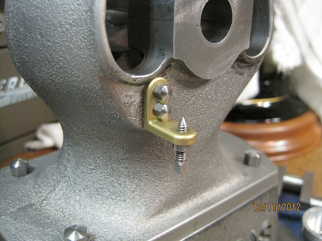
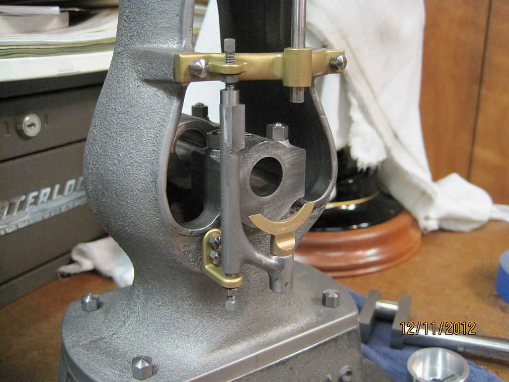
Pacific Vapor Engine from Morrison & Marvin Castings

Home Model Engine Machinist Forum

Help Support Home Model Engine Machinist Forum:

This site may earn a commission from merchant affiliate links, including eBay, Amazon, and others.
Hi Dave,
I really appreciate you taking so much time to show all of the steps in detail and explaining why you do things the way you do. Frankly I never realized how much attention to detail went into making the really beautiful engines.

th_wav

Pat
 
Thanks Pat

I’m doing my best to show how I go about things (right or wrong) and maybe someone can find something useful in all this. A plus for me is knowing that there are a bunch of guys checking for updates on my progress which tends to keep me somewhat motivated to keep working and posting progress updates.

ValveChest_025.jpg

Here are some shots of the mostly completed valve chest doing a trial fit on the cylinder.

ValveChest_026.jpg


ValveChest_027.jpg

This is the D shaped port that got me into trouble on the first go around. On the inlet side the port is on the top of the hole.

Thanks for checking in,
Dave
 
Hi everyone

I decided to continue on with the exhaust valve and related parts; I would like to try to finish this assembly before I move on to the piston, rod, and head.

My plan thus far is to deviate from the plans somewhat; I’m working to keep everything proper as far as the prototype goes. I decided not to use a couple of iron castings that came with the kit; the first one is the top support; this part guides the bottom end of the valve and also serves as a pivot for the top end of the swing arm. The reason is, first I like the look of the brass parts on the original engine; and second I don’t plan (at this time) to use the governor and I didn’t want to hack the governor latch mount off of it incase I change my mind later.

I modeled the top support in Alibre and carved it out on my CNC here at home. It is only a 2 axis so there was a lot of hand work involved.

UpperBracket_002.jpg

Here is the basic profile being cut from brass bar stock.

UpperBracket_003.jpg

The boss for the swing arm pivot is machined as it is centered in the support but not as thick.

UpperBracket_004.jpg

After the top side was machined the part was turned over and the bulk of the excess material removed from one end (notice the valve guide was reamed in the previous step).
Using the valve guide as the datum the bottom side of the pivot boss is machined.

UpperBracket_005.jpg

The rest of the excess material is removed in the band saw.

UpperBracket_006.jpg

After the support is brought to proper thickness the excess junk will be cut away.

I got carried away and didn’t take very many pictures of this process but after the machine work was completed quite a bit of time was spent with files and sandpaper getting an acceptable shape.

UpperBracket_007.jpg

I also got carried away and neglected to leave enough material for the bosses on the top and bottom of the valve guide; those were turned up and silver soldered in place.

Never the less I’m pleased how the support came out and fits the engine.

Thanks for checking in.
Dave
 
Wow Dave. That support really looks the part.

Vince
 
Hi Everyone

Continuing on with the exhaust valve and related parts the body casting needed some more machine work to fit the upper and lower swing arm supports. I altered the shape of the bottom support bracket from the print just a little; all the brackets I have seen pictures of are a little different shape and style from one to the other. I think the horsepower of the engine and possibly age determined the style of the support. I chose to model the simple right angle support with its mounting holes in line above each other.

ValveChest_019.jpg

Here the body casting along with the cylinder is set up in the mill and dialed in using the crank bearing for the datum. Every thing is based off of the center line of the engine.

ValveChest_020.jpg

The upper support mounting pads are machined to the final height; this is based on the valve chest mounting boss. I set my valve chest and upper support on the surface plate and measured the valve stem centerline. As it turns out on my engine they are in the same plane; so this is what I cut the pads to.

I will remove .01” form the valve chest later to accommodate the copper valve chest gasket thickness.

ValveChest_021.jpg

The pads are spotted, drilled, and tapped for the upper support.

ValveChest_023.jpg

The exhaust port is drilled into the cylinder.

ValveChest_024.jpg

Finished!

UpperBracket_008.jpg

Here is a mock-up shot with a dummy valve stem and temporary hardware.


Thanks for checking in.
Dave
 
Hi Vince

I forgot to say thanks for your comments; this project has been a blast so far and I appreciate you sticking it out.

Best regards,
Dave
 
Hi Everyone

I’m still working on exhaust valve related stuff; here are a group of pictures showing the machining of the swing arm. The swing arm holds the crossover cam follower shoe and the valve lifter. It is suspended between the upper and lower supports and pivots on setscrews with a 60° point.

I figured that the easiest way to hang onto this casting would be to make a fixture that allowed all machining operations to be done in one set up.

SwingArm_002.jpg

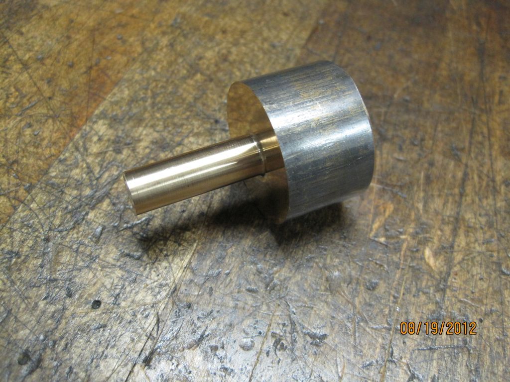
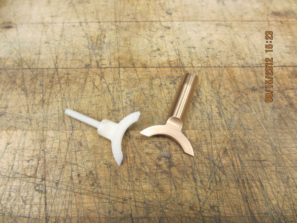
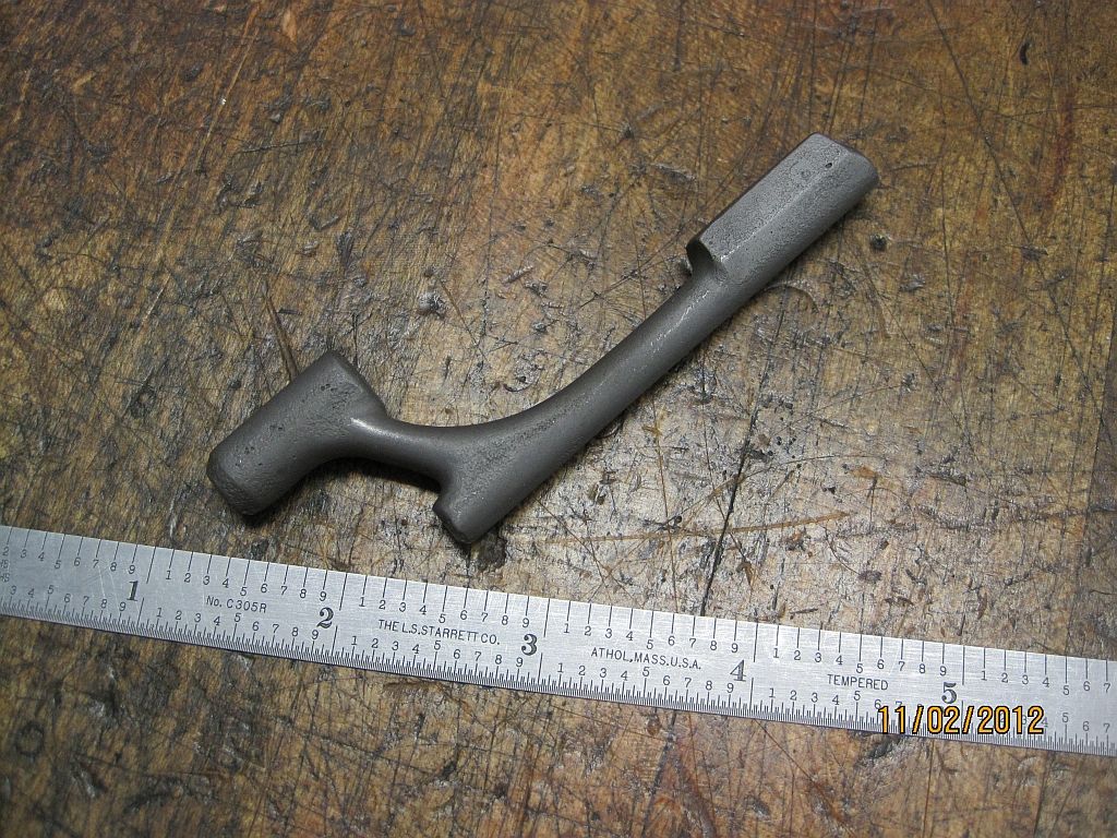
Here is the raw casting for the swing arm.

SwingArm_001.jpg

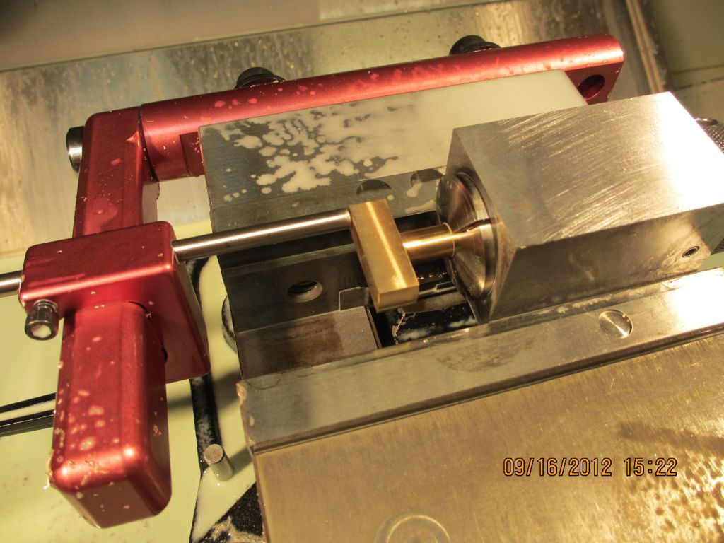
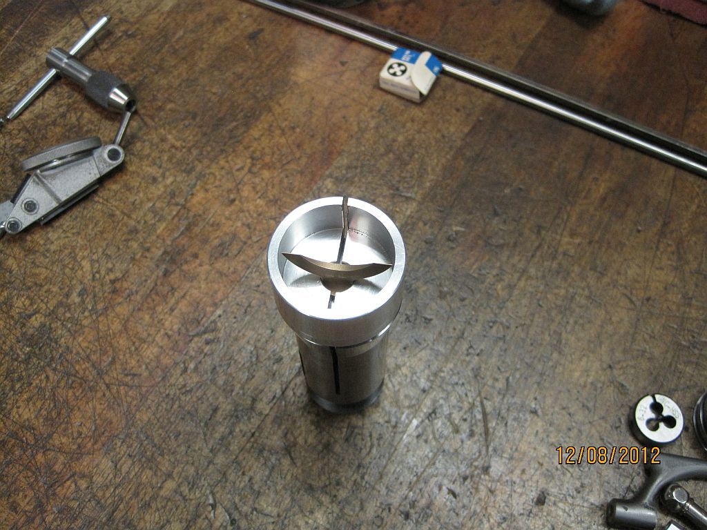
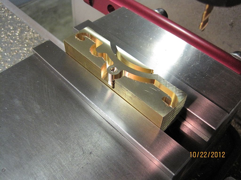
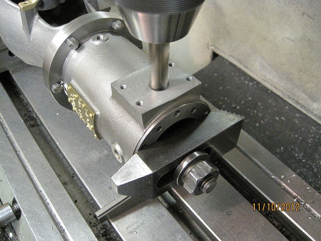
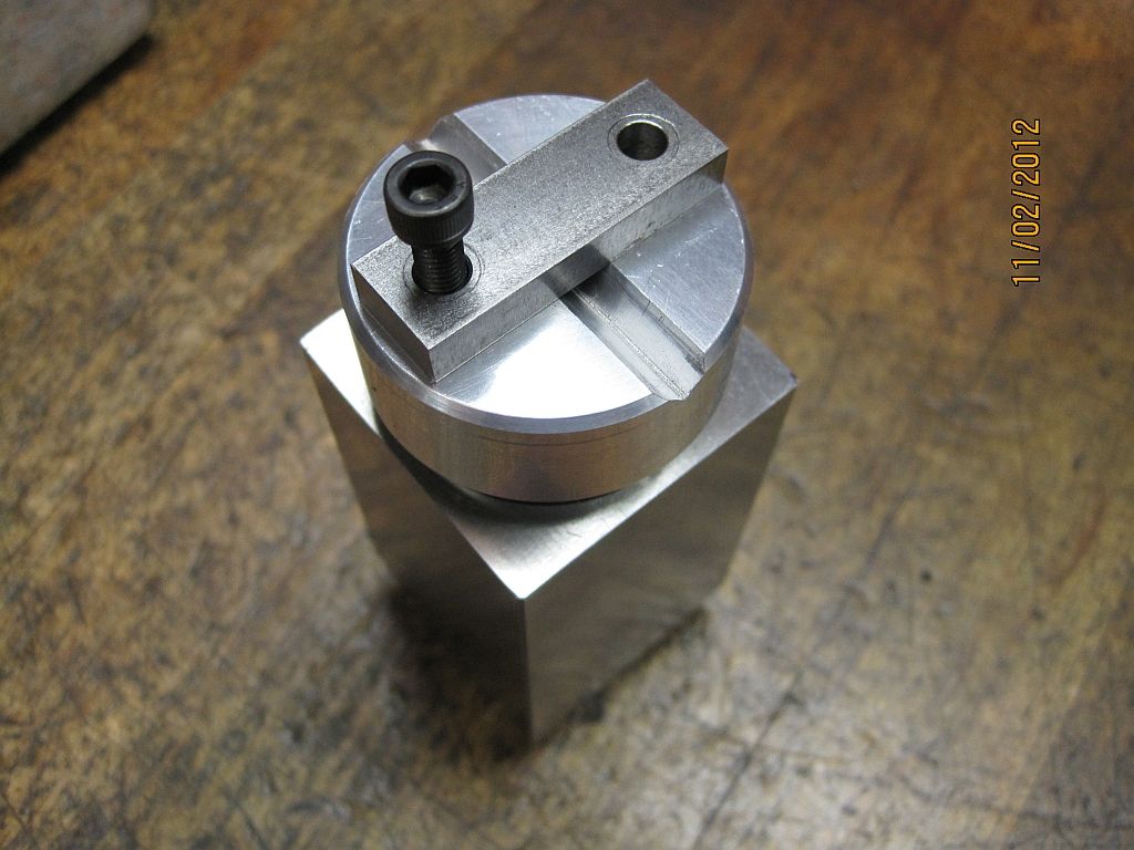
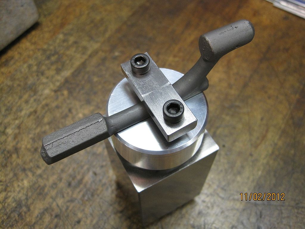
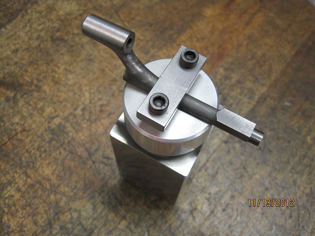
The fixture is a button V block and strap clamp indexed in a square collet block.

SwingArm_003.jpg

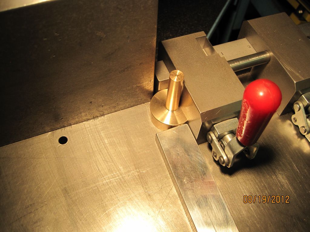
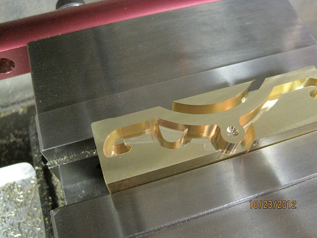
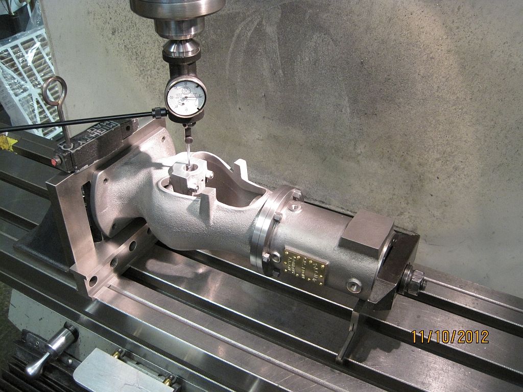
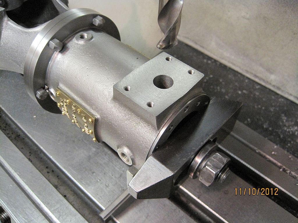
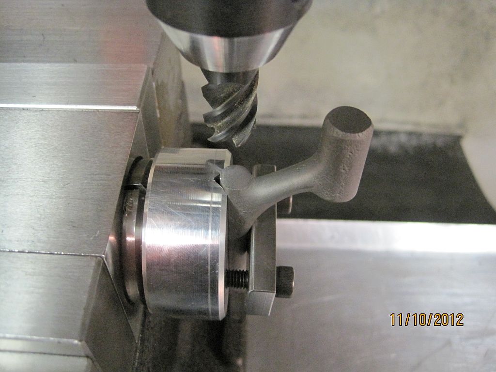
Here is the swing arm casting mounted in the fixture. The fixture was set on the surface plate and the follower shoe pivot housing was indicated to be in the same plane as the center line of the V. this was accomplished by flipping the block over and adjusting the position until the same indicator reading was obtained both ways.

SwingArm_004.jpg

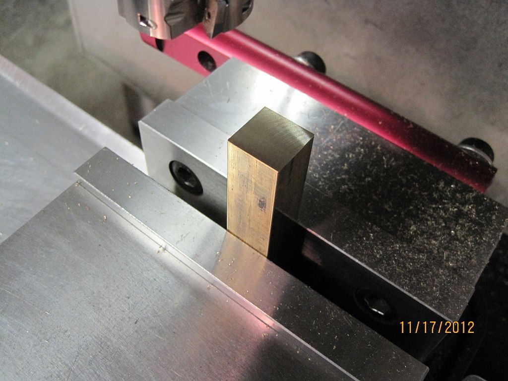
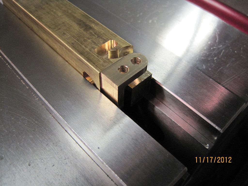
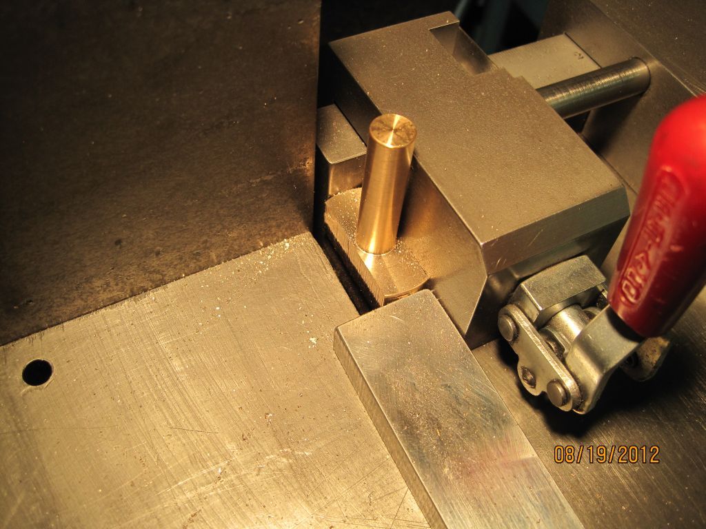
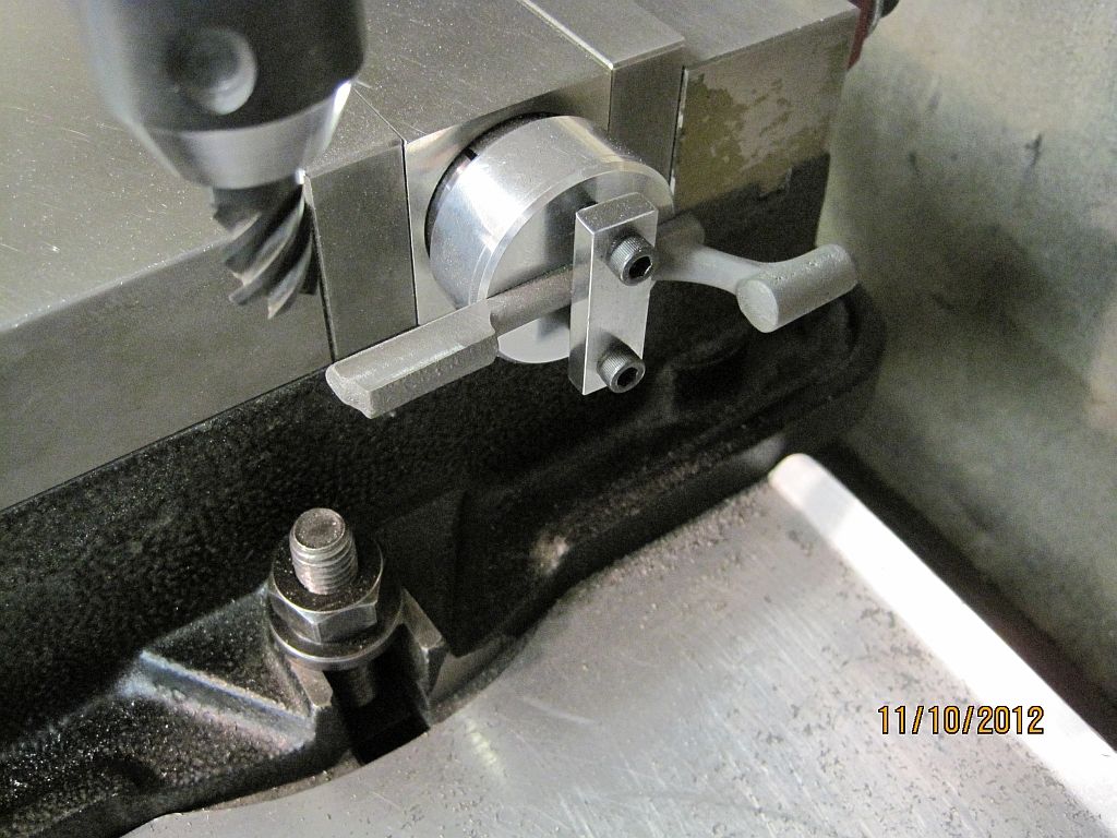
The sides of the valve lifter mounting surface are brought to the proper thickness.

SwingArm_005.jpg

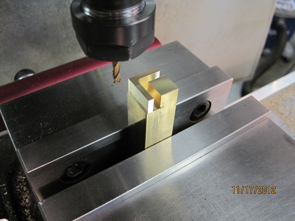
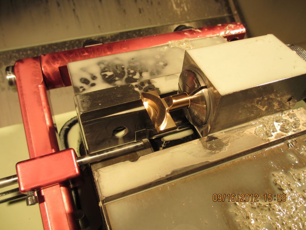
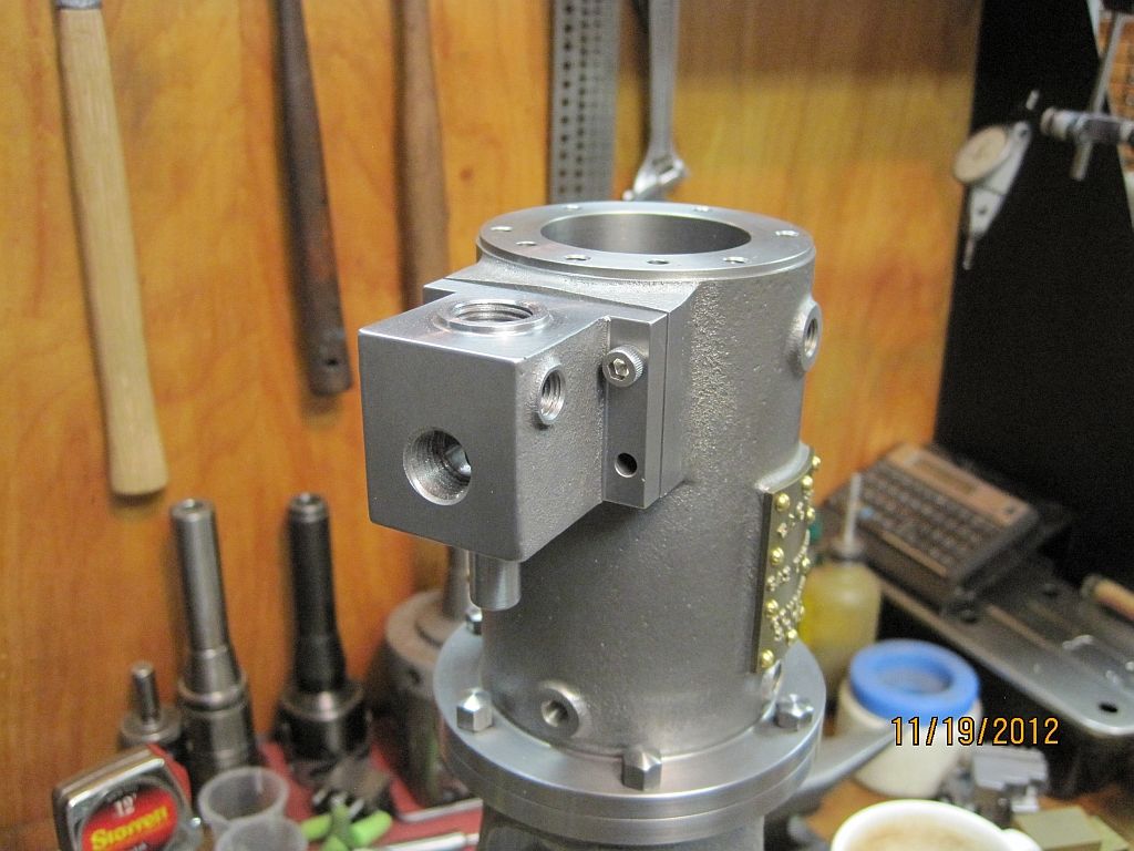
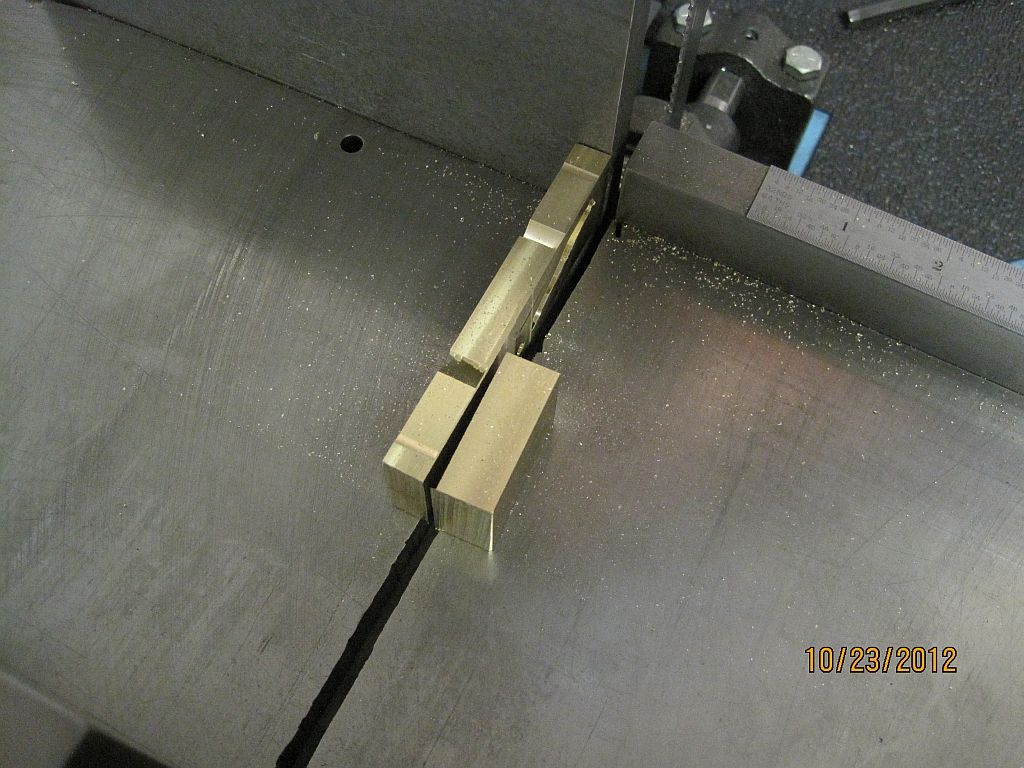
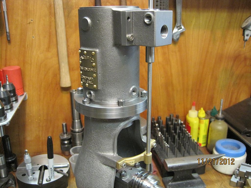
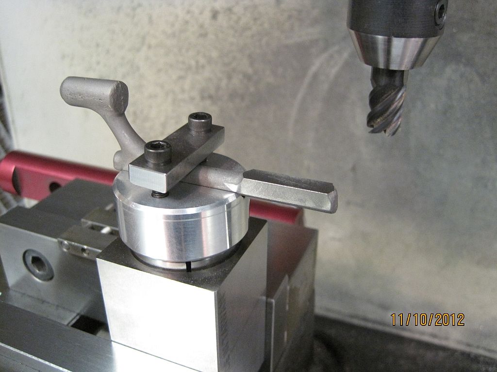
Standing the block vertical the 3rd face of the valve lifter surface is machined.

SwingArm_006.jpg

Also at this time the length of the follower shoe housing is machined as well as the top end of the arm. This length is measured from the top of the follower shoe housing.

SwingArm_007.jpg

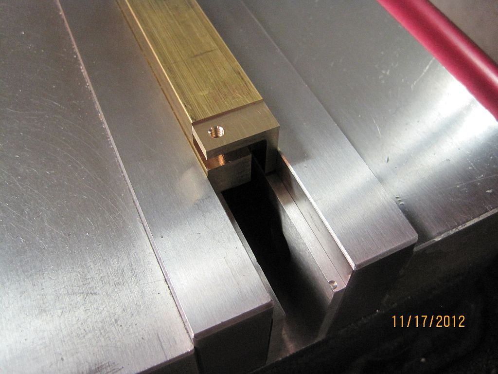
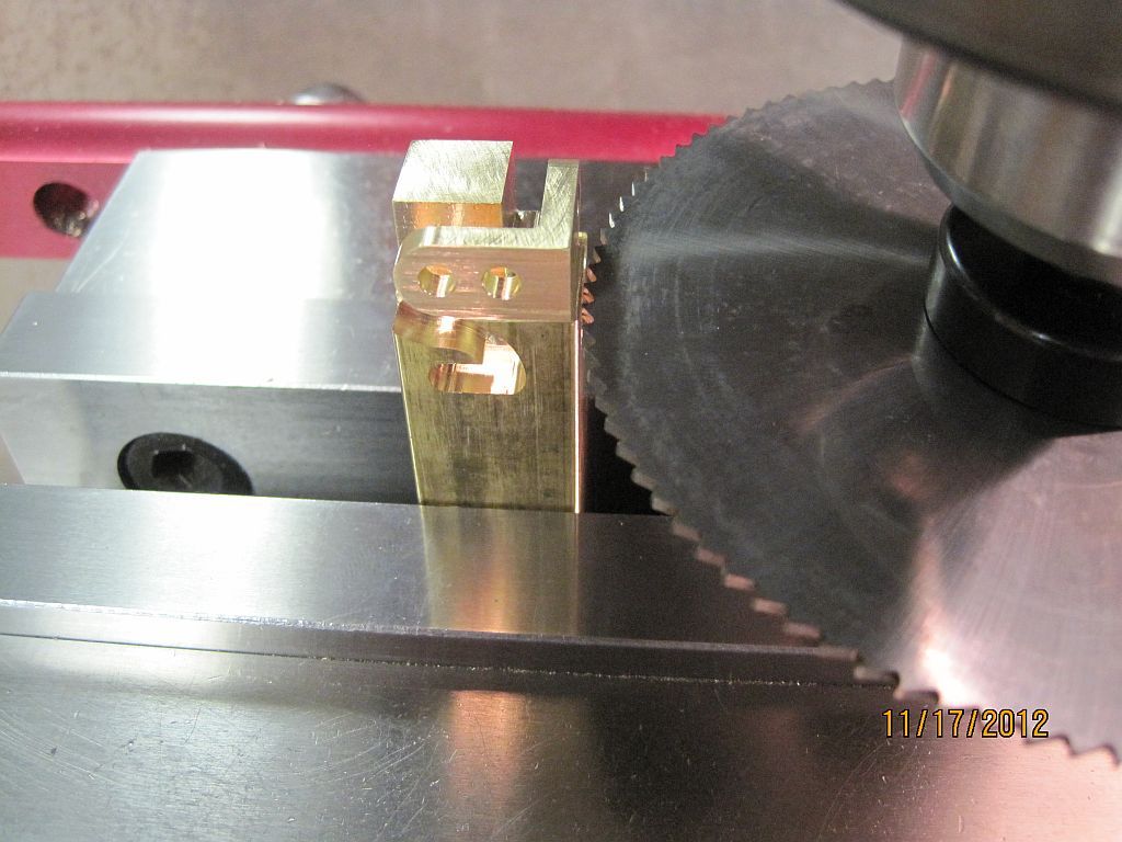
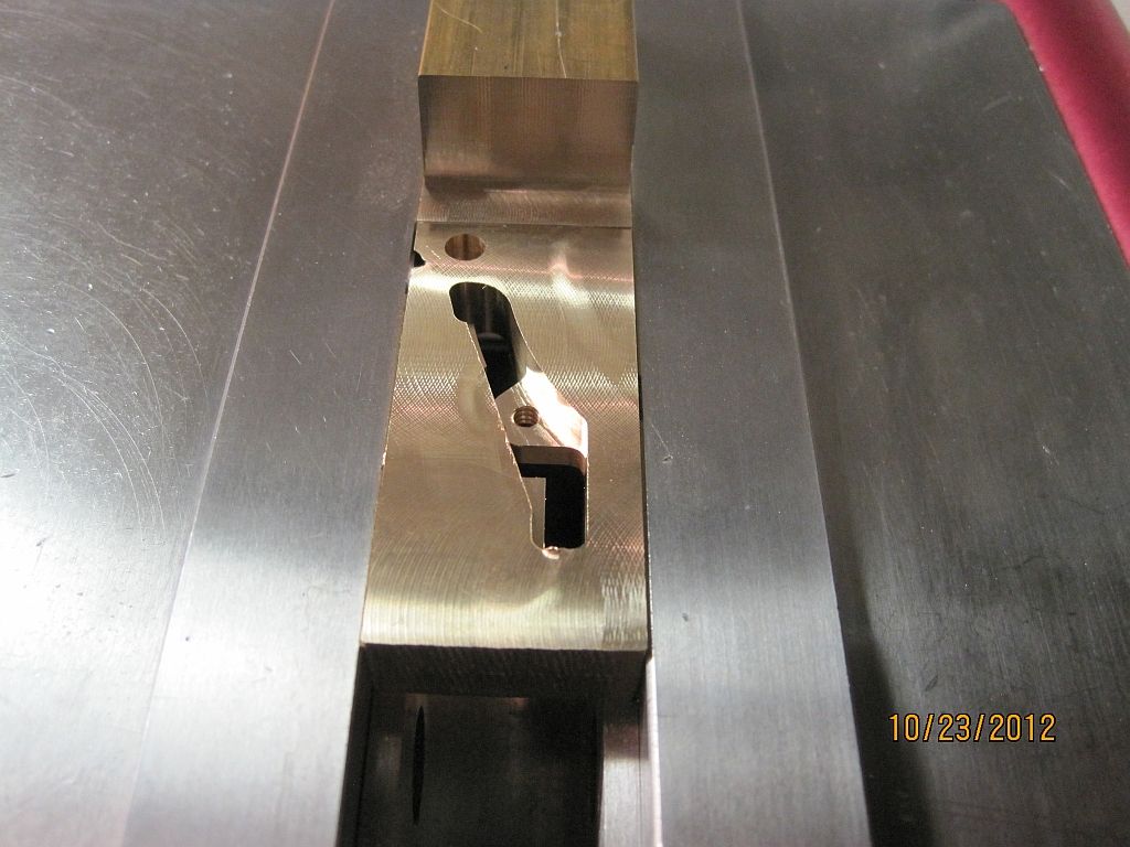
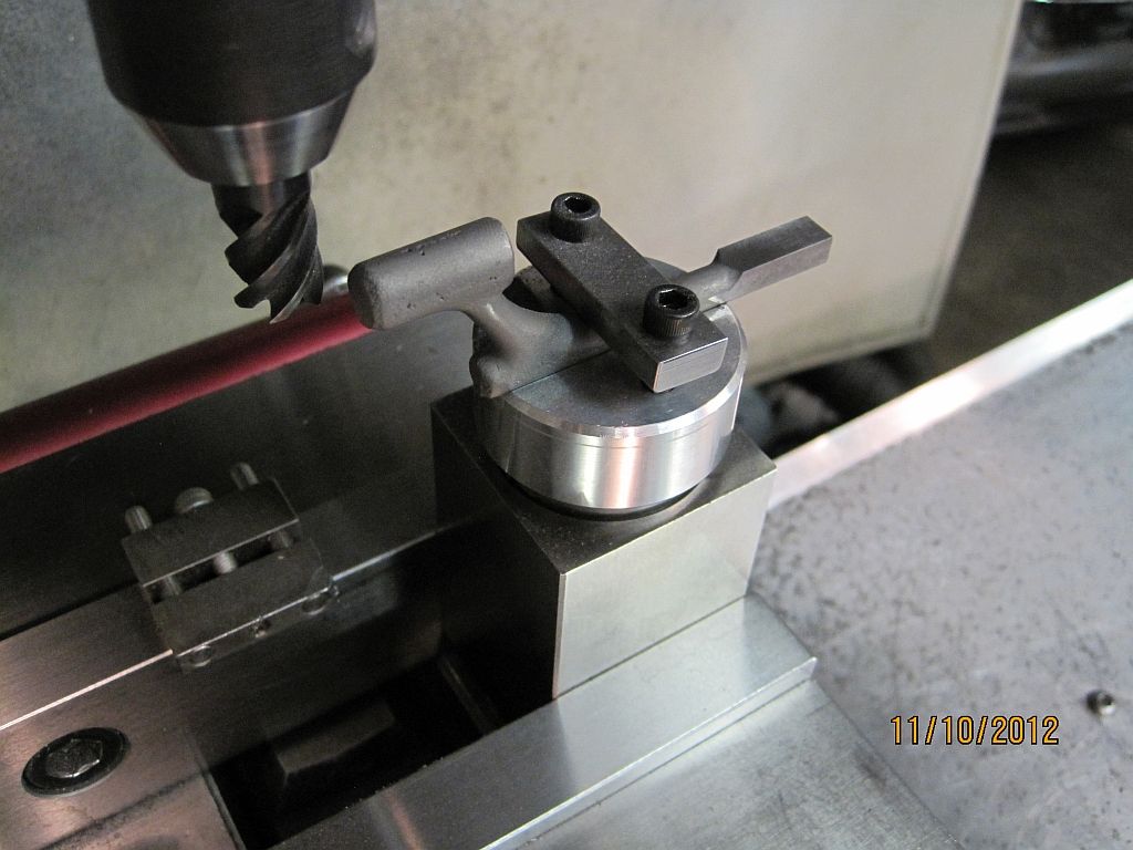
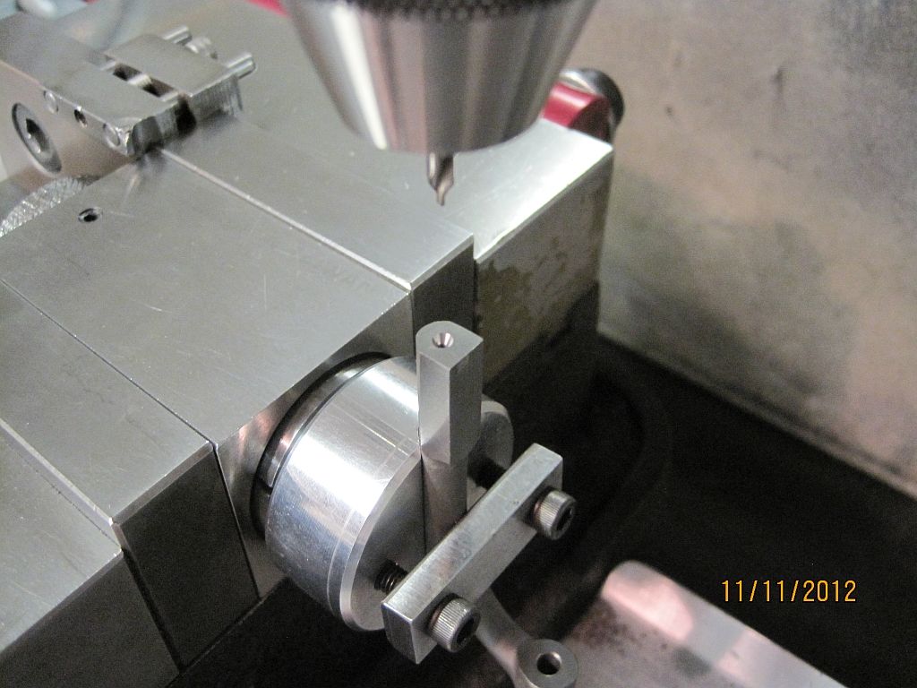
Laying the block down with the swing arm upside down; the bottom pivot area is machined flat.

SwingArm_008.jpg

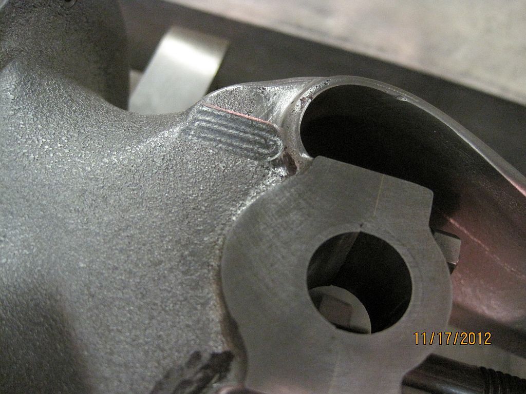
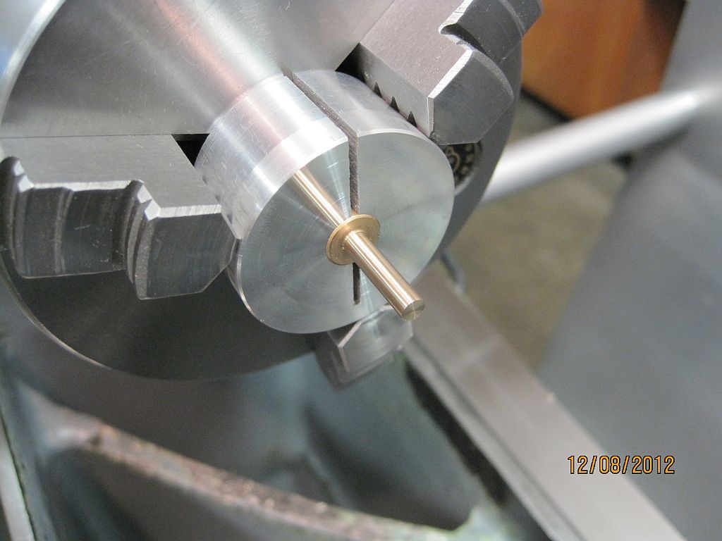
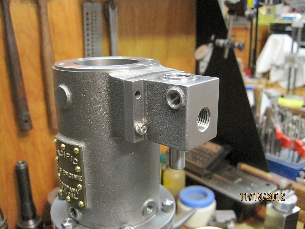
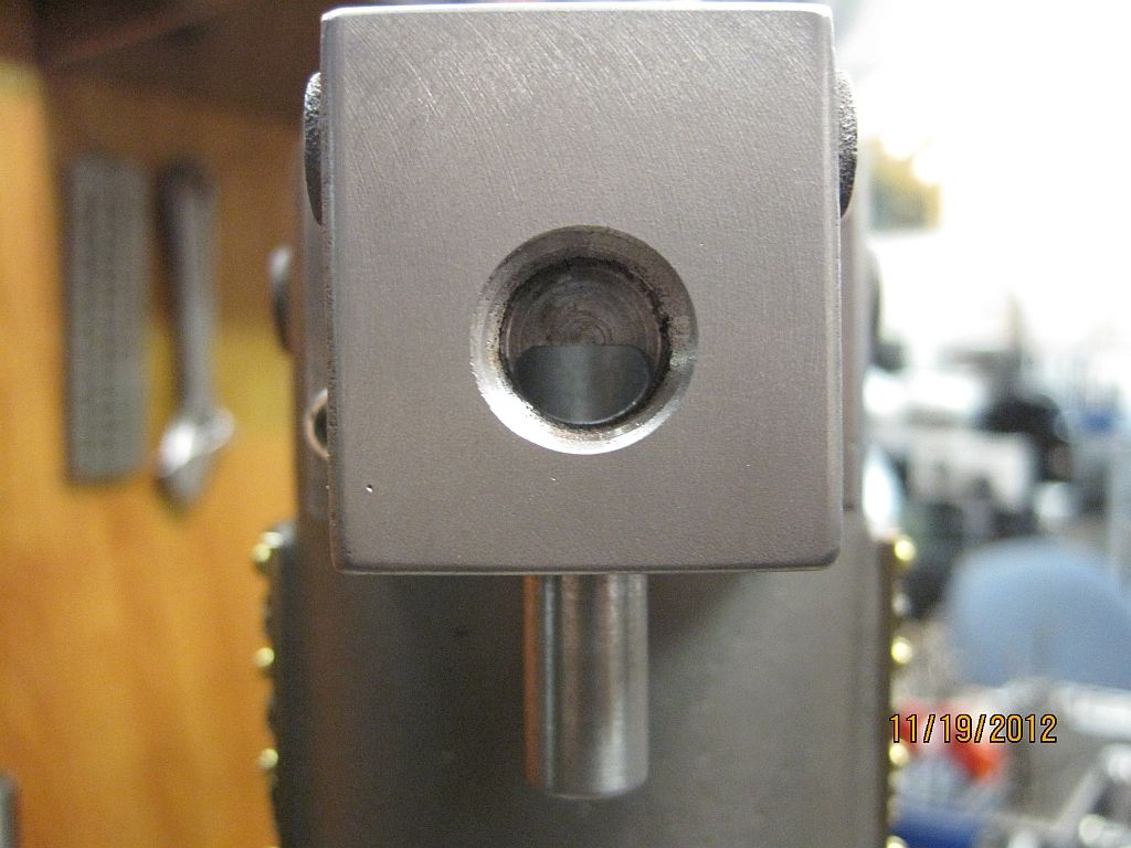
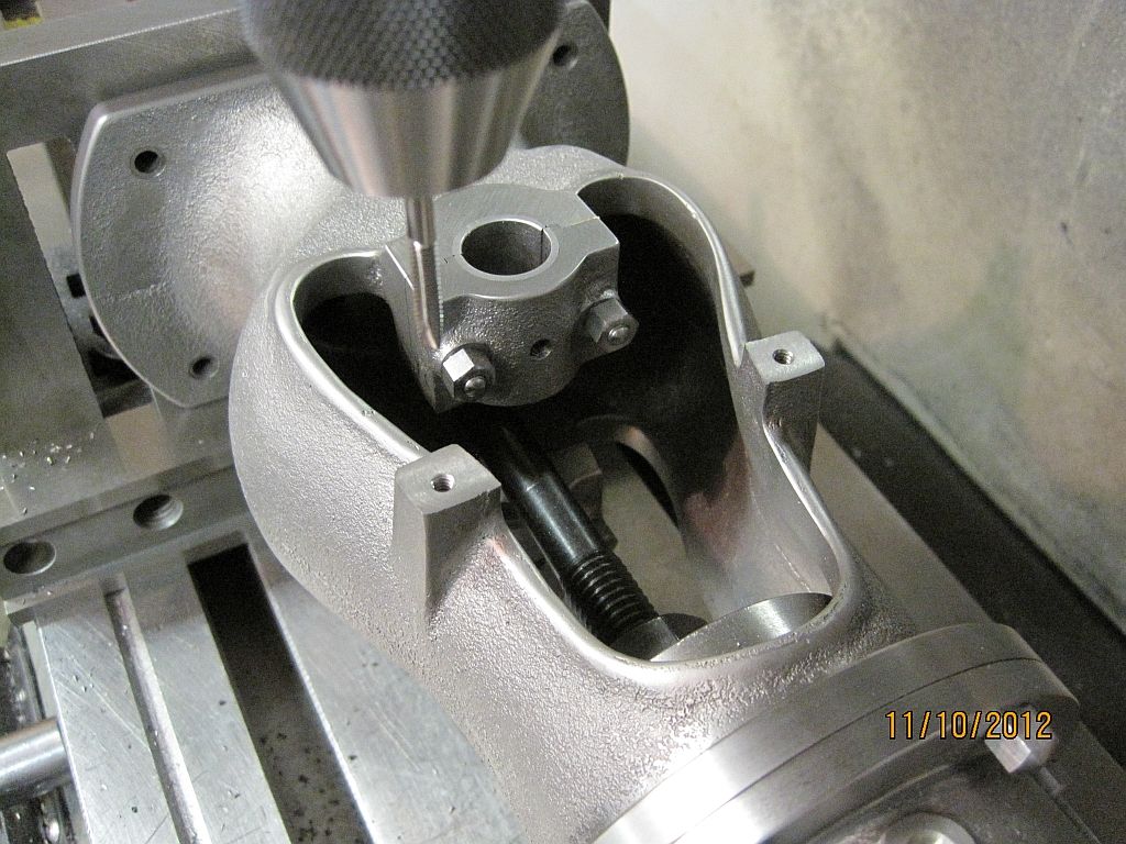
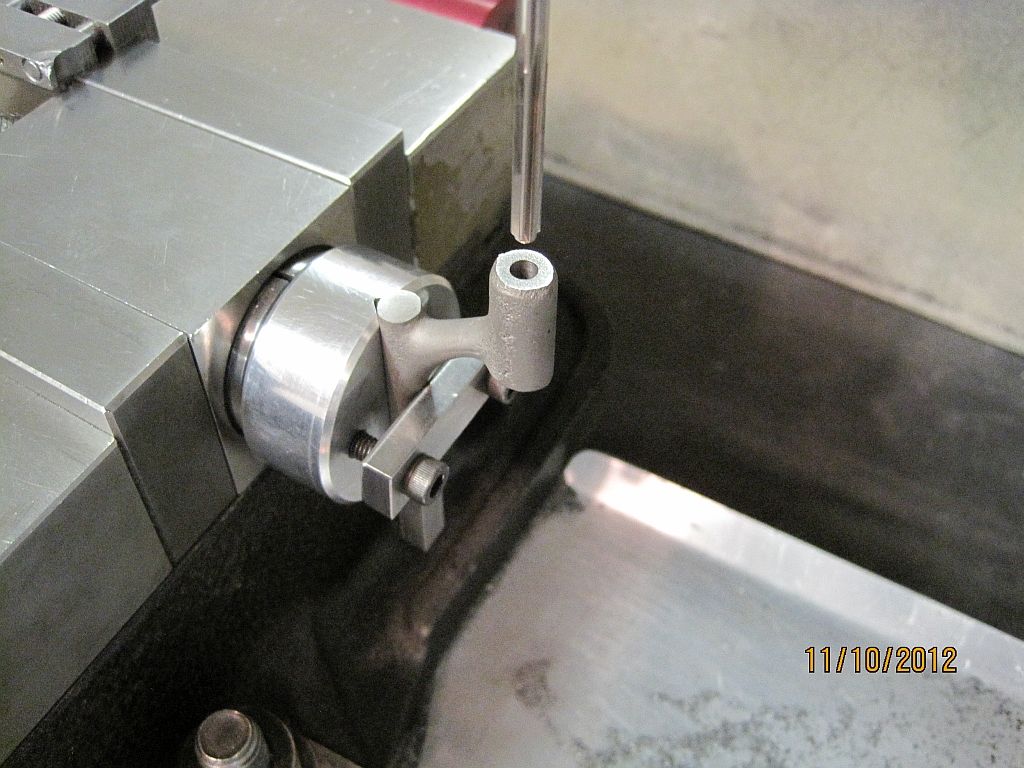
The follower shoe housing is centered up, spotted, drilled and reamed.

SwingArm_009.jpg

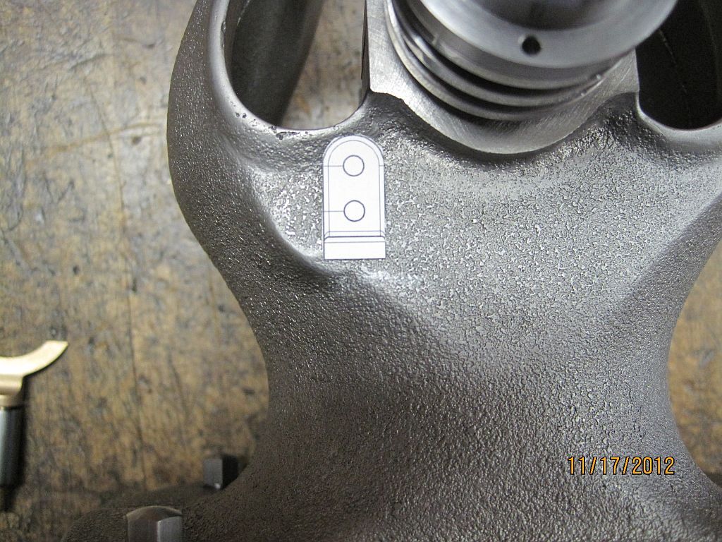
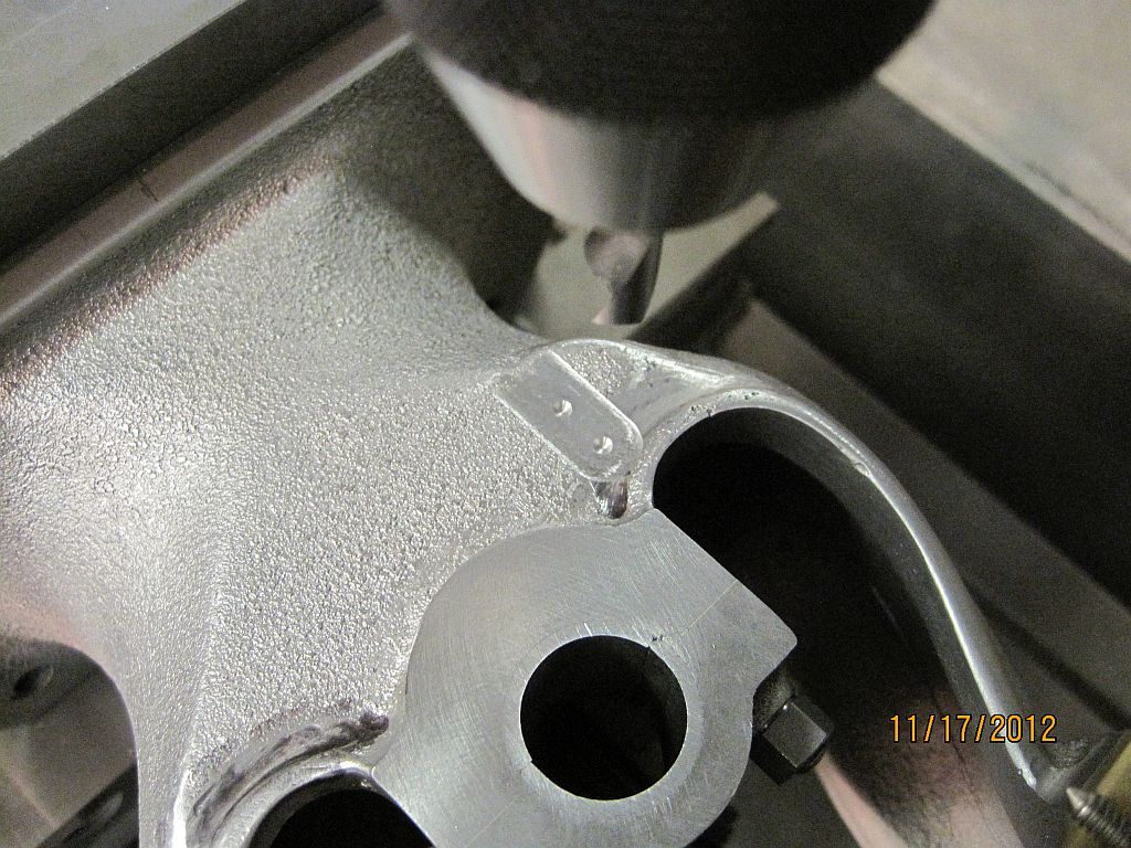
The upper and lower pivots are centered up and center drilled.

SwingArm_010.jpg

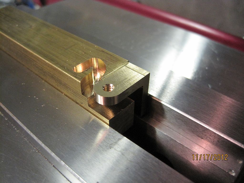
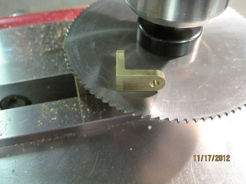
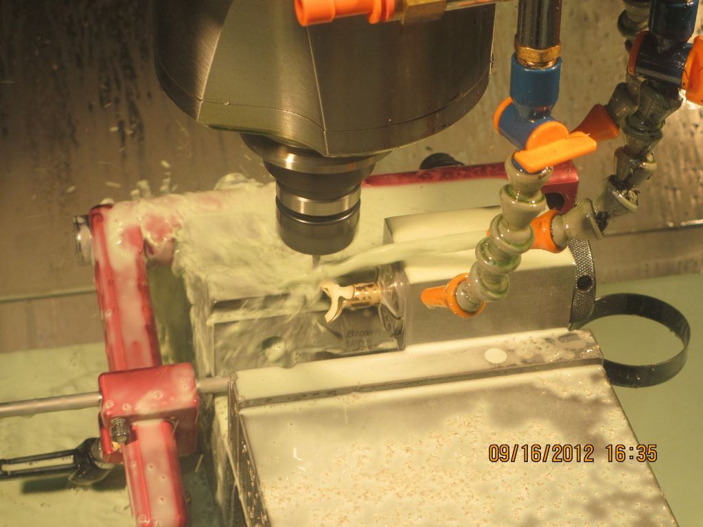
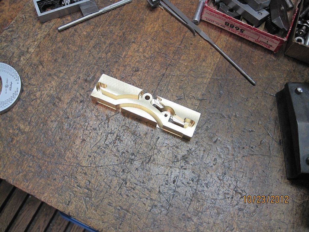
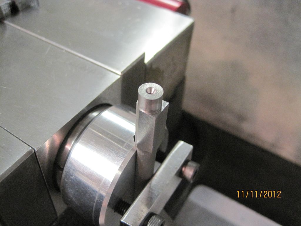
The last operation is to machine the round area on the top above where the valve lifter will mount.

SwingArm_011.jpg

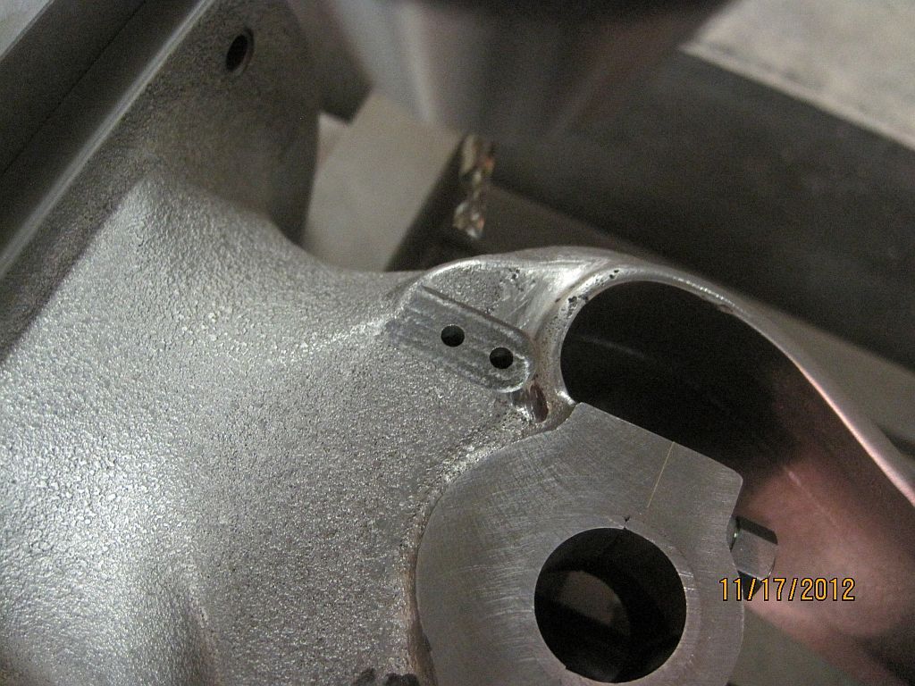
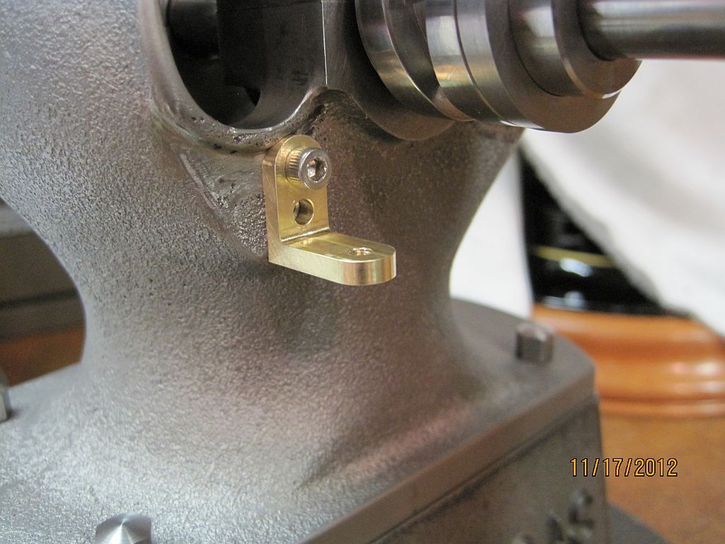
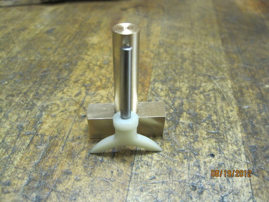
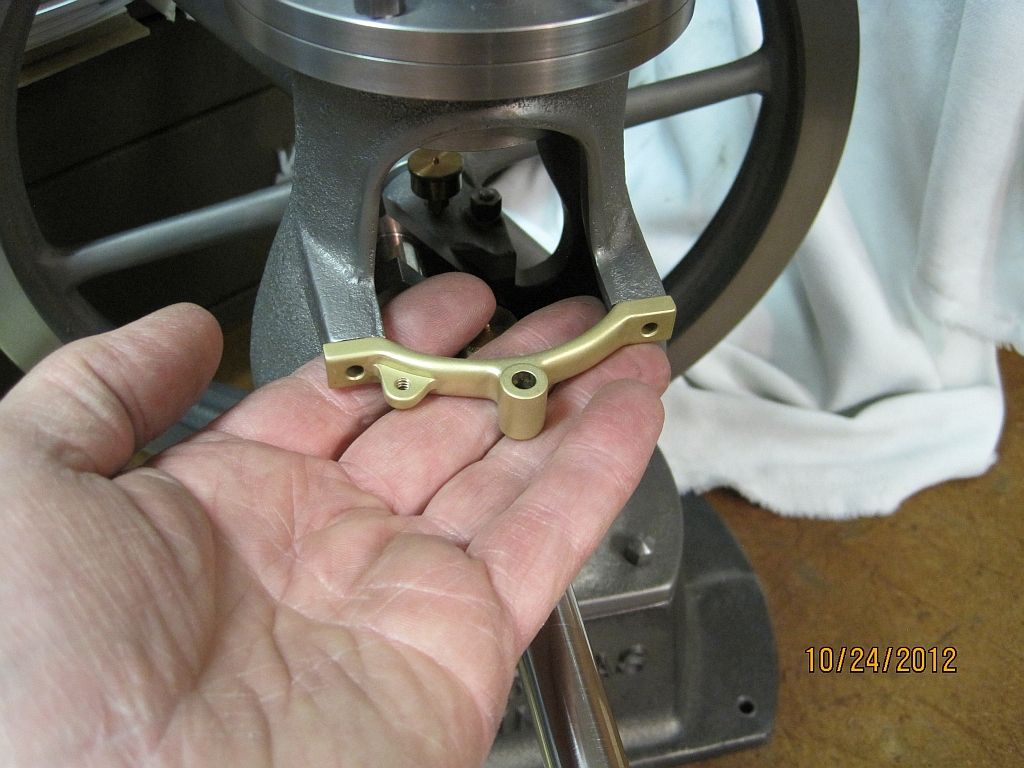
Here is the finished swing arm; the pivot hole for that valve lifter needs to be added but not until a few more parts are completed.

Thanks for checking in.
Dave
 
Dave, your fixture is a stroke of genius! That's a great idea.

Thank you for showing it to us.

Best regards,
Orrin
 
Thanks for the compliment Orrin; I appreciate it.

Dave
 
Dear Dave,

I was lucky enough to come across this train of material today. What an extraordinary resource!

The photographs are all just of a truly stunning quality, such that the contrasts between the greys is sufficient to show the components and their surfaces perfectly.

The techniques are exciting and varied (the white metal bearings story threw me back to my 16-year old self, handing the white metal crankshaft bearings on my fathers Triumph Mayflower car in about 1962).

Your descriptions are just so well written. I can't tell you how many published mechanics books have i purchased and read recently, where I have to read and re-read pages over a period of days in order to decifer meaning.

So here in these pages you have woven a perfectly clear and exciting, engaging story.

Not only are you a master at your chosen craft, you are a master at the craft of taking others along your journey too.

Please turn this one into a book! The material is already there.

Martin Thompson
 
I just caught up with your progress Dave, and I am as impressed as ever. Very nicely done, and a very enjoyable read. Thm:
 
Martin

Wow thank you for the very kind and generous words; this whole project has been an interesting journey for me in more ways than one.

Writing is not one of my strong points although I did do some technical writing in my previous job (Equipment Maintenance Technician); I struggle to put my thoughts down on paper (so to speak) but do the best I can.

As I have said before this build article is a way to help keep me focused and moving forward; which isn't always an easy task.

Thanks again,
It really makes it all worthwhile for to me to know that my fellow model engine builders are following along and enjoying the updates.

Dave
 
Hi Brian

Thanks for checking in; I appreciate your kind words and that you are still following along with my build.

Dave
 
Dave,

I'm sure that you remember that Dickens wrote his books as a series of weekly instalments that his avid readers would be waiting for. Your own writing is very clear and cogent, despite your use of techniques I have never seen before. That combination of really excellent pictures and clear text is just what we are looking for. Please re-set your opinion of your efforts here, your documentation abilty certainly equals your delightfully impressive machining skills.

I can't wait for more instalments.

Martin
 
Well; Web Shots killed all my earlier links and removed my photos as promiced when they switched over to Smile. So now I have the tedious task to restore all the pictures from Photo Bucket:mad:. I guess I will attempt to do a few at a time until they are all done.

Dave
 
Hi Everyone

Well I have been struggling to get an update posted; I have some old work and some new work to post and it is starting to get confusing to me what to do next. So if some of the dates and order of pictures seem a little strange that is why.

Last time I had machined the upper swing arm bracket and swingarm so now we will move the bottom bracket and the cross over cam follower shoe. Eventually it will all come together and make since (hopefully).

I’m also still trying to restore my missing photos from my earlier posts. I still have all the pictures but need to be uploaded to PhotoBucket and the links fixed.

BottomBracket_001.jpg

As I think that I had said before I had also changed the design of the bottom bracket slightly from the blue prints. It was modeled in Alibre and printed in full scale so the position and fit could be checked.


BottomBracket_002.jpg

Once I was happy; the body casting was cleaned up to give the bracket a nice flat place to sit.


BottomBracket_003.jpg

Then the mounting holes spotted.


BottomBracket_004.jpg

Drilled and tapped.


BottomBracket_005.jpg

Brass stock for the bracket is faced off.


BottomBracket_006.jpg

Then the profile machined.


BottomBracket_007.jpg

After laying the stock and locating the datum the pivot bolt hole is drilled and tapped.


BottomBracket_008.jpg

Then the end is rounded over.


BottomBracket_009.jpg

Flipped the other direction the mounting holes are drilled and the end rounded over.


BottomBracket_010.jpg

Standing the stock back up in the vise the bracket is sawn from the stock.


BottomBracket_011.jpg

Almost done!


BottomBracket_012.jpg

Checking the fit.


BottomBracket_013.jpg

Here is the bracket after some hand work and a trip through the blast cabinet; also the proper hardware has been machined and installed.

Next time the bronze follower shoe.


Thanks for checking in,

Dave
 
Last edited:
Hi Everyone

Now on to the follower shoe; this was my first trial part I had made this summer. I made a couple extras that I can finish up if needed.

The original shoe was a bronze casting so I decided to make mine one piece instead of a silver soldered assembly.

Shoe_001.jpg

Here the blank has been turned from 660 bronze stock.

Shoe_002.jpg

Then the excess was cut off in the band saw.

Shoe_004.jpg

And the other side.

Shoe_005.jpg

The blank was machined to the proper thickness; here it is standing behind a rapid proto-type part that I made at work.

Shoe_006.jpg

Here the blank is set up in the mill to machine the first side; I did this at work on my CNC but could easily be made on a manual machine.

Shoe_007.jpg

The first side has been surfaced with a small carbide ball end mill.

Shoe_009.jpg

Working on the second side

Shoe_010.jpg

Here is the part off of the mill next to one of the prototype parts.

Shoe_011.jpg

Because the shank was left oversize for rigidity a split collet was made to hold the cam so the shank could be turned down.

Shoe_012.jpg

Here is the collet in use.

Shoe_013.jpg

And finally a group shot with all the parts and the proper hardware machined and installed.

Thanks for checking in.
Dave
 
Wow Dave.

How I wish I had CNC capability. Someday, maybe.

Vince
 
Nice work on the governor bracketry, Dave. I'll have to remember the tip of printing out layouts and using them to check fits. It is going to be a sweet machine when you finish.
 
Thanks Myrickman I appreciate it.

Vince, I really enjoy the whole process CAD/ CAM and running the machine. I converted my mill over 15 years ago and taught myself how to run it (the CNCpart). It has been a wonderful journey.

I had a good background in manual machining and this was a logical progression for me I have never been sorry for heading down this path. It also worked out favorably for me when an opening became available in the shop where I now work. Had It not been for my CNC experience (although somewhat limited) Iwouldn’t have been considered for this position.

Dave
 
Back
Top