Pacific Vapor Engine from Morrison & Marvin Castings

Home Model Engine Machinist Forum

Help Support Home Model Engine Machinist Forum:

This site may earn a commission from merchant affiliate links, including eBay, Amazon, and others.
Hi Dave,
Outstanding work on your engine. As stated, your attention to detail is first rate. It looks like the M&M castings are nice and clean. That sure makes it easier to work with.
As a side note on the engraving, I wanted engraved I.D. plates made up for my engine boxes so after scouring the Yellow Pages I went to a trophy engraving shop. I explained what I wanted and he said they didn't do actual cutter engraving any longer, at least not for what I wanted. His alternative was to do some type of photo etching. It's nice but not engraved.
gbritnell
 
Hi Dave,

Glad I found this project, looks a fantastic engine... something different to the norm. The castings look good but your machining even better! I have not seen white metal bearings done before either. We have an old car that needs an engine rebuild and has white metal big ends, will have to find someone that can do it or a shell bearing that would fit. Looking at your post it's almost tempting to try it myself but it'd be an awkward shape to grip and I think you made it look far easier than it was!

Nick
 
Brock, Vince, Dave (Steamer), George, & Nick

Wow! Thanks guys for all the great support; it really means a lot to me, especially from some of our most talented members.

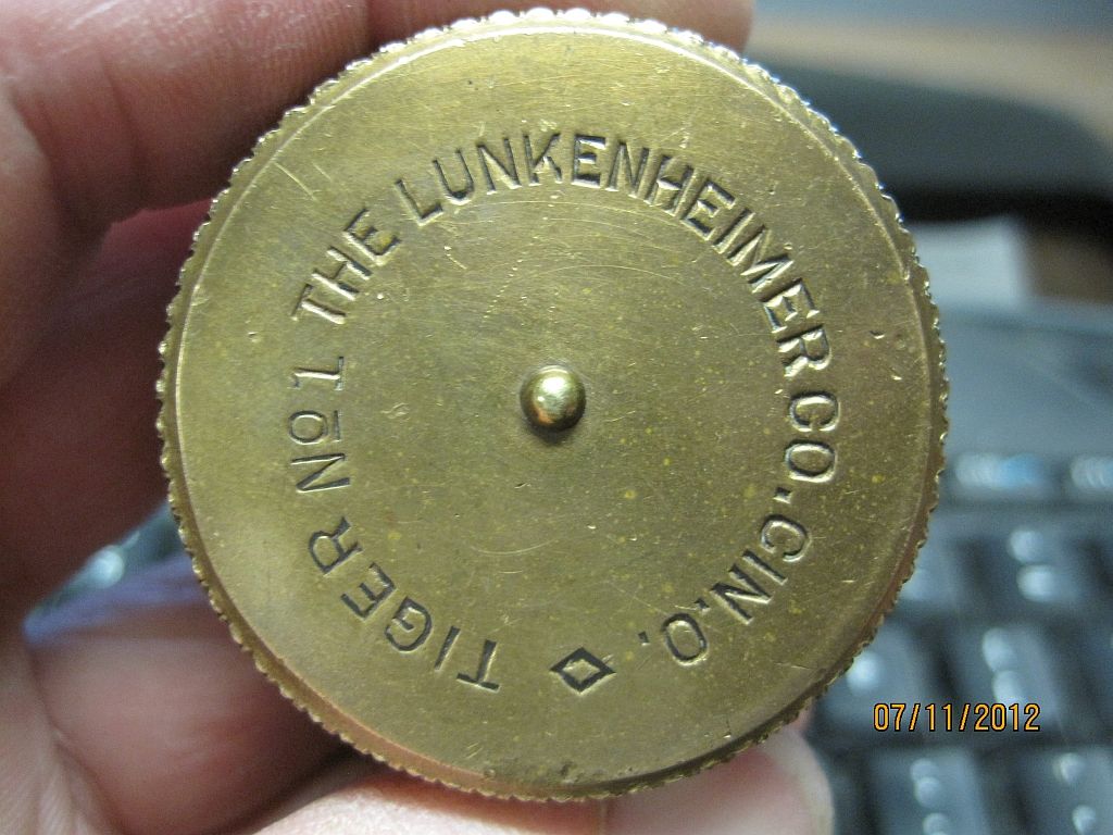
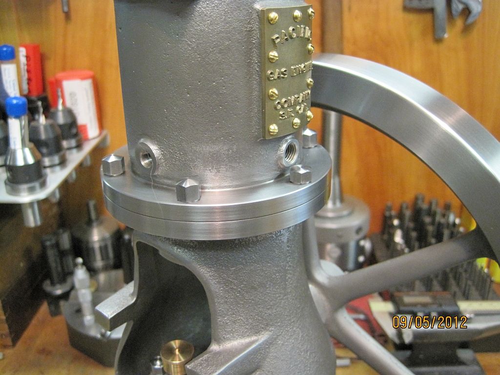
With regards to the lettering on the grease cups; here is a picture of what I am trying to do. I really want to do this myself and having access to CNC mill both at work and home it should be doable.

GreaseCup_014_zpseb588a10.jpg


What I’m trying to determine is the best type of cutter. I have some good information from an acquaintance on how to grind a cutter on the Deckel SO grinder that will work. So this may be the first try.

I have also been looking at the diamond drag engravers on eBay; they are only about $70.00 so this is also a possibility.

I will do the CAD work on the letters and most likely do the engraving on my Fadal mill at work. I will keep you guys posted on the outcome.

George I think I’m familiar with the type of photo etching you are referring to. I have also done some name plate etching for full sized engines and a couple of models using ferric chloride and a laser printed mask. This may be a possibility but I think I want to give engraving a try.

Dave; the Weiler is my pride and joy. I was able to purchase it from a local machinery dealer here in town. It came from my employer and due to some consolidation they were getting rid of a bunch of machinery and tooling; I purchased 18 or so years ago.

It went from the plant directly to my garage. It was purchased new by my employer for the tool and die shop so I’m the second owner. After moving out of the tool shop it spent some time in one of the maintenance departments where I happened to be working at the time. I replaced the cross feed screw and nuts during that time; these parts cost more than most HSM guys spend on a whole new lathe. I glad I didn’t have to by them out of my own pocket.

One strange thing is there was no follow rest or steady rest purchased with the lathe. I purchased one on eBay that would work and re-machined the base to fit the Weiler.

I have sense purchased the proper steady from a guy over on the PM web site. Also because the 3 jaw was huge 8” a few years back I purchased 3 & 6 jaw Bison chucks both in 6” size. The back plates had to be machined by me because of the funky DIN spindle nose.

It is a relatively rigid machine and will happily remove .2” from the diameter of aluminum or leaded steel stock.

Funny story; I started working in the Model Shop at work (R&D machine shop) about a year and a half ago; this is a small shop with only 5 of us. One day, one of my coworkers and I were digging through a small cabinet looking for something when we found,-------the carriage stop for my Weiler! Boy was I happy with that; it even had the matching serial number stamped on it.


Ok I will quit rambling now; But thanks again guys for all your kind words; it makes my day.


Dave
 
Last edited:
Great work Dave. That is one sexy looking engine. I had somehow lost track of this build, and spent my lunch hour catching up.

Thanks for all the detail on the babbit pour. Thanks also for pointing out how you make the nuts on my PMR#1 build log. I really like your results and plan to do something similar.
 
Hi Dave,
At work when we did 'special jobs' for retiring executives we would engrave a lot of text on brass plates. The tools we used were just the pointed engraving tools that are ground flat just past the centerline. They seemed to work just fine.
gbritnell
 

Beautiful work Dave.

It is great to see the poured babbit bearings. When I went to trade school we were taught how to blue and scrape them in. It has since been dropped from the curriculum...

Great shop too!

 
That is some very impressive work Dave. You still have my interest.

Don
 
Hi Guys

Brian, Kevin, Don,

Thanks for the kind words; I was hoping to get some work done on the Pacific this weekend but my time seems to be getting vacuumed up with other commitments.
I may get some time for myself on Sunday; we'll see.

George, I think I have the type of single lip engraving that you are describing; I purchased it to engrave a logo on some alternator brackets that I make. I wasn't very happy with it and just chocked it up to not enough spindle RPM.

With the very small depth of cut on the grease cup letters it just may work; I will have to do a test cut and see what happens.

Thanks again guys,
Dave
 
Hi Everyone,

Well it has been a long dry spell for the Pacific but I finally got a couple of days to play over the holiday weekend.

I was able to get all the 12-24 high crown bolts made; as well as some machining to the bottom of the cylinder mounting flange.

Bolts_zps5641c36d.jpg

The 5/16" hex stock was chucked in the small 3 jaw; turned, chamfered and threaded with the tail stock die holder.

Bolts_2_zps4baf7cc6.jpg

The the bolts are turned around and held in a collet; turned to length and the radius cut using a form tool.

Bolts_3_zps8a6170b0.jpg

Here are the finished bolts; the long ones will be used to hold the engine to the skids or base when the time comes.

Bolts_4_zps5ddeded8.jpg

Here are the cylinder mounting bolts installed; note there are two of them under the water ports that have to be shorter to clear the piping. This is the way the original engines were.

Bolts_5_zps13a73a41.jpg

Here is a worms eye view of the same.

BodyMods_1_zps72c5ede9.jpg

One detail still needing attention on the body casting was to thin the cylinder mounting flange. The way mine came out I needed to remove almost .1" to get it to the .281" dimension on the print.

BodyMods_2_zps1958978e.jpg


A support bar was made to support the flange end while the body was held in the 4 jaw chuck. The center was left a little loose while the flange was indicated; then tightened enough to support the body.

BodyMods_3_zps81398c18.jpg

Here you can see the rough cast uneven surface of the underside of the flange.

BodyMods_4_zps7d9829a9.jpg

And after a little machining and blending.

Hopefully my next update won't be another 2 months away but I'm afraid I won't be able to get much more done before the GEARS show at the end of the month.

Thanks for checking in.

Dave
 
Last edited:
Looking good Dave. I am very happy to see this project is still alive. I was worried we had lost it in the change over.
 
Thanks Brian,

I was lucky earlier this year to have time to work on the engine; then I got very busy both at my day job and also my home shop. I have also been doing some repairs on a Brockway Phillips hot air fan for a friend; I may post a picture of it when it is completed.

Hopefully this fall and winter I will continue to have time for the Pacific; there also has been some background work going on for the crossover cam and it's follower shoe. When I get a minute I will post a couple of pictures of that also.

Best regards,
Dave
 
Dave

It's good to see some more progress on the engine.

Vince
 
Thanks for the update Dave, I really enjoy looking at your methods and the crisp details your machining produces.
 
Hey Dave, I am really enjoying this build. I am learning a lot of techniques for doing the machining. It was good to see you at GEARS. Hope you get time to get back to this build soon.

Pat Wicker
 
Thanks Pat and also Jan from a while ago.

I have managed to get a couple of small items worked on; I need to find time to get posting again. Hopefully I will have some more time after the fall yard work is finished.
I found out that Web Shots where I have a lot of pictures and all the Pacific and MM Vise pictures will be changing over to a new site called Smile. What this means is as of Dec.31 all my links to the pictures in my build posts will not work anymore :wall:.

So along with trying to do some new updates I need to deal with this. I have a Photo bucket account and have started moving my photos over there; wow what a pain. If anyone has any suggestions I'm all ears.

The new Smile (Web shots replacement) apparently will not allow public links to your pictures and after the first month it won't be free.

Pat thanks go out to you and the team for putting together another great GEARS show.

Dave
 
Hi all,

Well here is a long coming update on my Pacific project. I have been working on the exhaust valve chest casting and some of the related timing parts. The relationship of all these parts is somewhat critical so everything works properly. I took only the minimum amount from the valve chest mating surfaces to clean the rough casting. I wanted to keep the valve (initially) as far from the center line of the engine as possible. As it turned out this worked out well; if you build one of these engines I would highly recommend proceeding with caution at this stage.

You will probably notice that some of the pictures seem out of order; this is because I stuffed the casting and had to request a new one from Roland:mad:
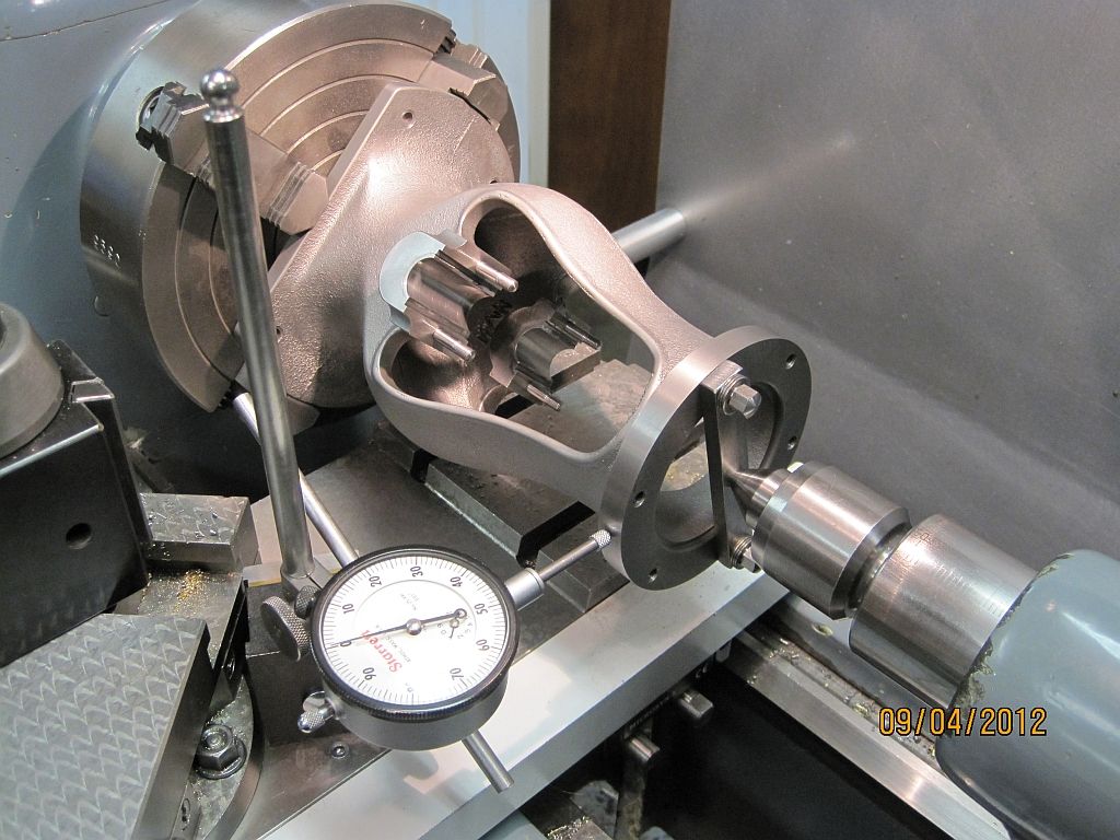
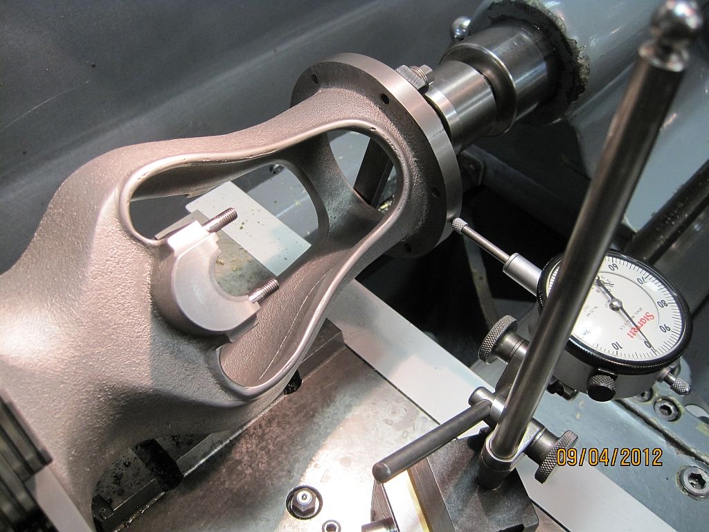
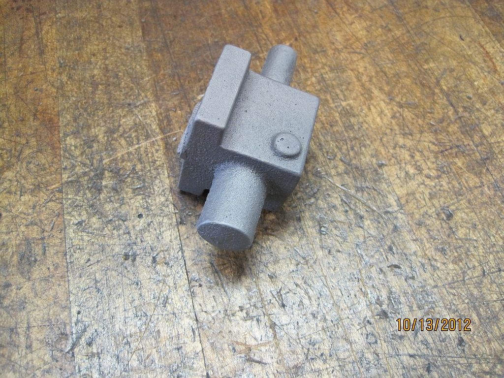
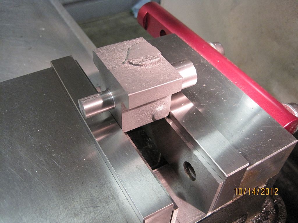
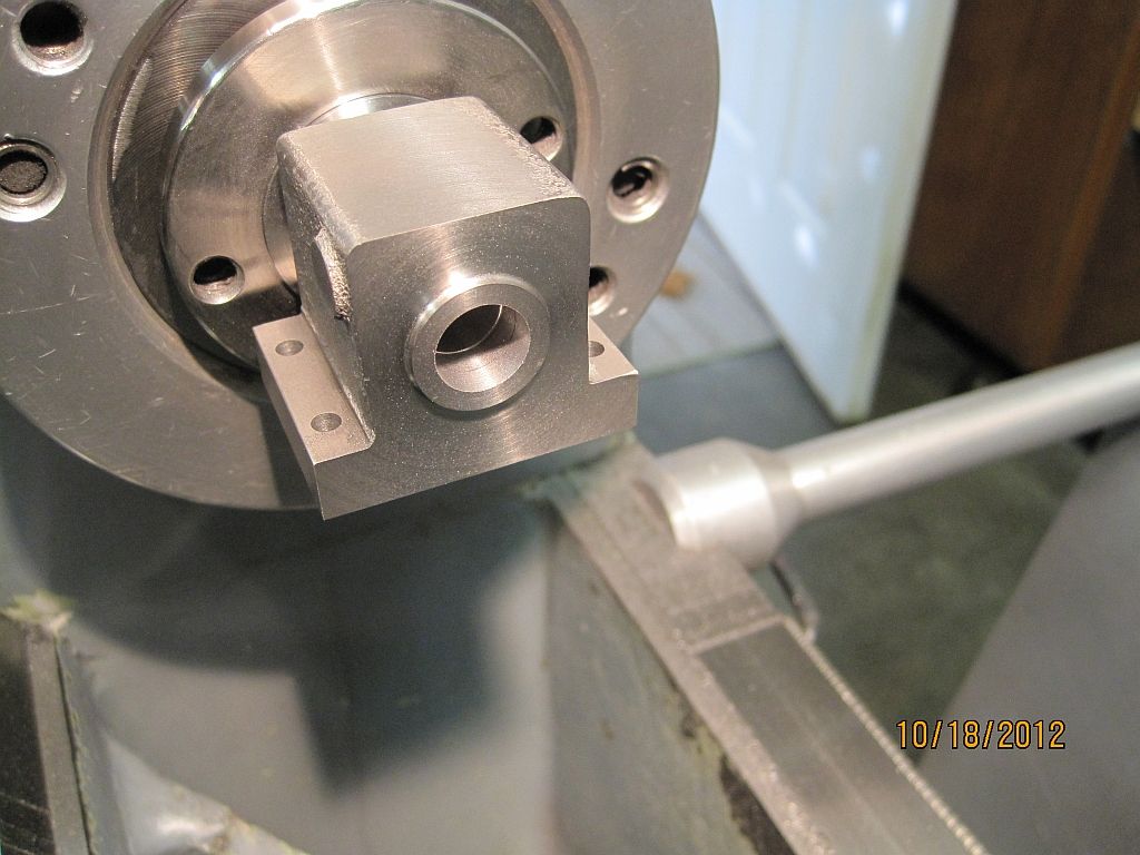
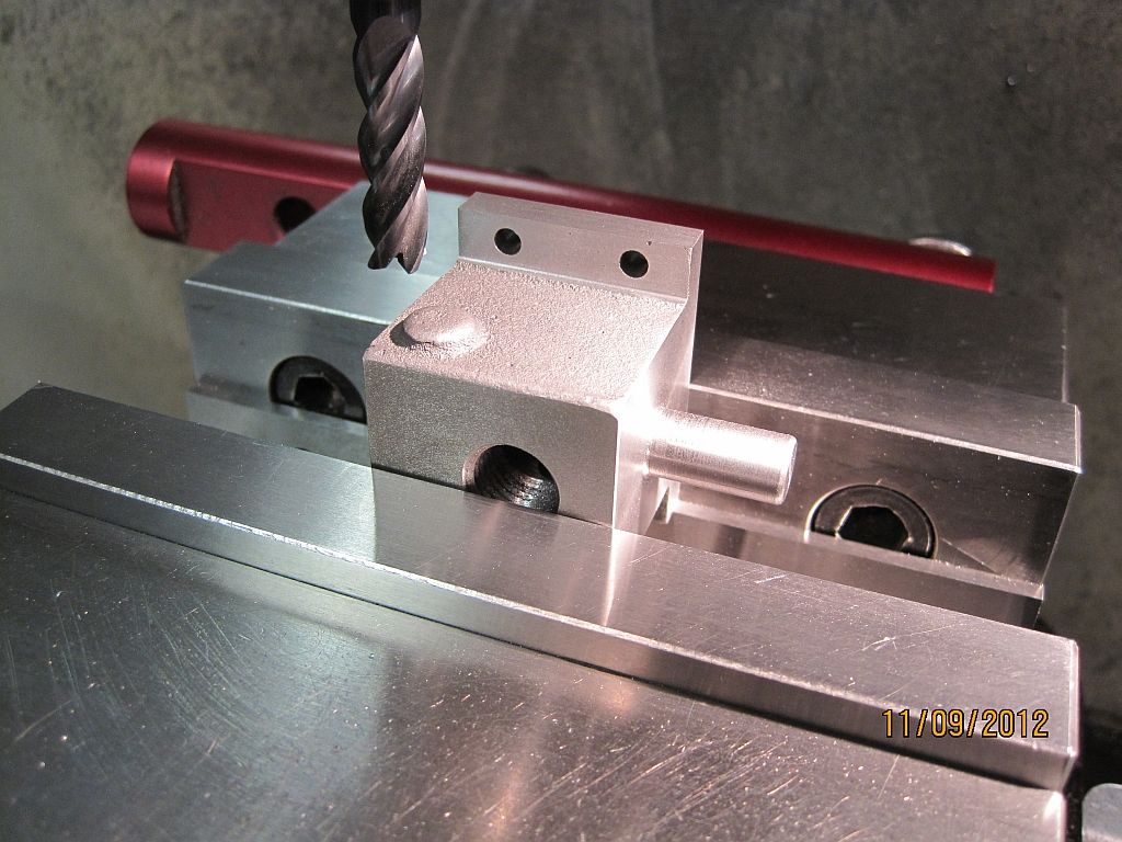
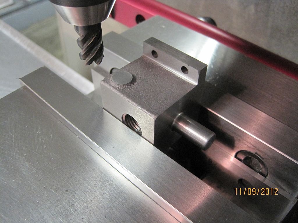
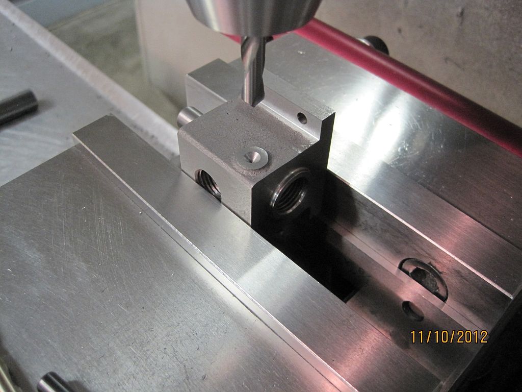
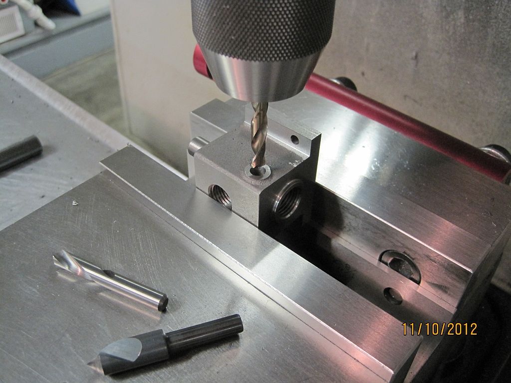
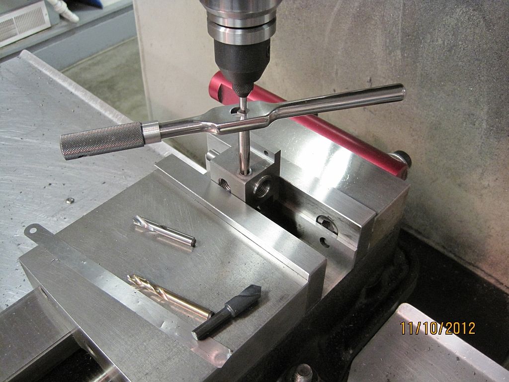
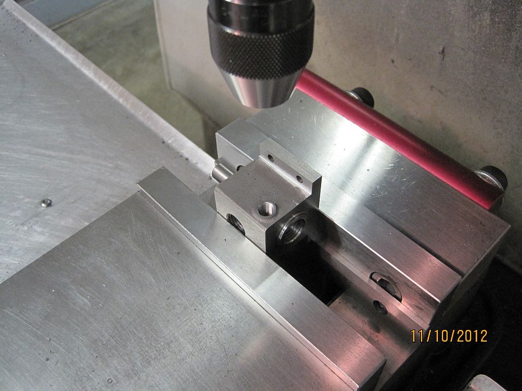
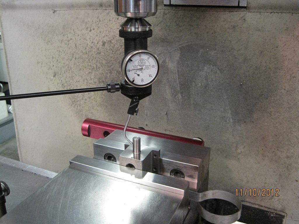
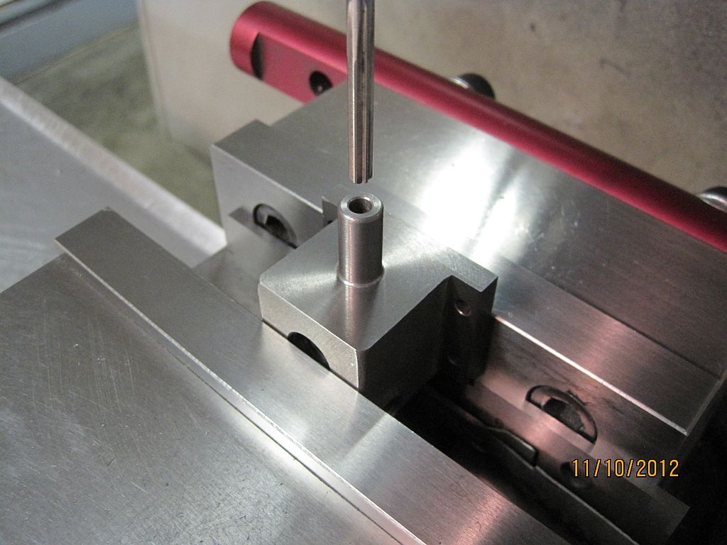
. The ports have a D shaped hole that connect the ports above and below the valve seat; well the first one on the exit side came out fine but when I did the inlet side I neglected to rotate the D 180 degrees and cut right into the valve seat. So I did things a little differently on the new casting as far as the order of operations.

ValveChest_001.jpg

Here is the raw casting after a little cleanup and a trip through the blast cabinet.

ValveChest_002.jpg

Holding onto the valve guide I was able to satisfactorily center up the casting in my little 3 jaw chuck. Working carefully the chucking boss was faced and center drilled.

ValveChest_003.jpg

The chucking boss is finished turned and the top of the casting faced off.

ValveChest_004.jpg

The casting is flipped around and the valve guide rough turned as well as the bottom being faced off.

ValveChest_005.jpg

In the mill vice the casting is squared with the side surfaces which will not be machined.

ValveChest_006.jpg

The gasket surface is cleaned up (just barely).

ValveChest_007.jpg

Using the centerline as the datum the sides are machined to match the boss on the cylinder. The mounting holes were also drilled at this time.

ValveChest_008.jpg

Back in the lathe the valve guide is turned to size and length; I removed quite a bit of material from the bottom so the chest would match its mounting boss on the cylinder.

ValveChest_009.jpg

Flipped around the chucking lug was removed and the boring and threading done for the valve chamber and plug. Most of the chucking lug was removed in the band saw first.

ValveChest_011.jpg

The print said to spot face the nut locations but I prefer the look of having the whole surfaced milled so that is how I finished the mounting flanges.

ValveChest_012.jpg

Here the water jacket ports are being faced off.

ValveChest_013.jpg

Spot drilled.

ValveChest_014.jpg

Drilled.

ValveChest_015.jpg

And taped 1/16-27 NPT.

ValveChest_016.jpg

Finished; same for the other side.

ValveChest_017.jpg

The valve guide is indicated in.

ValveChest_018.jpg

The valve guide is drilled and reamed.

ValveChest_010.jpg

The exhaust port is taped ¼” NPT.

I still need to do a little hand work and cut the valve seat but for the most part the valve chest is complete.

Thanks for checking in.
Dave
 
Sorry to hear of your mishap with the casting but glad that you are now back on track. As always very informative setup photos.

Vince
 
Hi Dave,
I'm happy to see you finally got a break and managed to get some time in on your Pacific project.
When I first found out you started work on it, you were already on page 8. By the time I got caught up you were in work mode and not making any progress on it. I was somewhat dissapointed, as I'm sure you were.
I hope you get the time to keep it going.
I'll be watching and hopefully learning.

GUS
 
Thanks guys,

Gus; it has been a pretty long dry spell but now that winter is just around the corner and bulk of the yard work done I hope to be back doing regular updates. I also get to rebuild a 30s vintage Aermotor windmill gear box for my brother this winter; that will be fun.

I have not been completely idle; a couple of other small parts were completed and I did take photos. So I will get them added to the build in the near future. We did a little work to improve the cross over cam. This is a purchased part from a machine shop in MT. and the original profile they were making didn't play well with the Lester's design of the follower shoe.

The new cam design works real nice and I will have some photos of it down the road a bit.

Thanks everyone for checking in.
Dave
 
Back
Top