Open Column Launch Engine from Kit

Home Model Engine Machinist Forum

Help Support Home Model Engine Machinist Forum:

This site may earn a commission from merchant affiliate links, including eBay, Amazon, and others.
Great stuff Zee - and thanks for clarifying the CRS and HO2 - without your explanation I would not have had a clue, although I'm sure most everybody else on here already knows :)

Having just got my first lathe and pillar drill, I'm practicing with various bits of metal - it all looks so easy when you see what the folks on here do, but in reality when I have a go ........ ;D

Like you, to begin with I know I'll need to scrap some bits ("practice pieces" :D), but as long as I learn from the "mistakes" and do not repeat them too many times, it's all part of the fun

Following with great interest.

Regards, A
 
Zee, best of wishes with the new build :)

I keep my "practice" ;) pieces - to build smaller engines later on :big:

Man, the mention of the Deutches Museum brought back memories - spent a couple of consecutive days riding the U-Bahn from Karlsfeld to the museum in 1999 - couldn't finish the visit in one day ;D - then a day at the Flughthaven museum, and a couple of evenings at the Hoffbrauhaus ;D

Regards, Arnold
 
Some hints for Zee and future novice readers of this thread...

Getting a good finish on 1018 can be problematic - sharp HSS tooling and sulfurated cutting oil helps. 12L14 steel (the 'L' indicates the lead it contains as a machining lubricant) machines beautifully.

Check the local hobby stores that cater to the RC folks. Often they will have a K&S metal display containing small sizes of rod in brass and sometimes copper, stainless and aluminum. While the prices are higher than the web suppliers, for a single piece they're often cheaper once one considers shipping costs and they have the advantage of immediate availability. These same shops often have pre-threaded studding in small sizes such as 2-56 and 4-40 as well.

Don't buy small screws in short lengths. Buy them in 1/2" length and cut them to needed size with a cutoff disk in a Dremel. Often a box of 100 screws from MSC will cost less than one of those packages of five (why always an odd number?) from the local HD or Lowes and you'll have a lifetime supply.

When (dis)assembling something with small parts and screws, do it on a folded, "fluffy" white cloth (I use an old baby blanket) laid on your bench top. Since the surface is "dead", small parts, if dropped, will not bounce off into oblivion and the white surface makes them easy to locate.

Two essential tools for working with tiny screws and nuts are the jeweler's gemstone holder

http://www.micromark.com/GRIPSTER-NUT-STARTER-00-10,6735.html

and a pair of pearl tweezers

http://www.micromark.com/PEARL-TWEEZER,8033.html

It's also worthwhile buying a can of liquid, brush-on (electrical) insulation. While eminently useful for its intended purpose, you can also dip the tips of a pair of tweezers into it. The resulting resilient, slightly gummy, coating will help to prevent small parts from snapping out of the jaws.
 
Thanks Alasdair and Arnold.
Thanks Marv...I like that pearl tweezer.

So I figure on 'going by the book'...i.e. the construction manual. I figure most people just starting out might go that way until they have more experience to create their own trail. Still, I need to be careful when it comes to fitting parts. I've read enough to see that you have some options like fitting the cylinder the piston or the piston to the cylinder.

Having said that...be sure to read the manual completely before starting. In this case, the instructions start having you use the mill to create the base. That's fine but later as you start to work on the 2nd or 3rd part, the author mentions tramming. 'tramming' - the art of making the mill head/spindle perfectly perpendicular to the table. Granted, it may not be critical for the 1st part but still...tools should be properly adjusted, cleaned, and checked before using.

I don't think the method they propose for tramming is very accurate. I suggest you find other methods on this forum. The manual calls for using a 'straight length of round stock' and a square. Not good enough! There's better methods that take no more effort.

Reading the entire manual may also help to identify those tools that will be needed but have not been acquired yet. One tool they use is a 'vise stop'. I could use some help here. I don't know why it's called for, what it does, etc.

As I said before, one weakness of the manual is that, although they say this is for the newcomer to the hobby, there is much that they assume. One example, is they state 'in modern times we use Datum Dimensions' rather than Linear Dimensions. What? Huh? ??? I did a quick google...pardon me while I get some aspirin for my headache...Okay. Linear is the distance between two points. Datum is the distance from a reference. A little 'linear' math should get me the Datum. Let's see, 0.31 + 1.172 is 1.482 while the Datum is 1.485. I need more aspirin.

As a side note...the writer speaks in 1st person (I think). Quote, "the only business I've found"...etc. But the author is never identified. I have no idea who wrote this. But I'll tell you one thing that really irks me :mad: is when I purchase something and it's not even been edited. The author doesn't know the difference between 'insure' and 'ensure' which is used several times so it's no typo. Yeah the price is low...but that's no reason for shoddy work.

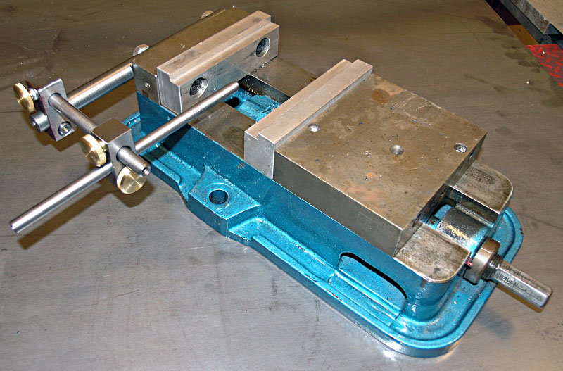
Back to the 1st part. He or she is mounting a vise to the mill's table and using a 'Dial Indictor' (no...that's the way it was spelled) to square it. The picture shows a type of indicator I don't have (but want to get). I'll cross that bridge when I come to starting the first part (oh when will that be Carl?). I don't know what you call the thingies on the vise that do the actually gripping...but while the vise itself was square...they were not.

The first part calls for a 4-Flute cutter. But no mention of size. Sigh. While the manual talks about 'flex' and 'finish pass'...there's no mention of 'climb' cutting. I'll try to address that when I start the first part (oh when will that be Carl?!).

Another irksome thing is the use of a tool that is referred to as 'essential'. In this case, a Spindle Stop. But it's custom made!!! That should never be part of a beginner's kit!

It's good that this starts with the mill. I think I have a problem with my lathe. When I face a part...it's slightly convex. That tells me the spindle is not perpendicular to the cross slide. I've seen references on the forum to 'twist' of the bed. I don't know if that's it but my lathe is mounted on a wood desk in a basement and is probably moving around. Help here would be appreciated.

I don't mean to beat the manual up so much...the kit is $60...so what do you expect? As I've said before...I only started 4 months ago and have actually built some things. Thanks to reading a lot and being on this forum.

Okay...this is long enough. Boring without pictures. Hopefully it'll get more interesting soon (oh when will that be Carl??!!!).

I have a trip to make but hopefully I'll have something next week.
 
A datum can be a point, line or plane from which dimensions are referenced. Think of it in terms of an origin. The term seems to be more often associated with GD&T (or geometric dimensioning and tolerancing) which is an enhancement to traditional drafting standards. Linear measurements on the other hand can be of two types...absolute (measured from a common origin) or incremental (measured from the preceeding point). Either method is acceptable, but accuracy is best served by using absolute measurements. The math doesn't change, but if using incremental measurements, if the first point (hole location for example) is off, then so will all subsequent locations. This is less likely with the absolute method.

Regards,
Bill
 
Zee,
Sorry to see that you're getting a little frustrated. It's easy to do
when something as large as this hobby is started.
One thing you'll need is a dial test indicator. LMS as well as others
have this. This is probably what you see being used to square the
vise. You'll use it to tram the head; what you'll want to do is have
the body of the indicator parallel to the table and tha needle
pointing down somewhat. Move the spindle down till the needle touches
the table at one extreme side or other and then down a little more to
center it in it's travel. Lock the spindle/head assy and rotate the
spindle to the other side. Make sure the indicator doesn't "bottom
out" or leave the surface of the table. Move the column HALF so the
indicator moves HALF the difference. Go back and forth until you get
it the same.
Don't worry about a vise stop. It's purpose is to locate multiple
parts identically. Making a one off it won't matter.
Don't worry about linear vs datum dimensions. As long as you have
dimensions to work with you'll be OK. Hopefully they'll all be from
the same corner. (I just vented about Elmers dimensioning in another
post).
The spindle stop. I'm thinking its to hold the spindle from rotating
when you change tools. you should have gotten a wrench with the mill
for this purpose.
As far as the size question on the endmill, it isn't that important;
use what you have that is "size appropriate", that is don't use a 1/8"
mill to side mill a pc of 3/8" thk material. Just leave .005/.01" for
a finish pass and you should be fine. Try climb and conventional
milling to see what works best for you.
Hope this helps. I'll post some more general info in another post


Mark

edit: just read Bills reply, very concise
 
OK, so much for the specifics. This can apply to anyone new to our hobby or to the techniques we use.
Not sure how much detail the construction manual gets into, but a few thoughts.
Now, I've been the trade for 35 years, but I'm a relative newbie when it comes to what we do here, so I've had to relearn some things. I can do things much differently at work owing to the machine difference.
First is, learn what you can expect from your equipment. What I can do at work resembles nothing about how I do at home in my shop. Try different things and make a mental (or written) note about what worked best. There can be several correct ways to do something. I'm constantly learning what I can and cannot do.
As a learning experience, try to make non-critical parts much better than they need to be. You will probably see parts toleranced to 1/32" or .010 on your plans. Try your hardest to make them to nominal. If you miss it may still work, but try to make the simple parts "dead on". Also start with the easiest parts. You may not get them within .001" but getting them close will give you confidence before you start the harder stuff.
Most of all, enjoy it! This is a very rewarding hobby, so don't burn out on it and ask questions if you're uncomfortable with something. There is a lot of talent here on this forum willing to help
Oh yeah, we love pictures! :big:
 
A vise-stop (also called a 'backstop') is a fixed piece (often attached to the vise somehow) that parts can be slid up to and clamped. If you're, say, drilling the same hole in a dozen parts, setup the first one against the stop, locate and drill it, then remove it and replace it with the next part.. seat it against the stop and drill.. rinse, wash, repeat.

Even if you aren't doing repetitive parts, I find them handy when using DROs as well since you can zero off the stop and then drive around to the coordinates you want to go for different parts (it works as well for handwheels, but is a little more complicated to manage)

Here's a couple pictures of various stops--

Flywheelspot.jpg
TappingCranks.jpg

The black bit is a cheapy stop that clamps to the vise jaws. I usually zero on the right side of it (it's convenient for that since it has a nice flat side to run an edge finder into).

Here's a fancier one from Bob Warfield:

P7123547.JPG


They don't have to be fancy.. Bogs (an excellent backstop advocate) mentions supergluing bits of stock to the vise sometimes to act as a stop.

 
zeeprogrammer said:
It's good that this starts with the mill. I think I have a problem with my lathe. When I face a part...it's slightly convex. T

I had that problem, ran me up a wall for a time. I was using the lead screw to get the bit up to the material, then i'd back it off a bit and used the compound slide screw to bring it back in. So if I turned the crosslide wheel clockwise I was slowly sucking up the lead screw backlash pulling the bit away from the material. To avoid that now I try to remember to keep all the various feed screws loaded against the direction I'm turning the crosslide. Installing some thrust bearings at the lead screw bearing block cut a lot of the play out, its just a quirk of the machine that if not properly addressed with spiteful glee, say "Howdy"

If I got the terminology right it might make sense :)

I see why a lock down device is useful to prevent that inevitable creep. I'm sure machines built these days have such a device built in. Mine from the days of the dinosaur is lacking some of those bells and whistles.
 
zeeprogrammer said:
Okay...this is long enough. Boring without pictures. Hopefully it'll get more interesting soon

Don't worry - I find it highly interesting already, especially with the replies from Bill, Mark C, shred and Foozer - cracking stuff for a beginner to have explained without being at all patronising.

Have a good trip, A
 
Zee,

Don't worry toooooooo much about ending up slightly convex when doing a facing cut using a lathe. All the advise given is excellent especially the point referring to removing backlash from feed and lead screws. What happens, particularly with a heavier cut is that the load on the tool increases as you approach the centre, because the rpm and (powered), cross feed are constant but the cutting speed, (ft/min), slows down as the diameter gets smaller and is zero on the centreline, in other words the last itty bitty piece is chiseled off by the cross feed. Even with everything locked down there is still a tendency for the tool to move towards the tailstock. Very light cuts, (max 0.005"), as you get close help reduce this load.

Hang in there buddy, it's all downhill from here.

Hope this helps. ??? ???

Best Regards
Bob
 
Bill: (Linear vs. Datum) Thanks. Am I being too picky? Shouldn't the 'linear' math' have given me the same datum point instead of a difference of 0.003? Why shouldn't it be 0.000?

Mark: (frustrated) Oops. I was afraid of that. My apologies to everyone for giving the wrong impression. While it may appear that I whine/whing/rant a little...I'm really enjoying this immensely.

Mark: (dial indicator) Very happy this came up. I realized that my method for tramming the head was inaccurate (and frankly stupid). I'll have to correct that before I continue. As for the vise..I don't see how I can mount the kind of dial indicator I have to do that. So last night I ordered one from LMS that should work for me.

Mark/Shred: (vise stop) That's what I thought. It also looks like the author is using it to ensure the part doesn't move when milling against one end. Thanks Shred for the pics. That helped a lot!

Mark: (spindle stop) Oops again. Here I am talking about the mill and then I moved on to the lathe without warning. What the author calls a spindle stop is a thingie that mounts through the spindle of the lathe and is attached to the hole above the gearbox. I expect it's used like the vise stop...(see above)...but for the lathe. I think I can get by without it when I get to cutting (geesh Carl...when will that be?!)

Mark: (tolerance) Good point. I do try to hit nominal. This reminds me of some questions...the manual says things like 'a 2-place decimal so the tolerance is +/- 0.010'. Later I see that 3-place decimal has a tolerance of +/- 0.005. Neither of these seem right to me. I've seen in other projects that the drawing may provide the required tolerances. Especially when the tolerance is not symmetrical (e.g. +0.005/-0.000) But what is the rule for dimensions whose tolerances are not given? Without knowing anything else (i.e. the correct thing) I would have thought the tolerance would be +/- half the next decimal position. So 0.010 would be +/-0.005 and 0.001 would be +/- 0.0005. Feel free to open hand my forehead.

Shred: (vise stop) After re-reading your reply I saw the bit about zeroing off the stop. That's a useful tip. Thanks.

Foozer/Maryak: (convex) Thanks. I'll try again. Come to think of it...I have had some problems with things moving while I crank. I got a carriage stop and a carriage clamp but haven't used them yet...I expect those will help. Maybe the tool is too far out and flexes? What else should I look for?

Alisdair: Thank you.

Several weeks ago, I snapped the studs in half that came with the vise when I tried to mount it to the mill's table. I've been using the studs from the clamping kit. I tighten at least as much with no problem so I think the original studs were defective. This is a pic of what I do now.

IMG_0088.jpg


I'd rather not use the (what do you call them?) clamps and studs. Some real long studs came with the clamping kit that I doubt I'll ever use or need as many (there's 4). Any reason why I shouldn't cut them down to use for clamping the vise?

As for the pic...I tried cropping to make the picture smaller. No go. What do I need to do? (This being the real reason why I posted the pic.)

Thanks all.
 
Get yourself a (free) copy of Irfanview

http://www.irfanview.com/

and use it to crop and resize your pictures to 800 x 600 pixels - plenty of resolution for forum purposes.

Your picture above is sized at 800 x 763 pixels and triggers the scroll bar.

Here's a picture sized to 800 x 600 pixels and the scroll bar isn't triggered.

MARKOUT1.jpg
 
zee, the math should have given the same result either way at least within .001 if there was some rounding like .0625 expressed as .063 on one dimension but added to the cumulative total in its original 4 decimal form. Without seeing the print I can't say for sure, but you are correct... things should add up!

Bill
 
mmmm Sorry Marv. Your pic shows with a scroll bar. I'm on a laptop but I also tried my (old) desktop.

Wait...I increased the resolution on my desktop and the scrollbar went away. I can't read anything but the pic looks great (but Albert looks like he's in a fun-house mirror).

So there you have it...I have to get younger eyes or more powerful reading glasses.

Thanks for the irfanview. I'll check it out.
 
Bill. Thanks.
A closer look at the print shows the first linear dimension to be 0.31 while the first datum point is 0.313. There's the 0.003 difference. Why they did that...I have no idea. In fact, the 0.31 linear dimension is the only 2 decimal place linear dimension. All others on the drawing are 3 decimal places. I might think typo but the dimension is drawn nicely centered between the two arrows...and...there's a second one in the Y direction.

I hadn't explained earlier...there are two drawings for each (or most parts)...one using Linear and the other using Datum. One for the young folk and one for the old folk.
 
zeeprogrammer said:
mmmm Sorry Marv. Your pic shows with a scroll bar. I'm on a laptop but I also tried my (old) desktop.

I size them to 640x480 and still trigger the scroll bar, but its my end and not the forum. Zoom in so the print can be read and you know. Scroll bars are no big thing, quick flip of the Ctrl button and mouse wheel brings the pic in full view
 
Zee,
Don't apologise for being frustrated. If there is someone on this
forum who doesn't get frustrated once in a while, I'd like to meet
him. I only mentioned that because I sensed frustration and didn't
want it to kill your entheuthiasm. Please vent and ask questions.
That's what we're here for.
I know what you're talking about with regard to the lathe spindle
stop. Again, like the mill vise stop, unless you're doing more than
one part, I wouldn't worry about it yet.
As far as tolerancing, there is quite a bit of variety concerning what
people do. What I've been used to the last 15 years or so is any
dimension without any tolerancing added is toleranced by what is
called a block tolerance, typically +/- .010 for 2 place, +/-.005 for
3 place and once in a while something for fractional. This should be
in a box somewhere in the title block. Anything tighter (or looser)
would be included with the dimension. This is what I'm used to and
there are many people out there designing things so your mileage may
vary.
I figure you probably bought a dial test indicator. This can be used
for squaring the vise and tramming the table. Wasn't sure if I was too
clear about tramming the table in my earlier post so I have included a
pic of how the indicator should be mounted.
I wouldn't cut the studs. You may want to clamp something to the table
someday. Just get some grade 5 bolts and cut off the heads for your
vise-holding studs
Again, have fun. This is a very rewarding hobby.


DSCF0006.JPG
 
Hi Mark,

Your comments regarding tolerances jibes with what the manual says. So I guess the manual is okay (i.e. it's not a typo). Never happy to follow a specification only to find the specification was wrong. (Always question...never assume the experts don't make mistakes...they do...just fewer of them.)

Yes. It's a dial test indicator. Thanks for the pic. Once I realized that my method for tramming was poor...I played around with the dial indicator I have. Swinging it back and forth on the table is a bit twitchy but best I can tell...I'm about .001 off. When I get the dial test indicator I'll check again. I'll be happy with .001 (for now...and maybe for always).

As it turns out...I asked LMS if they'd had this problem before. They said no. I didn't ask for replacements but they said they were going to send new studs. Maybe it's because I had just placed the order for the dial test indicator (and have spent a pretty good wad there in the last few months)...but I think it's just because they provide great service. I've had a missing part and received a broken drill bit and they were very quick to replace them. Thanks for the tip (grade 5 bolts)...I may need them if I get too heavy handed.

Oh...just saw your post Foozer. Thanks. I don't mind the scroll bar really. I just think having smaller pictures that will enlarge when you click on them looks better than a big honking shot of a stud (although some may disagree with that statement). And you can post several small pictures and not have to scroll down as much to get past them. Not a big deal...especially if the pics are interesting and good. Yeah...that's what I have to work on. 'interesting' pics.

 
I said I need more 'interesting pics'. This isn't one of them.

I've been waiting for a dial test indicator to get started (for the mill). It hasn't shown up and I got tired of waiting so I got started on the hose couplings and exhaust pipe. All lathe work and no dependencies on other parts for fit.

Here's some statements/questions...anyone's comments would be very welcome:

Which to use to feed the tool? Carriage or compound? If I use the compound, it seems a smooth cut is elusive due to up/down or in/out forces from turning compound handle. If I use carriage hand wheel, it seems I get what appears like a very small thread. (I've also used power feed and get a real nice finish...but you can't do this against a carriage stop.) Also...when using carriage...I can move back and forth, back and forth, and still metal comes off. I tried both a HSS tool and a carbide. Light cuts.

Here's a pic but I don't think it will help...

IMG_0104-1.jpg


I'm supposed to make a cut-off blade from a hack saw blade. (Thin...measures .023 and I need to cut a relief of 0.03). Just grind to shape. I suspect grind to look like a cut-off blade? Should the hack saw bits be ground off?

Thanks all.


Latest posts

Back
Top