Ohrndorf 5 Cylinder Radial

Home Model Engine Machinist Forum

Help Support Home Model Engine Machinist Forum:

This site may earn a commission from merchant affiliate links, including eBay, Amazon, and others.

petertha

Well-Known Member
HMEM Supporting Member
Joined
Jun 24, 2010
Messages
2,357
Reaction score
931
Intro
I’ve been working on this radial engine on & off for <ahem> more than a few years now. You may have seen some of my prior questions or random posts scattered elsewhere on the forum. Progress has been pretty slow with the usual factors - time constraints, distractions & learn-as-you go snail’s pace. I also had a few unwelcome interruptions with my machines. The drive train on my ’97 Taiwan 14x40 lathe developed problems which took some time to source parts & repair. Then shortly thereafter my same vintage RF-45 mill gearbox decided it wasn’t happy with the world. Ultimately I decided to upgrade the mill but that required some shop shuffling & electrical work.

Anyway, rolling time forward to present day, I might actually be on the home stretch. So I figure it’s a good time to post my prior construction journey and transition into present day work so it will appear as a normal, continuous construction exercise. Actually, looking back at some of my pictures & notes leaves me wondering what I actually did myself, so this documentation exercise will benefit me as well.

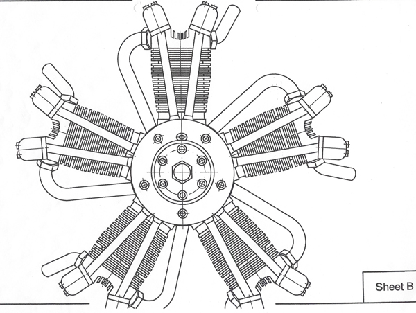
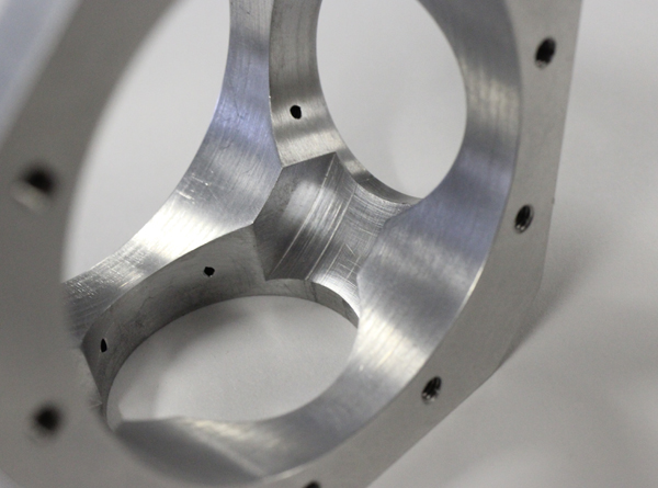
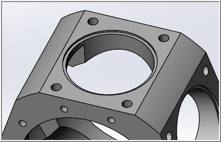
I really wanted to build a radial and avoid castings to mess up, so 5 cylinders is kind of the minimum order, at least of the more common radial plans available. The Ohrndorf seemed well designed from my amateur comparisons to other 5-cyl radials. Nothing stood out as radical or unconventional. There is a YouTube video of it running. Hard to tell, but possibly it is an early prototype. I liked the overall proportions & some aesthetic features. Anyways, it ticked most of the boxes for me at the time.

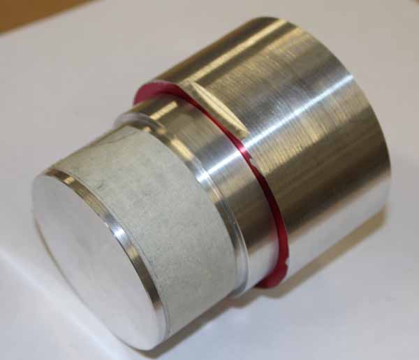
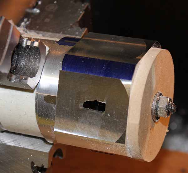
Experience wise, this is my first engine. I’d made a few prior metalworking gadgets, but nothing remotely close to this level. I decided to attempt a single cylinder assembly prototype and if that turned out OK, then I’d carry on with the rest of the engine. The engine has yet to run, so we’ll ultimately see if that path was the right decision. Wish me luck!
 
Design
The engine is designed by Martin Ohrndorf of Modellbau & Technik (Germany). On his web site he offers various other plans if you are so inclined (no personal affiliation). There are also some YouTube videos of his engines running.
https://www.engineman.de/https://www.engineman.de/produkt/bauplan-5-zylinder-sternmotor/
Engine Specs
Methanol fuel, glow plug ignition
Bore = 24 mm
Stroke = 22 mm
Displacement = 50 cc (10 cc per cylinder)
Weight ~ 1900 g
RPM ~ 950 – 5,500
Outer diameter ~ 225 mm
Length ~ 165 mm
Propeller size 18x14 to 22x12 inch
 
Plans
The 2D hardcopy plans are most certainly derived from a 3D CAD model. They are metric dimensions, corresponding to metric components & tooling. The instructions are in German & quite brief, however I was able to occasionally communicate with Martin by email to answer the odd question.

Once I had the plans, I set about re-drawing parts into my own CAD model. This isn’t a necessity but it certainly helped me on multiple fronts. I was better able to understand the assembly details, make my (imperial dimensioned) shop drawings, design jigs & fixtures etc. Ultimately I made a few changes here & there which I’ll detail, but for the most part stuck to the original design.

I’ll use the abbreviations O5 & O9 for the (Ohrndorf) 5 & 9 cylinder engines respectively. The 05 shares about half its parts with the 09. Unfortunately you need to purchase both O5 & O9 plan sets in order to build the 05. I suspect the O9 came first & the O5 later. The O5 plans have a pseudo assembly sheet that specifies whether to use a stock O9 part, or modify an O9 part, or make a new O5 part. This involves a bit of juggling to keep straight. A single set of O5 plans would certainly have been more convenient, but it is what it is. Who knows, maybe I’ll build the O9 one day.
 
Plans overview
 

Attachments

  • O5 plan cover_edited-1.jpg
    O5 plan cover_edited-1.jpg
    174.2 KB · Views: 286
  • O9 plan cover pic.jpg
    O9 plan cover pic.jpg
    131.8 KB · Views: 277
My reconstructed CAD pics. Missing pushrods, carb, inlet/exhaust accessories & some other bits...
 

Attachments

  • SNAG-1-12-2021 0004.jpg
    SNAG-1-12-2021 0004.jpg
    99.1 KB · Views: 257
  • SNAG-1-12-2021 0006.jpg
    SNAG-1-12-2021 0006.jpg
    95.4 KB · Views: 277
  • SNAG-1-12-2021 0008.jpg
    SNAG-1-12-2021 0008.jpg
    82.5 KB · Views: 291
Construction & Design
The engine is bar stock, no castings. Hardening is required on some specific parts. Remaining commercial components include metric fasteners, bearings, spur gears, ring gear, O-rings, circlips & such. I planned on cutting the spur gears for the learning experience, but ended up purchasing them along with the internal (ring) gear because all the gears require modification. Apparently ring gears are a bit involved to (properly) cut teeth profiles in the home shop. I found all the gears readily available at MÄDLER - your expert for power transmission elements | MÄDLER Webshop

RC glow plug ignition was my preference on a first build because it seemed simpler than spark in some respects. I have some RC experience so maybe it was more the devil you know, albeit no prior involvement with multi-cylinder engines or radials. I’ll have to figure out an igniter system when the time comes.

Lubrication is somewhat similar to other glow engines, oil is premixed with the methanol fuel. Specific to the O5, intake charge enters from the rear mounted carb into the crankcase where it mists over the moving master/link rod assembly, then flows backwards out through the induction tubes into the heads. One unique feature of the O5 is that the nose case is compartmentally sealed from the crankcase & partially filled with oil bath for the planetary gear train & cam plates to splash in. I liked this concept because it mitigates an oil pump system. But I’m also wondering what keeps oil from seeping out past the lower, submerged tappets (cam followers). He uses the same bath philosophy on the larger O9, although there seem to be seal differences between engines. Alternately, other glow radials allow the intake mist to continue further forward, flowing into the nose case via openings in the front gear plate. This option is still available to me with some modifications. So I’m still mulling this issue over in terms of how to proceed. I assume the rocker assembly gets lubricated by occasional maintenance oiling & fuel residue working its way between the valve stem & guide. At least that’s how commercial RC 4S engines seem to work.

The pistons have a single compression ring. My plan all along was to use commercial RC rings, specifically from an OS-56-4S engine because the nominal bore dimensions are very close to the O5. I thought this might provide some insurance against making inferior rings & experiencing running problems. I just assumed by matching the O5 bore & piston geometry to the OS-56, I would be good to go. What I didn’t appreciate at the time is that this construction path actually requires more exacting work on multiple fronts, but I’ll save that for later. I still intend to make my own rings because that’s part of model engine building. Whether it’s worth swapping them into this engine to see the difference remains to be determined. Because the liners are also cast iron, I assume they will run in together with the rings, as opposed to commercial RC liners which are typically hard chromed. I’m not sure I will ever fly the engine so I doubt I’ll wear them out between the test stand & trophy shelf.
 
I've wondered for some time if it might be possible to make a kind of a cross between a glow-plug and a spark ignition. It should be possible to turn on the glow plug during the compression/power stroke and turn it off the rest of the time. That way you'd only have the load on the battery for one glow-plug at a time, not all of them. Your battery could be a lot smaller and your plug driver would only have to carry a fraction of the load. At least compared to keeping all the plugs hot all the time it would be a fraction of the load.

I think it would be possible to either run a mechanical points/distributor configuration, or an electronic distributor-less configuration that would just require a crankshaft position sensor.

Don
 
Don, I think this same hybrid glow plug / spark hybrid issue was already discussed in post #11 & possibly elsewhere?
https://www.homemodelenginemachinist.com/threads/running-1-4-scale-v-8.32541/#post-346879
As mentioned, my own guess is you will never get a glow plug wire element to pulse on & off with sufficiently short duration to match the timing required of an engine. They are fundamentally different systems. In a spark plug the arc will jump the open gap when high voltage is applied. Its over with in a nanosecond? Glow is an inline resistor so once lit, it will have some defined thermal cool down period. At least that's how I visualize it.

The closest thing I've heard is glow plug igniter modules that deliver different current level modes like: high for start mode, med/low for low rpm mode, zero for running mode. I've heard the Seidel radial engine glow module works this way but haven't delved into to myself. I suspect throttle would be programmed to power glow power output maybe like a commanding a speed control to a motor. But I have never seen a timed on/off glow ignition configuration like you are wondering about. I think when you hear 'switching' or similar words its referring to electrical engineer speak - pulses on the voltage regulator side. But the end result is essentially steady power to the glow plug filament. Hope this helps.
 
Last edited:
Crankcase 1. The crankcase is made from 2024 aluminum. My notes show that I started the first one in 2017, but there were a few binners along the way.

The turning operations went well, but I ran into issues cutting the cylinder facets. Possibly the setup shifted slightly. But I suspect it was my poor choice gripping the fixture OD with a 3J chuck and/or not properly confirming things where it mattered. Near the end of cutting depth, I noticed the facets were not breaking through quite equally to the internal master rod clearance groove. Not a good sign. Since the internal groove was turned in the same lathe operation as the OD, it could only mean one thing – radial runout. Therefore the facets were not equal distance relative to the CC centerline. Therefore each cylinder assembly would end up slightly up or down & a domino effect of bad things thereafter; piston geometry, compression ratio…. That that would never do. Lesson learned. Aluminum Gods = 1 point, Apprentice = Zero.

The dud part did provide some utility value. I used it to go through the motions of boring & finishing the cylinder skirt holes to tolerance as I was kind on new to boring head operations.
 

Attachments

  • IMG_0921_edited-1.jpg
    IMG_0921_edited-1.jpg
    33.6 KB · Views: 259
  • IMG_0929_edited-1.jpg
    IMG_0929_edited-1.jpg
    45.6 KB · Views: 252
  • IMG_0922_edited-1.jpg
    IMG_0922_edited-1.jpg
    33.8 KB · Views: 284
  • IMG_0932_edited-1.jpg
    IMG_0932_edited-1.jpg
    44.6 KB · Views: 273
  • IMG_0933_edited-1.jpg
    IMG_0933_edited-1.jpg
    39.1 KB · Views: 257
Crankcase 2. Turning operations went good. Repetition builds confidence. This time I reverted to an independent 4J chuck for the radial operations to ensure no runout & tight grip. I also made some improvements to the mounting plate. Radial & axial runout was confirmed, this time the facets came out good. The cylinder liner holes were bored. Then while tapping the proverbial last hole (or thereabouts) for the cylinder flanges, I experienced the dreaded broken off tap. ACK!

It was entirely my own fault. The holes were blind end M3 thread. A bit finicky but nothing onerous. After feeling quite confident with my shiny new tapping head, I decided this would be a good application. However, in hindsight, I didn’t properly factor the over-depth allowance as the instructions clearly convey. So with tap firmly stuck in hole, what now. I tried drilling on the end with a carbide, no go. I tried heat. I didn’t have access to EDM or anything like it. After some forum Q&A and very convincing YouTube testimonials, I decided to try the alum solution. It was a disaster. The process slowly turned the part into something that resembled an artifact from the Titanic. The tap was eroded slightly smaller, but still there. Rather than take up more space, I’ll just insert a few choice R.I.P. pics if you want to read the original saga & we’ll carry on with the build. Aluminum Gods 2 points, Apprentice still zero.
https://www.homemodelenginemachinist.com/threads/broken-tap-in-aluminum-cranckase.26470/
 

Attachments

  • 2021-01-19_21-03-13.jpg
    2021-01-19_21-03-13.jpg
    42.7 KB · Views: 256
  • IMG_0616_edited-1.jpg
    IMG_0616_edited-1.jpg
    50.9 KB · Views: 256
  • IMG_0617_edited-1.jpg
    IMG_0617_edited-1.jpg
    45.2 KB · Views: 254
  • IMG_5801_edited-1.jpg
    IMG_5801_edited-1.jpg
    37.6 KB · Views: 242
Crankcase 3. After 2 warm up exercises, this was the keeper. Well… maybe. Dimensionally everything was good but as I look back on the pics of so-so thready finish, I think my lathe was trying to tell me something even at that point. Forewarning of ominous events around the corner. Anyways, pleasant thoughts for now. This is how it crankcase making SHOULD have gone.
 

Attachments

  • IMG_5522_edited-1.jpg
    IMG_5522_edited-1.jpg
    52.8 KB · Views: 232
  • IMG_5524_edited-1.jpg
    IMG_5524_edited-1.jpg
    38.9 KB · Views: 225
  • IMG_5525_edited-1.jpg
    IMG_5525_edited-1.jpg
    36.7 KB · Views: 212
  • IMG_5834_edited-1.jpg
    IMG_5834_edited-1.jpg
    53.4 KB · Views: 252
  • IMG_5836_edited-1.jpg
    IMG_5836_edited-1.jpg
    40.2 KB · Views: 233
  • IMG_7127_edited-1.jpg
    IMG_7127_edited-1.jpg
    64.1 KB · Views: 236
Thanks for the likes. Nice to hear from you again Michael.R.

On my current crankcase I decided to drill/tap the cylinder flange holes right through vs blind. I figure the holes will be plugged with either a threaded bolt or threaded stud plus maybe a drop of weak Loctite for good measure & should provide some degree of seal. I'm going on the assumption the crankcase can never be under much vacuum or pressure because at any stage its rear end is connected to ambient via the inlet path from carb/manifold. So just trying to make it not be liquid leaky. Every RC engine I've seen has a collective puddle of oil residue in the bottom & suspect this will be no different. In fact I'm contemplating a removable drain plug. A standing puddle of fuel residue is generally not kind to parts susceptible to corrossion.
 
Crankcase Details
The plans call for a tiny 1mm section O-ring groove recess in the front face of crankcase. I think the purpose is to prevent nose case bath oil from exiting along that joint, possibly through some of the faster holes. The gear plate mounts to this face and then the nose section mounts over the plate, both also with O-rings.

As mentioned, I’m still deliberating this nose bath lubrication method & intend to do some simple leak tests with the engine assembled to help me decide. I can still cut this O-ring groove, but I’m dragging my heels a bit. I find them to be a bit fiddly dimensionally so you end up with the fit. If the ring is slightly too proud it will take extra bolt-up pressure to compress enough & still mate the parts. If it ends up too deep in the groove & doesn’t get squeezed enough, then the seal is compromised. Also the groove occurs dangerously close to the facet edges & bolt holes.

So the plan on my radar is to first try making a thin Teflon / PTFE gasket. I found some material samples that vary between only .002-.005” thick. I’m satisfied that I can make pretty clean gaskets just using a scalpel blade along the edge of a simple CAD/plywood cut out template. I may have to make a simple punch for the holes, but surprisingly even drilling the material came out OK as long as there was backing material. A gasket should provide more surface area be re-usable with disassembly.
 

Attachments

  • 9-17-2016 0006.jpg
    9-17-2016 0006.jpg
    29 KB · Views: 221
  • 9-17-2016 0000.jpg
    9-17-2016 0000.jpg
    24 KB · Views: 218
  • 1-17-2015 0002.jpg
    1-17-2015 0002.jpg
    29.5 KB · Views: 207
  • 1-17-2015 0003.jpg
    1-17-2015 0003.jpg
    43 KB · Views: 202
The O5 plans also call for an O-ring groove in the crankcase under each cylinder flange. Curiously the O9 does not have these. It kind of has the appearance of an afterthought. But if it was deemed necessary, than why wasn’t it similarly incorporated into the O9 plans? When I drew up my plans I decided to make the flanges square with no external boss & extend the liners a bit deeper into the crankcase (partially for other reasons too). The liners have a sliding snug fit so hoping this will provide additional sealing area. Also I intend to make similar Teflon sheet gaskets under each cylinder flange.
 

Attachments

  • SNAG-0049.jpg
    SNAG-0049.jpg
    23.7 KB · Views: 196
  • 2021-01-20_20-09-02.jpg
    2021-01-20_20-09-02.jpg
    35.4 KB · Views: 202
  • 2021-01-20_20-42-54.jpg
    2021-01-20_20-42-54.jpg
    31.8 KB · Views: 190
  • IMG_3742_edited-1.jpg
    IMG_3742_edited-1.jpg
    278.1 KB · Views: 186
  • IMG_3744_edited-1.jpg
    IMG_3744_edited-1.jpg
    280.8 KB · Views: 186
  • IMG_3746_edited-1.jpg
    IMG_3746_edited-1.jpg
    192.9 KB · Views: 176
Back
Top