Offenhauser Inline 4 cylinder, Might Midget Model Engine Build

Home Model Engine Machinist Forum

Help Support Home Model Engine Machinist Forum:

This site may earn a commission from merchant affiliate links, including eBay, Amazon, and others.
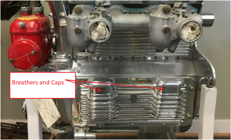
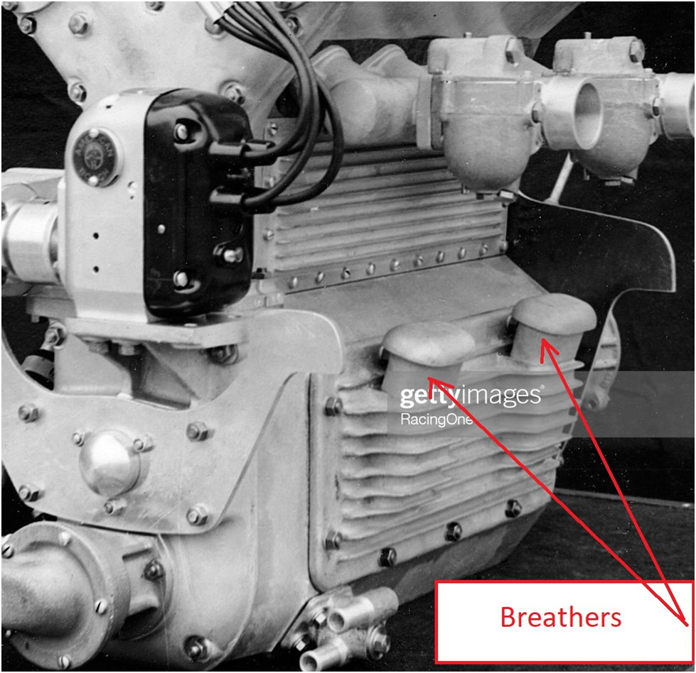
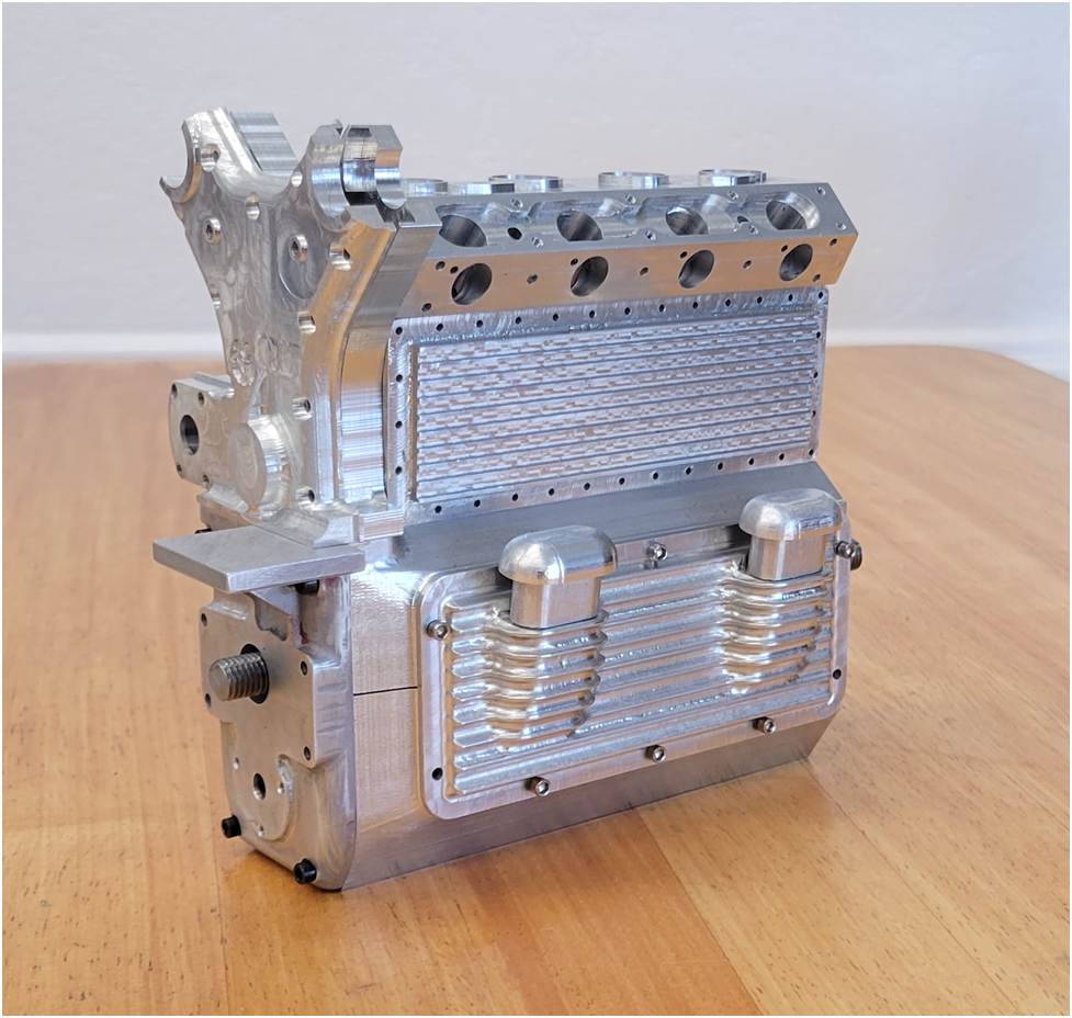
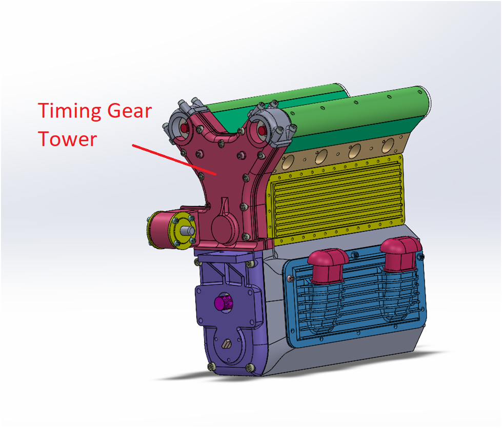
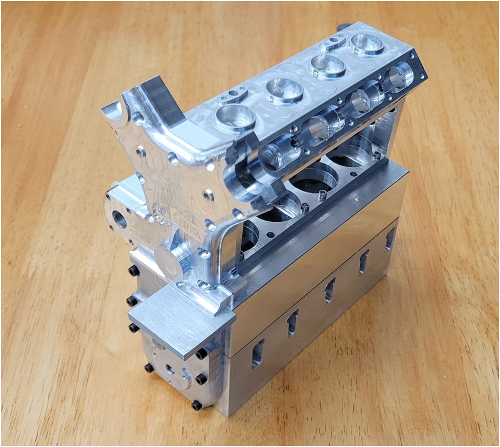
The timing gear tower houses the majority of the timing gears and is mounted on the front of the engine as shown below.

image.png

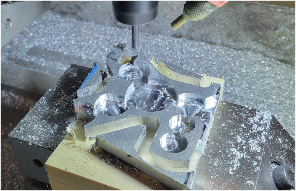
The timing tower assembly consists of a front and rear half, each holding 6 ball bearings for the gear shafts. The quality of the gear mesh is determined by the alignment and precision of the gear tower inside machining which includes not only the bearing positions, but the alignment of the screws holding the assembly together. For this reason, all of the inside machining of both halves was done first and done in a single set up. There is a fair amount of machining required on the outside face of the timing gear tower front half. This was done as a secondary operation with the work piece mounted on a fixture using the screws for alignment.

image-1.png

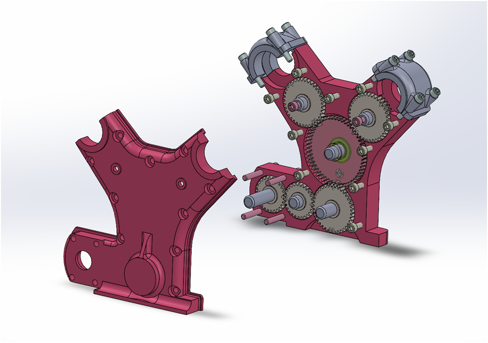
Inside Detail of the timing gear tower assembly


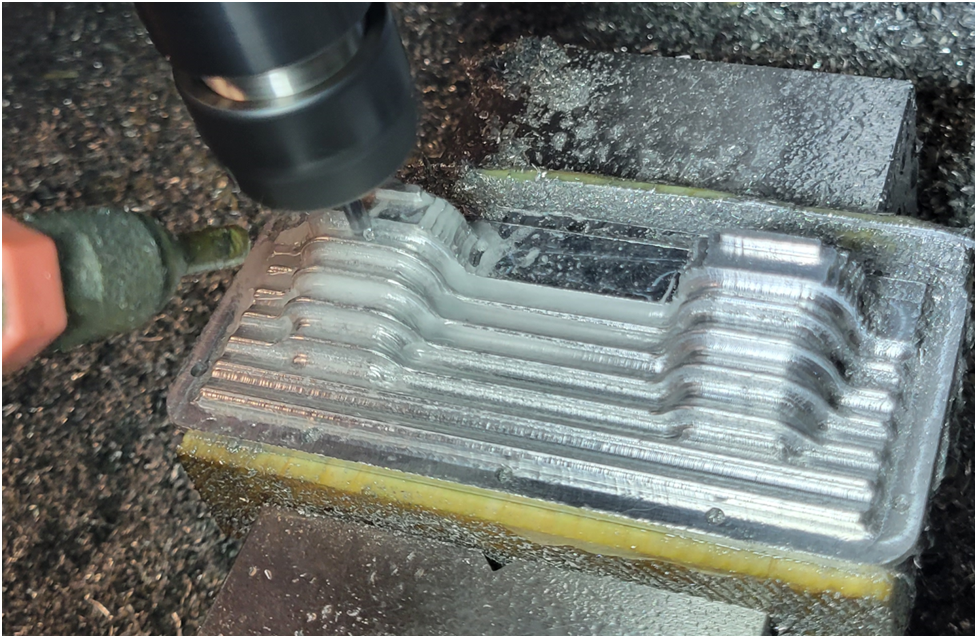
I start with the inside of the rear timing tower first as the back of the part is flat with minimal machining. Then I perform basically the same machining on the inside of the front timing tower.

image-2.png

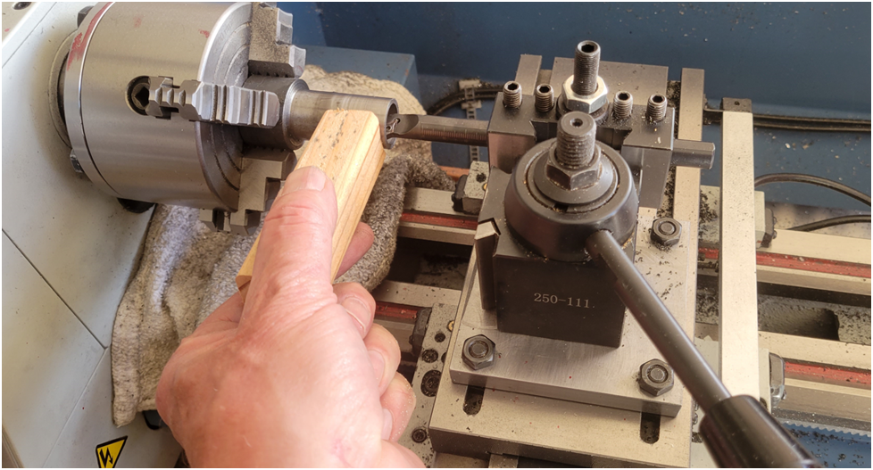
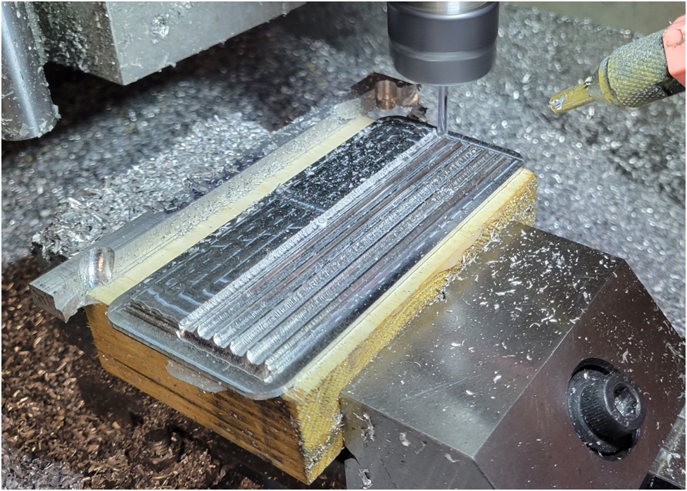
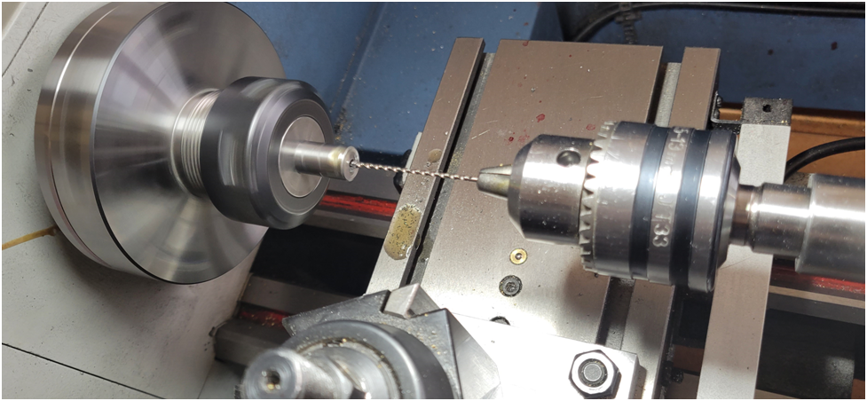
Once the machining is complete on the inside of the rear gear tower, I secure it face up on a fixture block that has been prepared by machining it flat and the screw holes drilled and tapped.

image-3.png

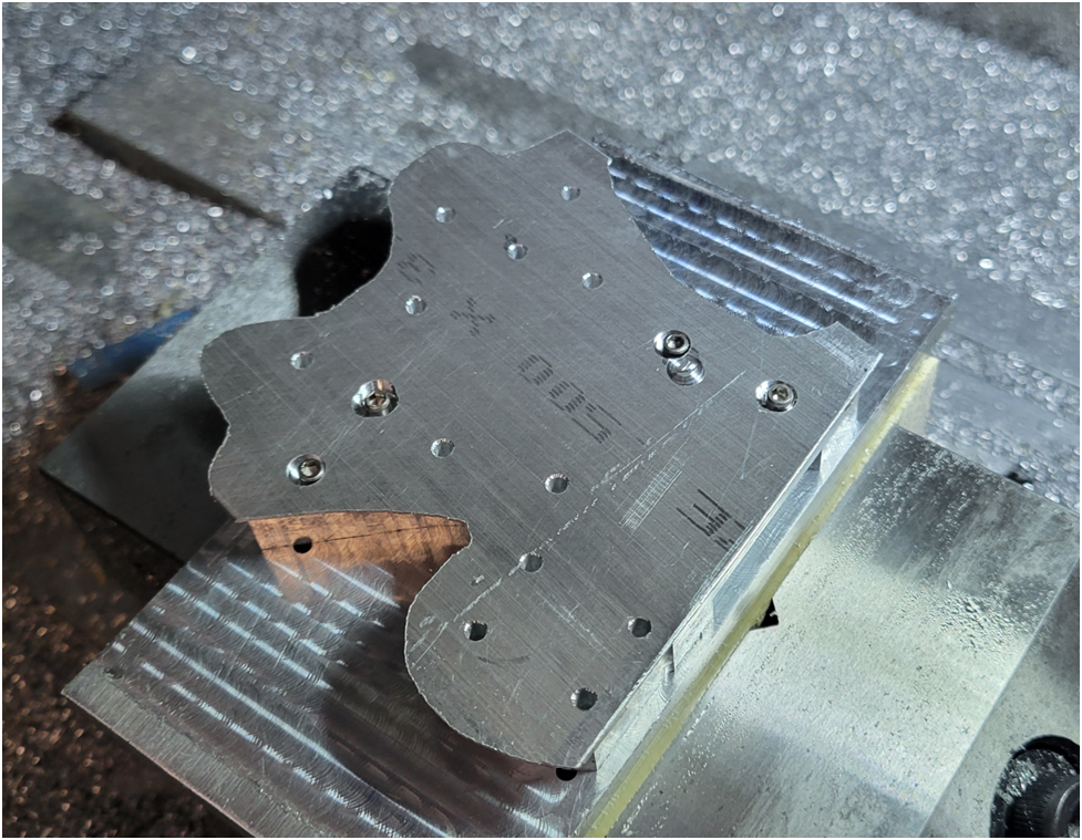
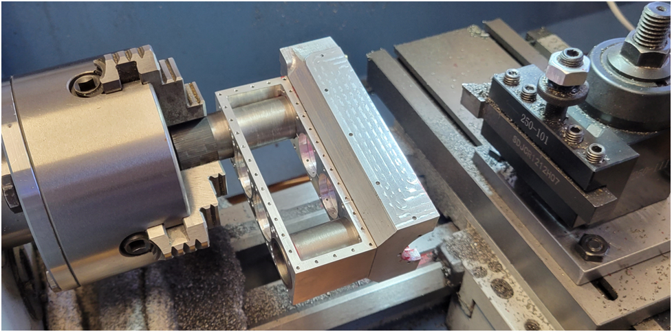
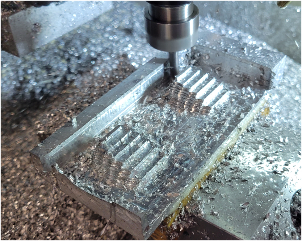
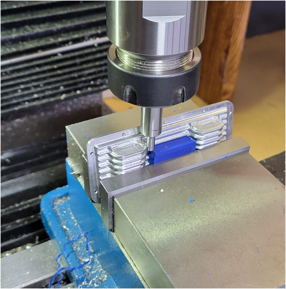
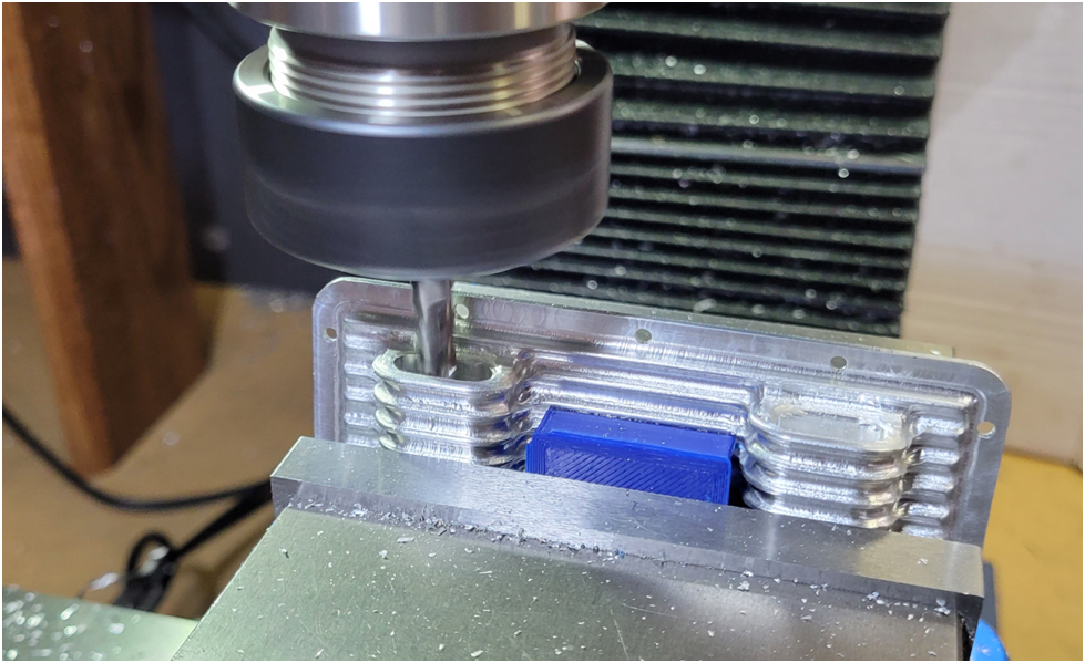
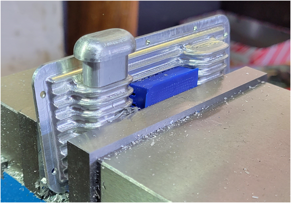
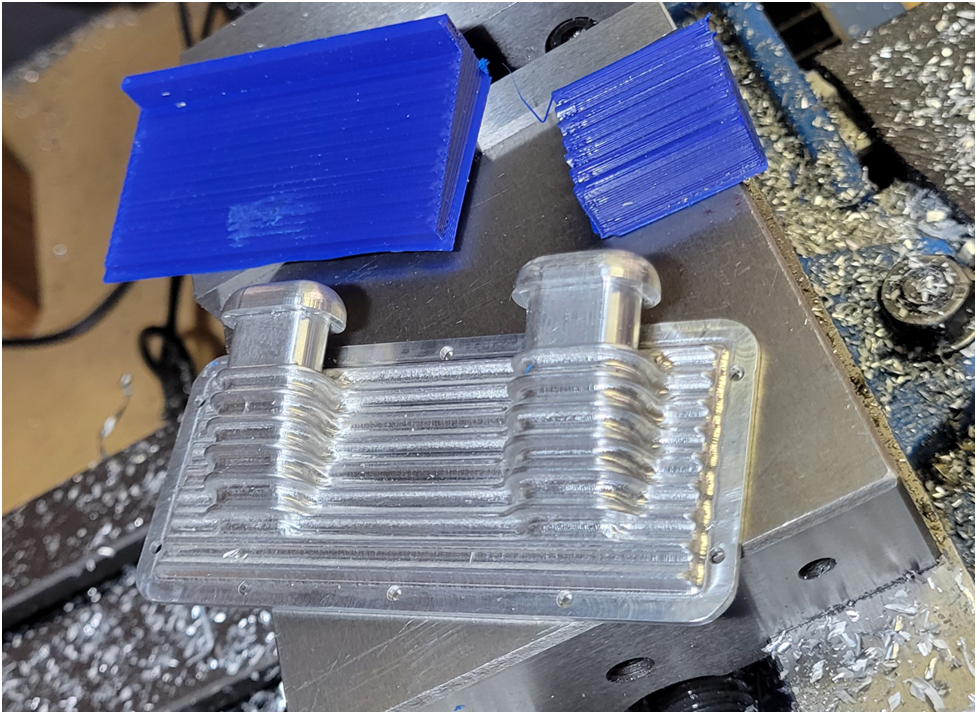
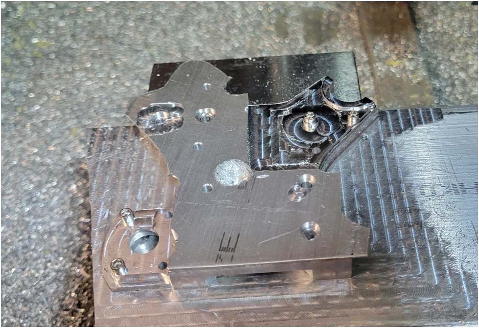
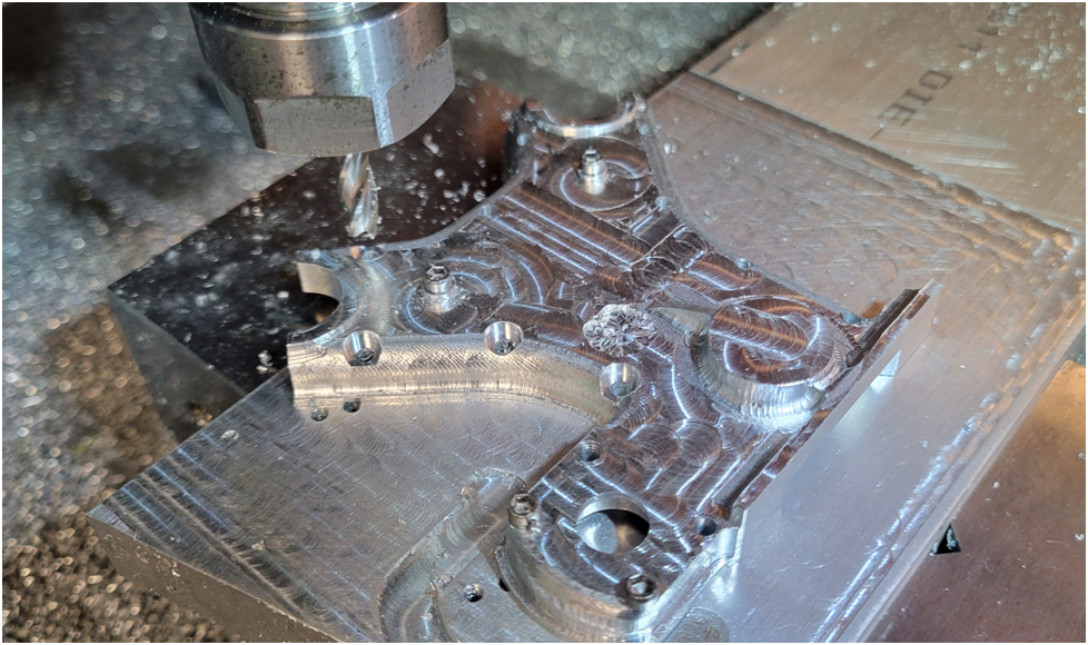
Since I needed to machine the complete front face of the gear tower, I had to machine in two separate operations because the securing screws were in the way. I secured the part to the fixture with four screws as shown in the photo, machined half, then moved the mounting screws to the area just machined and completed the secondary operation.

image-4.png

I had an error in my tool path and I crashed the end mill into the part, this resulted in a blemish on the face of the finished piece.


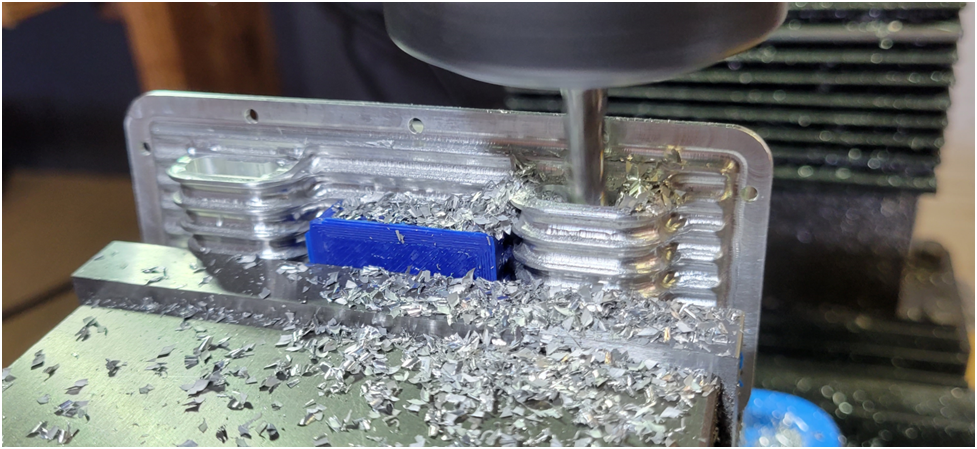
Machining of the face was accomplished with a 1/4" end mill, a 3/16" ball end mill and a 1/8" ball end mill.

image-5-780x1024.png

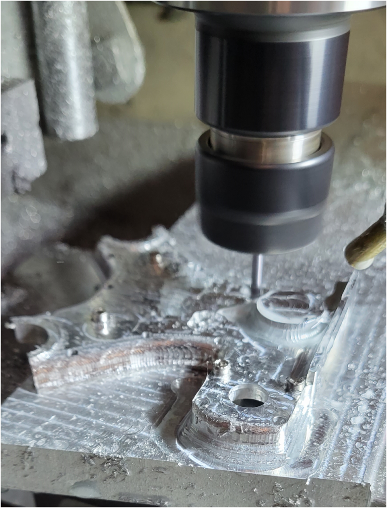
Likewise when I machined the countersinks for the mounting screws, I had to move the screws around so the work piece remained firmly mounted.

image-6.png

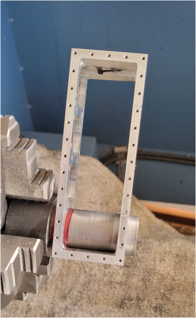
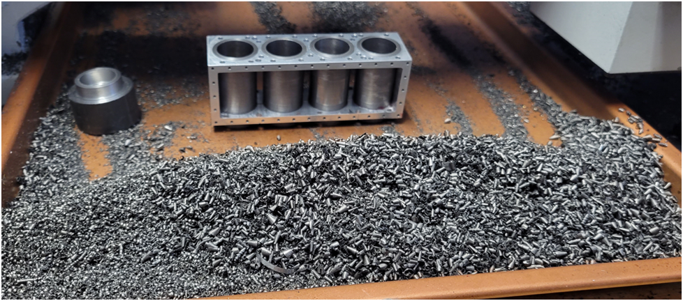
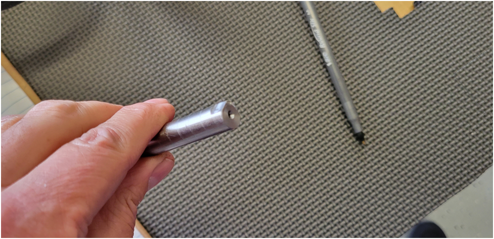
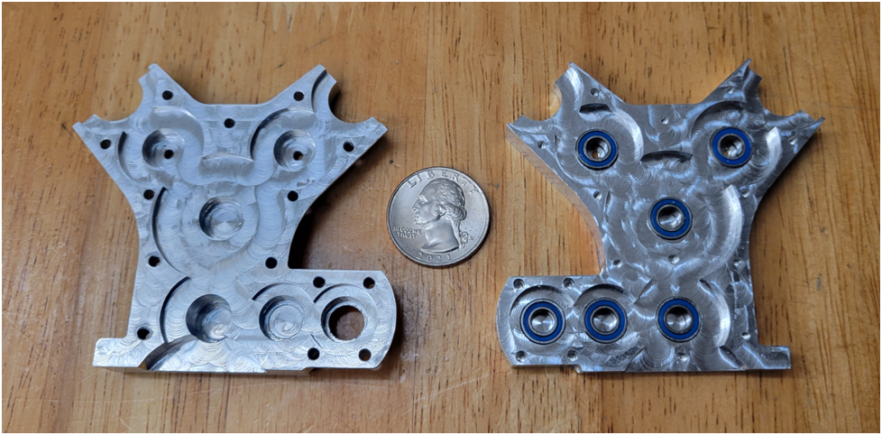
Below is an inside view of the two gear tower halves.

image-7.png

A closeup of the gear tower
image-8.png

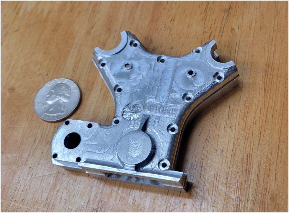
I will finish the part with bead blasting and then hand sanding to give it a used cast aluminum look, like I did on the front cover. When asked about the blemish, I explain that I machined a Carnation flower into the face as a sort of makers mark.

image-9.png
 
Offy - Block Side Plates/Crankcase Sides
Machining the sides of the crankcase was straight forward, but a little nerve wracking as the number of hours invested has grown and the anxiety of messing up has increased proportionately. Below the crankcase is being rough machined. The crankcase is assembled with the dummy crankshaft, bearings and most importantly the crankcase gaskets.
Notice how the crankcase is mounted in the vise. The datums being used are the top of the crankcase flat against the primary vise jaw, the forward face of the crankcase covered in layout fluid, and the opposite side of the crankcase mounted down flat against the vise. An aluminum round is used to press the crankcase top against the primary vise jaw to insure this datum is in alignment with the mill.
This image has an empty alt attribute; its file name is image-10.png


Below the ball end mill has completed the finish milling of the crankcase side and an 1/16" end mill is being used to "drill" the holes for the crankcase breather plate mounting holes.
This image has an empty alt attribute; its file name is image-12.png


There are two cylinder block covers that mount to both sides of the block. The one on the left side is simply a flat finned plate, but the one on the right has a small water jacket pocket and the fitting for the water flange. After machining the features on the surface, I spot drill the mounting holes. I have not had good luck actually drilling holes on my small CNC router, there is not enough Z height to get a drill chuck mounted. I kludged one up using a standard drill chuck in a collet, but the run out was atrocious. So, for small holes I spot drill, then final drill on the mill, or for larger holes I will simply mill them out with an end mill.
This image has an empty alt attribute; its file name is image-13.png


The block side plates are held in place with a large number of 0-80 socket head cap screws, I drill the .070" holes with the side plate mounted in its final position on the block in the mill vise. That is, I match drill the holes in the side plates and the block at the same time. I had to be sure to install the .020" head gasket and the .010" block to crankcase gasket to insure the spacing was correct. I tap the holes in the block and I drill out the holes in the side plates to a .089" clearance size.
This image has an empty alt attribute; its file name is image-14.png


This image has an empty alt attribute; its file name is image-15.png


Above is a picture of the engine as it stands now.
 
Offy - Crankshaft
Time for the crankshaft. I start by stress relieving the steel in the heat treat oven. I heat it to 1150 degrees for two hours, then let it furnace cool over night.
This image has an empty alt attribute; its file name is image-16.png


Notice in the image below that the compound has been replaced by a simple steel plate. The compound is the least rigid element in my bench top lathe and replacing it with this plate really helps the surface finish quality.
This image has an empty alt attribute; its file name is image-17-664x1024.png


I remove most of the material on the mill, chain drilling and edge milling.
This image has an empty alt attribute; its file name is image-18.png


This image has an empty alt attribute; its file name is image-19.png


When machining a crankshaft by turning it on centers, there is a fair amount of force created by the tail stock holding the work piece between centers. This is important as it registers the crankshaft to the center and the live center for repeatable concentric machining. I have found that the spacers used to transfer this force between the crank webs must be accurately machined to be a close fit. Too tight and the spacers actually open up the webs while the crank is machined, which springs back once the spacers are removed. Too loose and the opposite happens--in either case the machined journals are not co-linear with each other. Also, the interrupted cut can tweak the crankshaft as well, so small cuts are in order, even when roughing out the crankshaft. The spacers shown below are custom machined on the mill for each crank web and are labeled so they can be returned to the correct position.

The ball bearing can be seen test fit on its main end journal.
This image has an empty alt attribute; its file name is image-20.png


Below I am test fitting the crankshaft in the crankcase. The red Dykem is used to highlight any areas of interference.
This image has an empty alt attribute; its file name is image-21.png


Below is the crankshaft with the major lathe work completed. It is next to the dummy crnakshaft I have been using up to this point.
This image has an empty alt attribute; its file name is image-22.png


Below I am drilling the lightning holes through the center of the rod journals. These will have their ends caped and be part of the internal crankshaft oil system.
This image has an empty alt attribute; its file name is image-23-619x1024.png


Below is a cross section of the crankshaft showing how oil is delivered to the connecting rod big ends. Oil is delivered to the center crankshaft main bushing under pressure. Again, note that the ends of the big lightning holes through the conrod big end journals will be capped at each end.
This image has an empty alt attribute; its file name is image-24.png


To drill the diagonal oil gallery, the starting position of the hole is spot drill with the crankshaft horizontal at the specified point.
This image has an empty alt attribute; its file name is image-25.png


Then the crankshaft is held at the specific angle and the beginning of the hole is spot drilled again. Finally, the hole is drilled through.
This image has an empty alt attribute; its file name is image-26.png


Then I machine the keyway for the timing gear placed at TDC for cylinder #1. Indicated by the red arrow.
This image has an empty alt attribute; its file name is image-27.png


This image has an empty alt attribute; its file name is image-28.png


The crankshaft is in good enough condition to allow the test assembly of the rest of the engine. It turns true on the main bearings and I am happy with the runout of the center main journal. At some point I will need to clean the crank really well and cap the large lightning holes.
 
Eccentric
I normally glue the spacer piece in and leave it until all machining of crank is finished, that way you will not accidently build in any warp or twist.
Cheers
Andrew
 

Attachments

  • 133.jpg
    133.jpg
    98.9 KB · Views: 78
  • 136.jpg
    136.jpg
    123.7 KB · Views: 78
Enjoying your build @Eccentric
Can you elaborate on how you were validating the CS with the red dykem in the crank case? For example if it did bow in stress releif, then you would be expecting some rub on the ends of the throws? (So that means the line bore is very close to the swing diameter?).

Did you employ any special lapping tools for the journals, or just careful hand work?
 
Peter,

when I first installed the crankshaft in the crankcase there was a little interference as I turned it. I used Dykem to see where this interference was. It turned out that the corners of the crankcase are radiused and I did not relieve the corners of the crankshaft enough to clear. A small touchup of these corners on the crankshaft and all was well.
 
Offy - First Gear
The Offy has a lot of gears in the timing gear train and I want to have the gear tower populated before I fabricate the camboxes to insure I have the proper gear mesh between the gears in the gear tower and the camshaft gears. This sequence is how I make gears.
I make a sacrificial gear arbor in the lathe, putting grooves as shown for the super glue to seep into.
This image has an empty alt attribute; its file name is image-32.png


I cut the blank from the mother material, in this case brass, center punch the center. I super glue the blank to the arbor, using a live center in the tail stock to center and put pressure on the glue joint.
This image has an empty alt attribute; its file name is image-33-597x1024.png


Once the super glue is cured, I drill the shaft hole under size and ream to the shaft diameter, in this case 5mm.
This image has an empty alt attribute; its file name is image-34-719x1024.png


I don't completely trust super glue in this application so I also use a screw, not to center but to secure. So I drill and tap for a 10-32 screw.
This image has an empty alt attribute; its file name is image-35-974x1024.png


I turn the blank OD down to size. In this case we are making a 54 tooth .5 Module gear with an OD of 28mm.
The CNC is used to cut the teeth. If anyone is interested, I can provide the Gcode file to do this, it is quite simple.
This image has an empty alt attribute; its file name is image-36.png


After the teeth are cut, I turn the gear again on the lathe bringing the OD back down to the proper size. The gear cutter throws up burrs that are removed in this way. The gear is faced and the .5mm X 7mm spigot is machined.
This image has an empty alt attribute; its file name is image-37-920x1024.png


I heat the gear and pop it off of the arbor. The arbor is refaced and a pocket is machined to match the spigot.
This image has an empty alt attribute; its file name is image-38.png


The gear is again super glued into place using the spigot and tail stock to align the gear to the center of the lathe.
This image has an empty alt attribute; its file name is image-39-709x1024.png


Again a screw is used to secure the gear to the arbor and the gear is turned down to final thickness. The screw is removed and the spigot is carefully turned down, I remove .005" of material at a time so I don't bust the super glue joint.
This image has an empty alt attribute; its file name is image-40-794x1024.png


I lightly touch the teeth edges with a file to remove burrs created from the facing operation, but not much, I want to maximize the tooth engagement surface area. Finally I clean up the teeth with a piece of folded 600 grit sandpaper to clear the last of the burrs from the teeth.
This image has an empty alt attribute; its file name is image-41.png


This image has an empty alt attribute; its file name is image-42.png
 
Great work! I really like all the documentation and I know how much extra work it takes to do it. Thanks
gbritnell
 
Really nice work and I also appreciate the effort put into documenting it.

Something to think about before you get too far into brass gears. There's a lot of stress on the tiny teeth of those gears in that gear tower stack. I machined my gears from Stressproof. Ron Colona in fact had one of his 12L14 gears fail, and the broken tooth damaged some other gears in the tower. Of course, he likes to rev his Offy up to 10krpm. I'm not that brave. Ron then switched to Stressproof as well. - Terry
 
Last edited:
Thanks for the kind words George and Terry, and the advice. I have ordered a 1 foot, 1.25" round of 1144 and it will be here on April 6th. There are plenty of other things I can be working on until then. I have not worked with 1144 before and this will be a good opportunity to see what machining it is like.

I have made a few more brass gears and I am working on a depthening fixture for them. I want to make sure I have my numbers dialed in, particularly the infeed distance of the gear cutter. Brass I cut in one go, but I understand steel needs to be cut in several increasingly deep cuts to extend the life of the cutter. Surface speeds are more critical as well.

Greg
 
Last edited:
Offy – Cylinder Sleeves

The sleeves are made of cast iron and I start by removing a lot of the material on the OD, but do not bring it to final dimension. I drill most of the material from the bore by stepping up in drill sized until I am a 1/16″ from final dimension.
image-43-957x1024.png

The techniques I used to get a good finished ID included the following:
  • Used a four jaw chuck to give max clamping support on the blank cast iron work piece.
  • Bring ID to size before the OD to provide more material to stabilize the blank while cutting the ID.
  • I used an oiled stick and applied constant, but slight, pressure on the outside of the sleeve, sort of a poor man’s following rest to counter act the pressure of the boring tool. Without this I was getting about .002″ spring in the part from the start of the boring pass to the finish. See below.
  • Replaced the compound with a simple steel plate to make the carriage as ridged as possible.
  • Position the Tool post to maximize the engagement of the cross slide gibs.
  • When close to my final dimension, I used several spring passes where I do not advance the cross slide, just ran again and again
  • I ran the lathe really slow so there was no chatter, I had to go down to 280 RPM, but got really clean cuts.
  • I used the finest power feed setting. A single pass took about 6 minutes
image-44.png

As can be seen below I have achieved a very nice bore finish on the inside bore.
image-45.png

I have learned the hard way that when building a multiple cylinder engine, all of the sleeves need to have the same internal bore diameter so you only need to make one size and therefore one batch of rings.
Below I am brining the OD down to size and test fitting them in the block as I go.
image-46-633x1024.png

Then insure the OD also fits nicely into the crankcase.
image-47.png

My idea was to make a barrel hone from a section of 3/4″ aluminum rod. Turn the outside, drill and tap a hole down the middle and then split it with a saw. A taper bolt is then fabricated to provide the adjustment of the taper.
But it turned out that I put a slight taper on the aluminum rod and then used it to hone the cylinders to the same size. It was slow work, but they all came out with the same ID and nice surface finish.
Below is how I held the cylinder as I used the lathe (at the slowest speed) to turn the barrel hone.
I used 300 and 600 gm diamond paste mixed with WD40 as my polishing compound. I did get one sleeve stuck and had to take the hone assembly over to the vise and tap the hone out.
image-48-904x1024.png

The following series of photos show the diameter of the hone and the position the cylinder will slide over it, both bottom first and top first. The taper is such that the bottom of the sleeve is slightly larger than at the top.
image-49-729x1024.png
image-50-807x1024.png

bottom first, the sleeves slide up to the finished point on the hone.
image-51-662x1024.png

Below, top first and the sleeve will not slide very far because of the taper in the sleeve.
image-52-771x1024.png

The majority of my cast iron rod is reduced to chips.
image-53.png

Above the cylinder bock with the completed sleeves can be seen.
Cast iron is messy to work with, so upon completion of the sleeves, the lathe needed a good cleaning and oiling. I use Vactra Oil No. 2 for ways oil.
image-54.png
 
Offy – Crankcase Breathers

One of the most distinctive features of the Offy is its crankcase side breathers. These are highlighted in the photos below.
image-7.png


On the early engines these were quite low, over time they were raised and additional internal baffling was added.
image-8.png


Only the right side of the engine has these breathers so I start out making the left side since it is simpler. A 1/8″ ball end mill is used for the final finishing of the fins.
image-9.png


Below is the roughing pass on the right side breather plate. I left too much material on the original work piece. A tool caught it on the finishing pass and snapped, a little bit scary. The finishing tool path wasn’t aware of the big chuck of material and made an approach through it. I did not include the oversized work piece in my tool path simulation, otherwise I would have identified the issue before the run. Fortunately the part was not ruined, just the end mill and my pride.
image-10.png


Below is the finishing pass, again with the 1/8″ ball end mill running a .007″ stepover. The finishing pass took about an hour.
image-11.png


Then it is on to the breathers themselves, below is the roughing pass on the bottom of the part. I have used 2 flute end files for ever on my CNC router, but recently I have switched to three flute end mills and have been pleasantly surprised how well they work.
image-12-672x1024.png


Below is the finishing pass on the top side of the breathers.
image-13.png


the breathers are mounted in the crankcase side plates at a 10 degree angle. I made a set of custom angle fixtures with the 3D printer. On a small part as this with very light cutting forces, they work really well and are quick and easy to gen up.
image-14.png


The machining was done on the manual mill.
image-15.png


I went for a tight press fit. There will be a set screw coming in from behind the cover plate to secure the breathers. Below is a test fit.
image-16.png


Then the other side.
image-17.png


Below is the finished part along side the 3D printed fixtures.
image-18.png


The crankcase side breathers installed on the engine. I think they look cool.
image-19.png


There are a couple of additional holes to be drilled to make the breathers functional, and like the originals I am sure they will leak oil. Maybe install a PCV in them?
 
Beautiful. I recommend you always put a size reference
object in your photos. That small scale is amazing to me.
Your detail looks like it could be a much larger scale.
Thank you for the excellent posts.
Again I am amazed and impressed.
 
Fantastic work! Are the breather caps going to be functional? I would recommend having some kind of breather or it will smoke from too much crankcase pressure.
 
Anyone interested in these type engines, there is an excellent multipart interview, on youtube, with Prof. Steve Truchan. It covers bits and pieces of the history of Miller, Offenhouser and Myer Drake. Prof. Truchan overhauls and restores these engines, old Indy cars,etc.
Here's the link:

Tom Warren
 
Offy – Camshafts
The Offy has two overhead camshafts, here I will machine the exhaust cam shaft. The intake camshaft will follow the same process, but with a different cam lobe profile.
image-20.png

Cam Blank diameter .430″
Cam Base Circle Diameter .25″
Nose Radius .025″
Lift .090″
Flank Diameter . 743″
Lift Duration 128 degrees
Max Lift Occurs: 235 degrees after TDC

I start with a 5″ length of 7/16″ drill rod and drill a 1/16th inch hole all the way through for the oil feed. I drill from both ends and meet in the center. I start with a shorter drill bit and peck drill, drill a crank or two on the tail stock, retract, clear the chips and repeat. I then use a longer drill bit as shown below. I do not drive the drill bit, it is a very light touch where I am letting the drill do the work and I take up the slack with the tail stock handle.
image-21.png


Then I machine a flat on the cam shaft blank, this is used to register the lobes as shown below.
image-22.png


Below I use a level sitting on the flat to establish zero degrees on the rotary A axis.
image-23.png


Then I machine one lobe at a time, sticking out as little as possible for each lobe.
the flat can be seen below.
image-24.png


And the lobe taking shape is below:
image-25.png


When machining of the lobe is complete, I pull a length of stock from the collet, reestablish the zero point on the rotary axis, then turn to the rotary position of the next lobe, reset the zero point on the rotary axis. And run the lobe cutting program again.
image-26.png


Below is the camshaft blank with the four exhaust lobes machined.
image-27.png


Then we move over to the lathe and turn the rest of the features.
image-28.png


Below is the print and dimensions used for first section of the cam shaft, the section shown above.
image-29.png


Below I am drilling four holes in the cam shaft that will be used to register the cam gear. With another set of holes in the camshaft gear I will be able to adjust the cam timing.
image-30-489x1024.png


Then I proceed to turn the remaining bearing surfaces on the cam shaft.
image-31.png


Below is the camshaft nearing completion. It still requires some polishing of the bearing surfaces and cam lobes, as well the removal of the extra material on the far end.
image-32.png
 
Back
Top