My Version of Elmer's Beam Engine

Home Model Engine Machinist Forum

Help Support Home Model Engine Machinist Forum:

This site may earn a commission from merchant affiliate links, including eBay, Amazon, and others.

JMI

Well-Known Member
Joined
May 22, 2008
Messages
134
Reaction score
0
Location
Seattle, WA
This is my second engine. Just getting started. It is going to take a couple of months to complete because of a full plate of other things (work/family) to take care of.

P9090035.jpg


So far, so good.

Jim
 
It sure looks like a great start Jim!

Please keep us posted as it progresses.

Rick
 
Brian Rupnow said:
Looks very good! Also looks kind of familiar for some reason---

I confess. The brass bearings looked like a a good idea. I believe Picasso said:
"Good artists copy, great artists steal" ;)

Jim
 
Made a small amount of progress. Made lots of scrap pieces :eek: but not discouraged.

PB020048.jpg

PB020047.jpg


More chips to be made...

Jim

 
It looks to be coming along nicely Jim, but "scrap pieces?"
You must mean "Practice Pieces". ;)

One little tip.
When you are ready to solder the ends on the valve and piston assembles
They need to be placed through the cylinder head and guide first.
Beam%20Engine%20Valve%20and%20Piston.jpg

That is probably the most common rework issue on this engine.

Rick
 
Hi Jim,

Looks like your on target time wise ;D

Making scrap parts is good for you... It teaches you how to not do it again. But more importantly it helps you occasionally find a nice shape to use instead of or elsewhere ;D

Looks pretty good to me.... That is it looks like the starts of an engine... I can't say much more than that since I haven't built one of these yet... Some day I will need a beam engine in my collection....

Some day soon I'll start another engine....Not a beam, but an engine all the same. Where does all the free time go?! I'll keep looking at others builds for inspiration until I start mine... ;D


Keep us posted on your progress, we all need a little inspiring ;)


Ralph.
 
Its looking very good!!! Rake 60 is half right ::) ::) I'm pretty sure that the valve assembly will fit thru the hole in the cylinder top plate--I know it did on my double scale unit.---Brian
 
That is correct Brian.

The hole for the valve to pass through the head is 9/64"
The larger diameter of the valve rod is 1/8", there is .015" clearance.
Thank you for the clarification.

Rick
 
rake60 said:
That is correct Brian.

The hole for the valve to pass through the head is 9/64"
The larger diameter of the valve rod is 1/8", there is .015" clearance.
Thank you for the clarification.

Rick
I only know that because I was really worried about putting something together wrong when I built mine. Even so, its darn close!!!
 
rake60 said:
It looks to be coming along nicely Jim, but "scrap pieces?"
You must mean "Practice Pieces". ;)

Rick,

"Practice Pieces", err, yeah, that's right ;D.

Thanks for the reminder about passing the piston rod through the cylinder head prior to soldering.
Been thinking about if steel round stock is the way to go with the piston/valve rods or does brass round stock hold up well? This is being built to Elmer's original specs so the rod is kinda thin.

Thanks

Jim
 
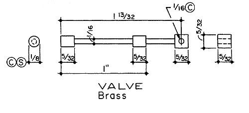
It took me 4 attempts to make that valve.
The first two broke early in the turning process because I had mistaken
a piece of thin bronze for brass.

After I found a piece of brass in the materials box the third one cut great.
Until... I got greedy and tried to take too much of a cut. ::)

Turning the stock down from 1/8" to 1/16" would probably be more difficult
using steel.

For me, a perfectly centered narrow parting tool worked best for the 1/16"
undercut areas. I kept the work very close to the chuck and cut it about 1/4"
at a time. Then I'd slide the stock out a little farther and cut back another 1/4"
until the center widths were finished.

Hopefully we will see some other suggestions here on better ways to cut that part.

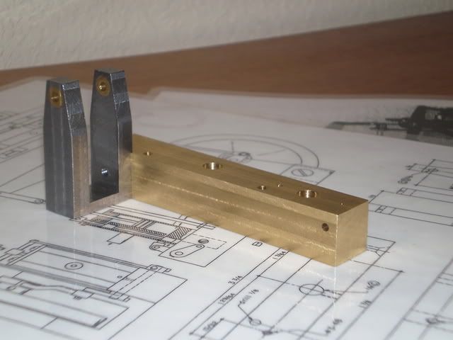
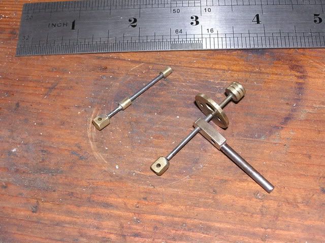
For anyone who is not familiar with it, this is the part to be made.

BeamEngineValve.jpg


Rick

 
Why "cut" it?

I made mine by soldering two pieces of 1/8" stock to a length of 1/16" rod. A U-shaped removable aluminum spacer held them at the required separation while the soldering was done. (One of aluminum's most attractive properties is the fact that solder won't stick to it.)
 
Now there's an idea I would have been thankful for a few years back. LOL

Great tip Marv!

Rick
 
I used Marv's tip after I screwed my valve up the first time by trying to file it to size --I held the file crooked and had a taper on one of the ends. Using Marvs advice, I turned down just the tapered section and silver soldered a sleeve of the correct diameter in place to save the rest of the valve. Hats off to Marv!!!
 
Perhaps this is a good example from which to generalize for the newcomers...

Just because you CAN turn/mill a part doesn't necessarily mean that you SHOULD do so. Sometimes a fabrication is easier (and may be more accurate) than machining the whole thing from bar stock.

I always recommend folks to read Kozo Hiraoka's books on locomotive building if they can borrow a copy. Even if you're not into locomotives, there's lots to be learned there from a true master at the art of creating complex parts via fabrication of simpler elements.

 
mklotz said:
Why "cut" it?

I made mine by soldering two pieces of 1/8" stock to a length of 1/16" rod. A U-shaped removable aluminum spacer held them at the required separation while the soldering was done. (One of aluminum's most attractive properties is the fact that solder won't stick to it.)

I had in mind to use round stock of the appropriate size but the aluminum spacer tip is a knock out.
Still, even assuming pre-sized diameter stock for the rods, does steel or brass have a major advantage-disadvantage or is it more a personal preference or availability issue?

Thanks for all the replies.

Jim
 
Jim,

I also went down the 'fabricated' path with my engine, choosing to silver solder brass "valves" to a length of 1/16" silver steel (drill rod) as I thought it would provide a stronger assembly. The same process was used for the piston & rod.


P8282909.jpg


Tony.
 
JMI said:
...., but darn it if these little parts are not rough on the eyes.

At that size, I can only imagine how difficult it is to see the detail you need! You have done a great job with them! :bow:
 
Rake60,
Been trying to figure out how to make the valve linkage like you did on your website.
http://www.rake60.com/beam_engine.htm
The 1/32" thick and 1/8" wide beams how did you manage those dimensions. What size stock did you start with and did you mill it down? Been searching for some 1/32" flat brass stock (by 1/8" would be perfect) but can't find any.

Any suggestions, anyone?

Thanks

Jim
 

Latest posts

Back
Top