Kaleb
Senior Member
- Joined
- Jan 3, 2010
- Messages
- 272
- Reaction score
- 27
Although Jurgen's designs have been used many times as an exercise in CAD modelling, I haven't actually heard of that many people actually building them, so I decided to have a go. After looking closely at the plans, I decided that my first choice was his beam engine.
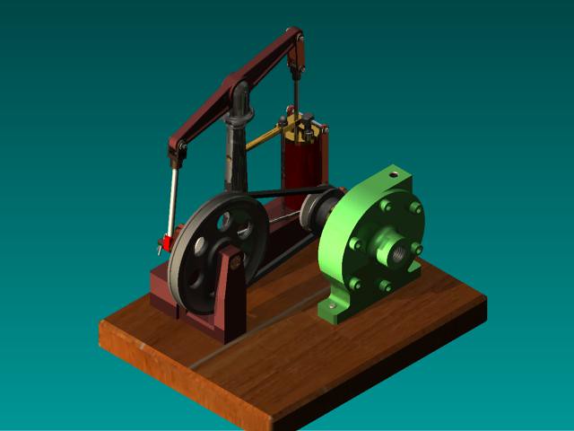
Here's a rendering of a CAD model of this engine made by a man named Jerry Koontz. I included it here to give an idea of what the finished engine should look like.
I am making some slight changes here and there to suit how I would do things.
I decided to start with the eccentric. In the original plans Jurgen has specified white acetal resin for this part, but I decided to make it from this piece of steel since I believe it will wear better, will not be affected by heat when the engine is run on steam, and besides, I have more mild steel kicking about than I know what to do with!
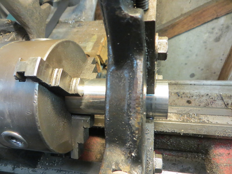
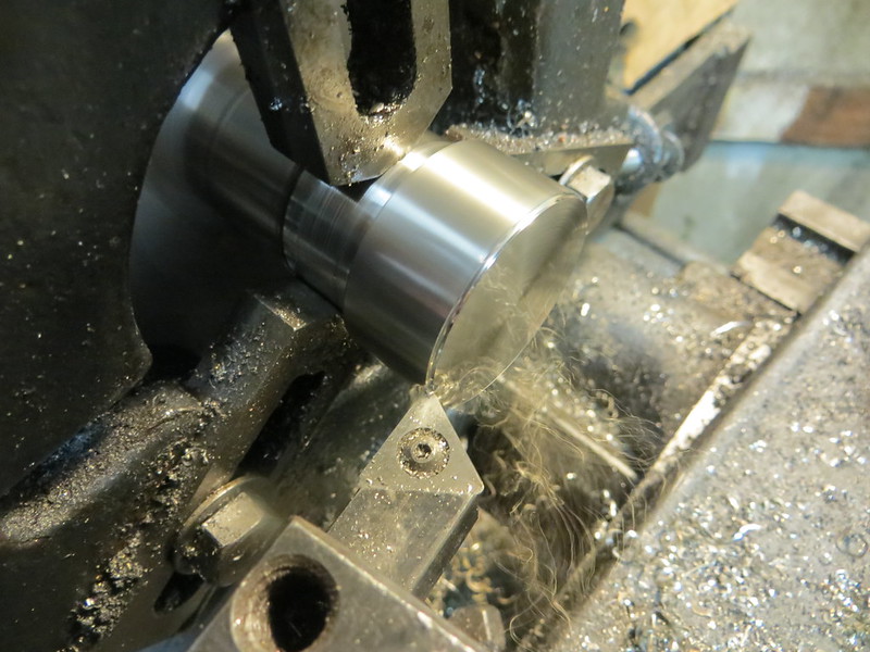
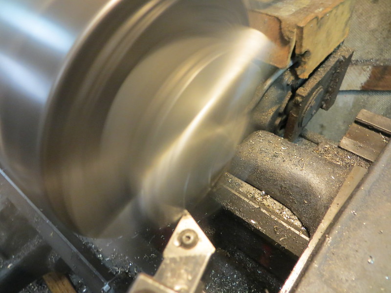
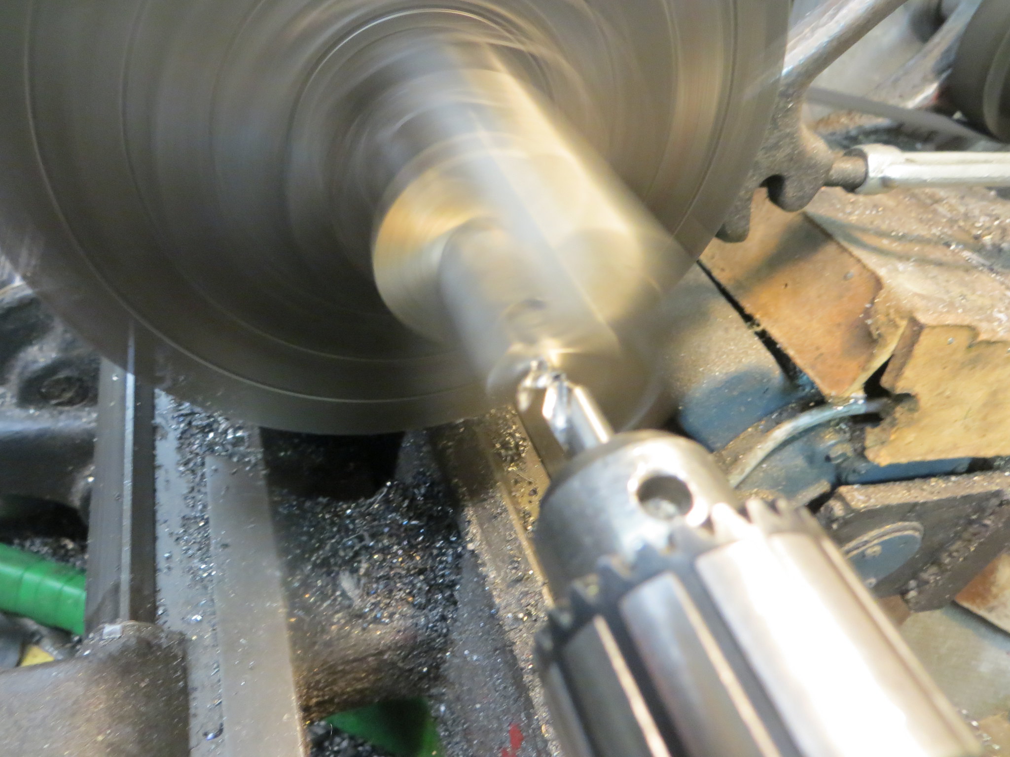
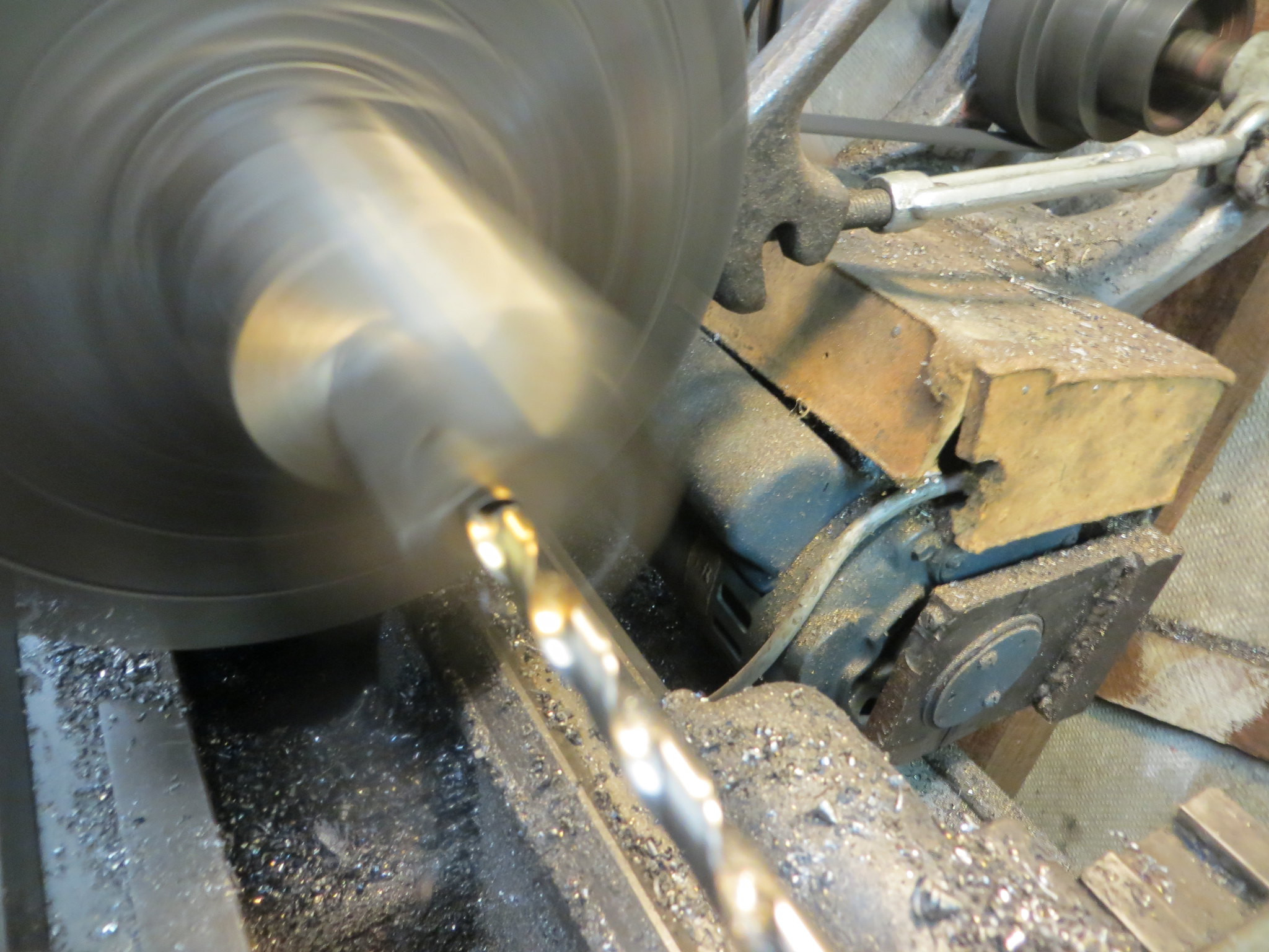
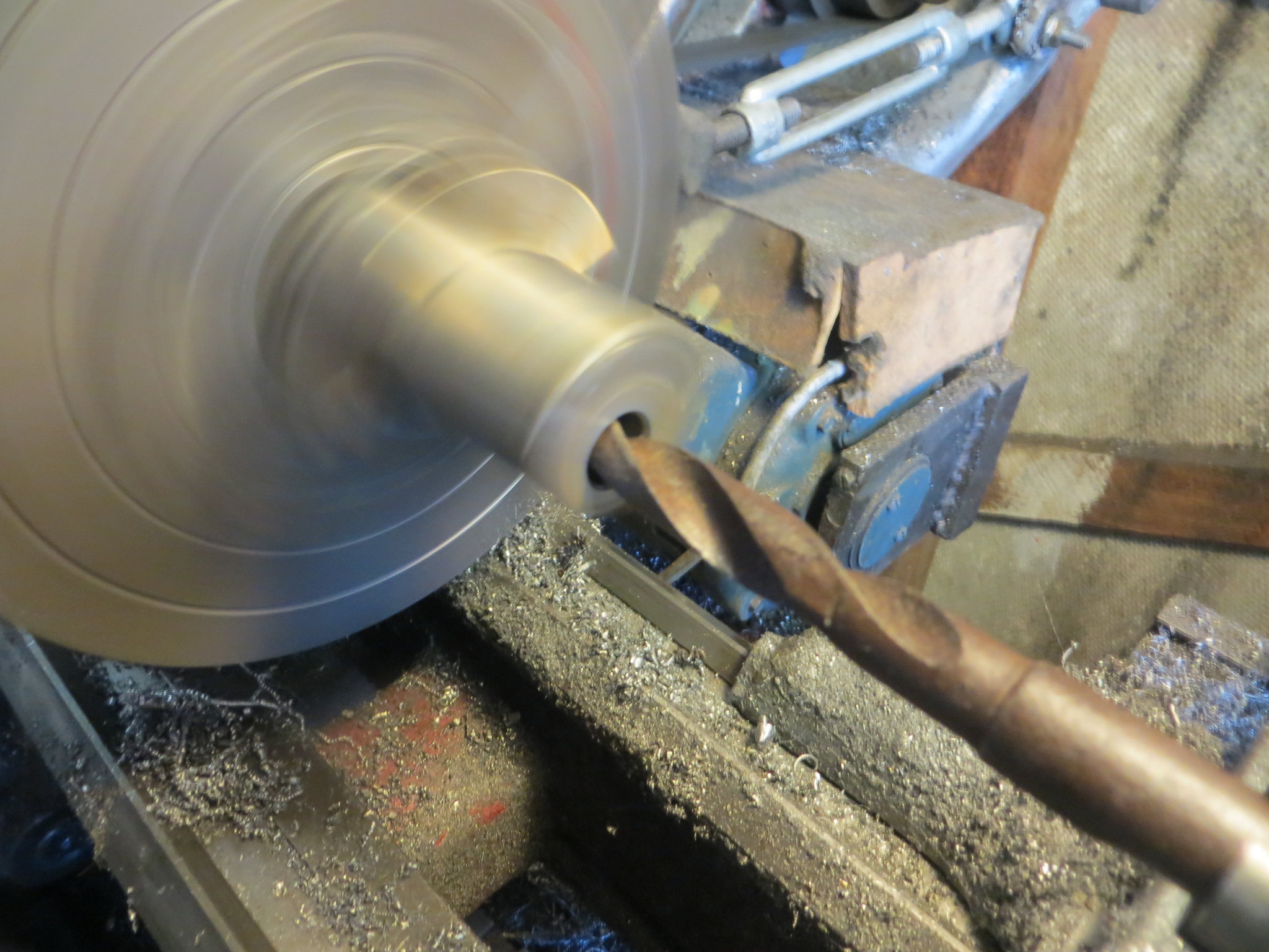
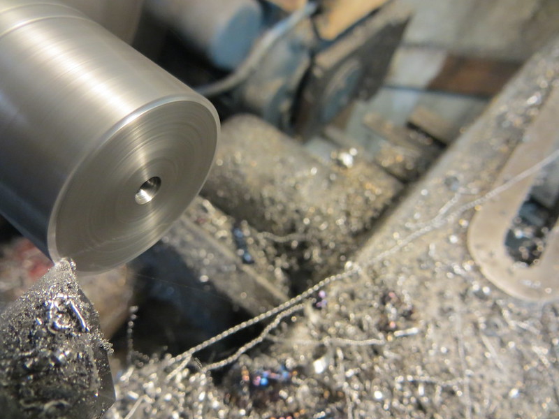
With the steady rest used to provide adequate support the work is faced and center drilled.
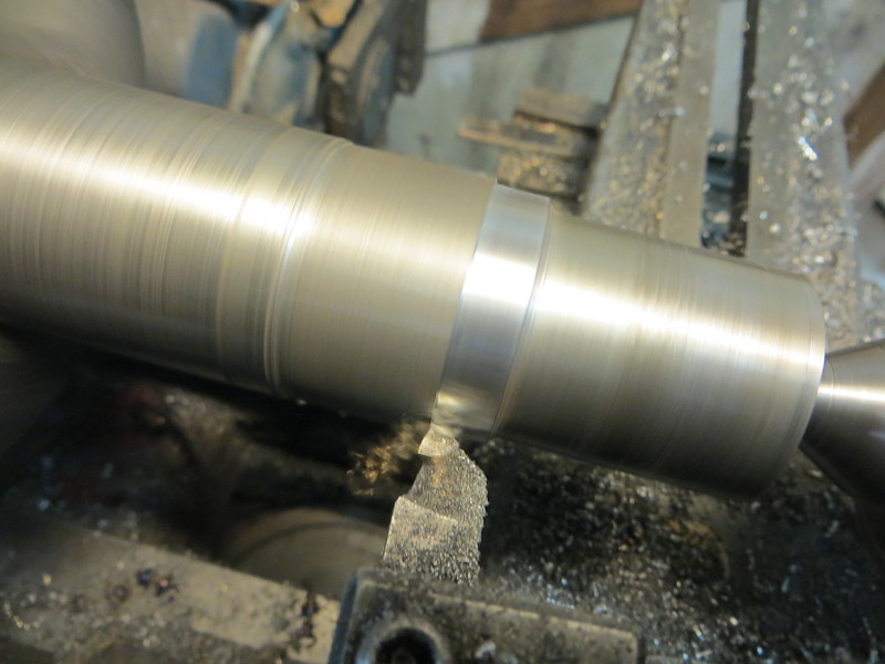
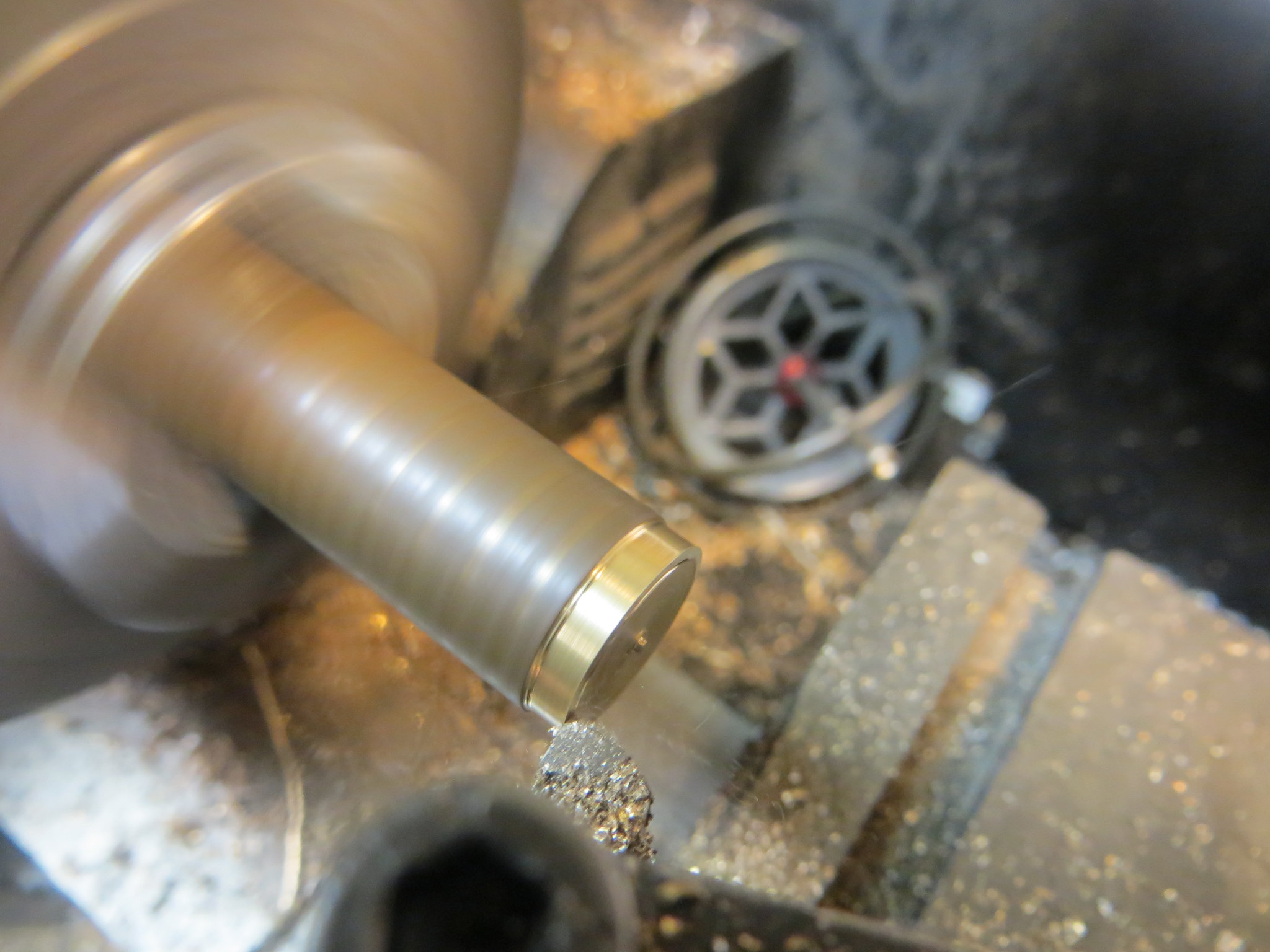
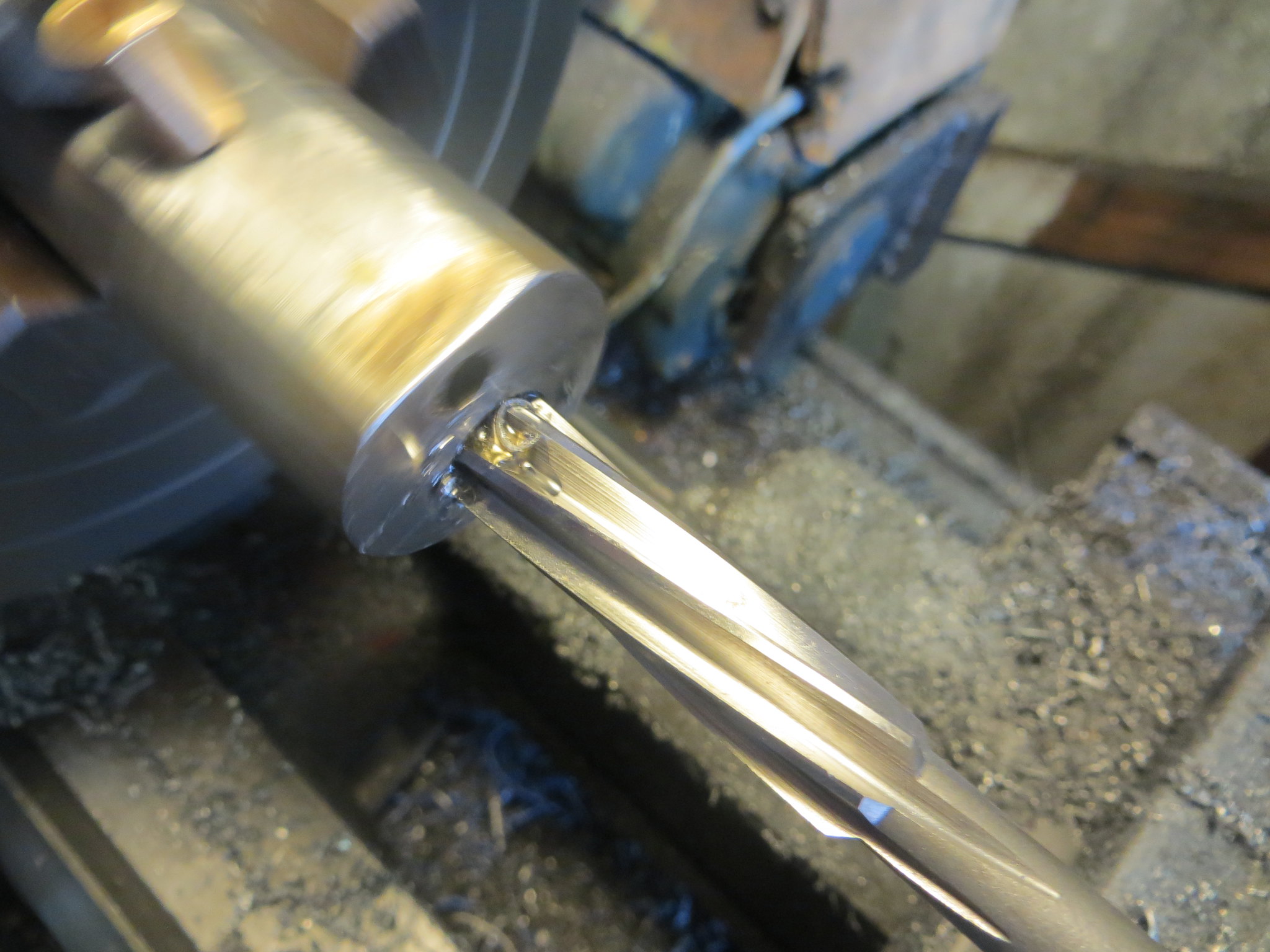
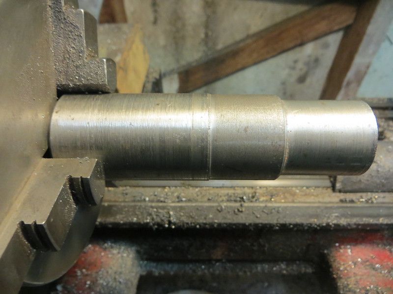
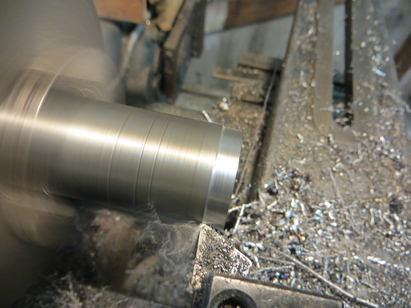
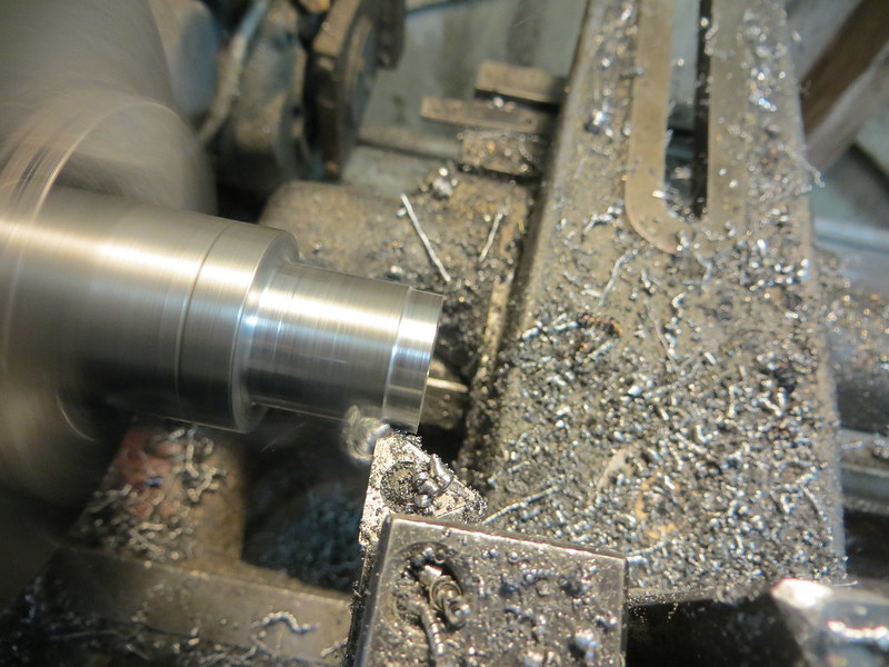
The stock was turned down to the diameter required to accommodate the machining of the eccentric itself plus a little extra for good measure.
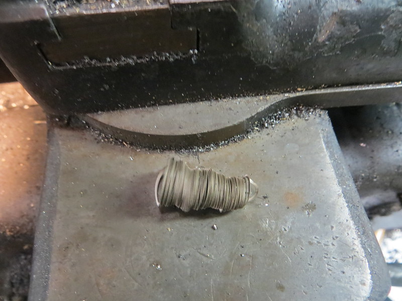
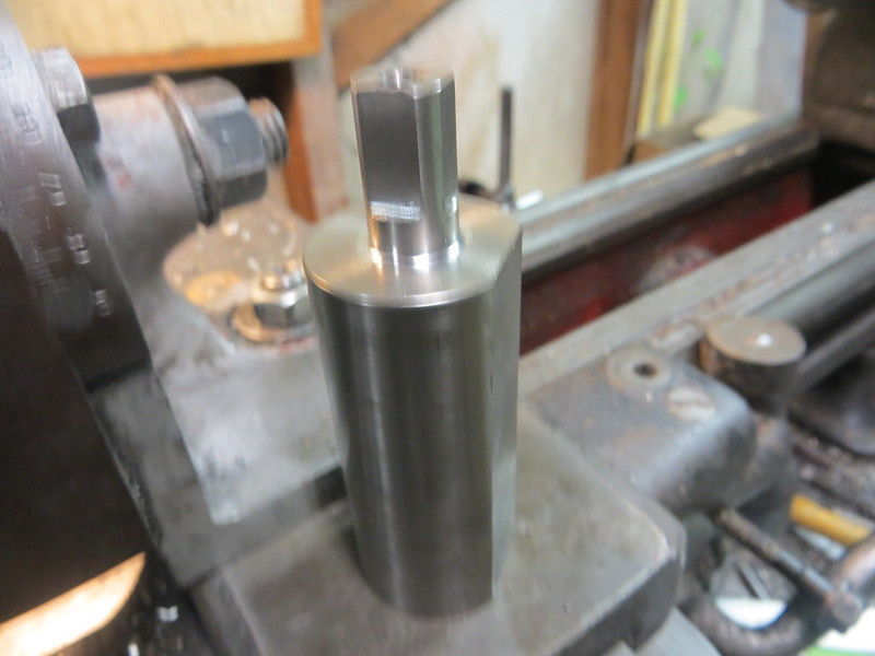
Temporary witness marks were made to indicate the lengths of the various features.
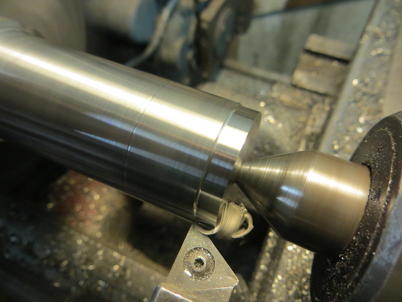
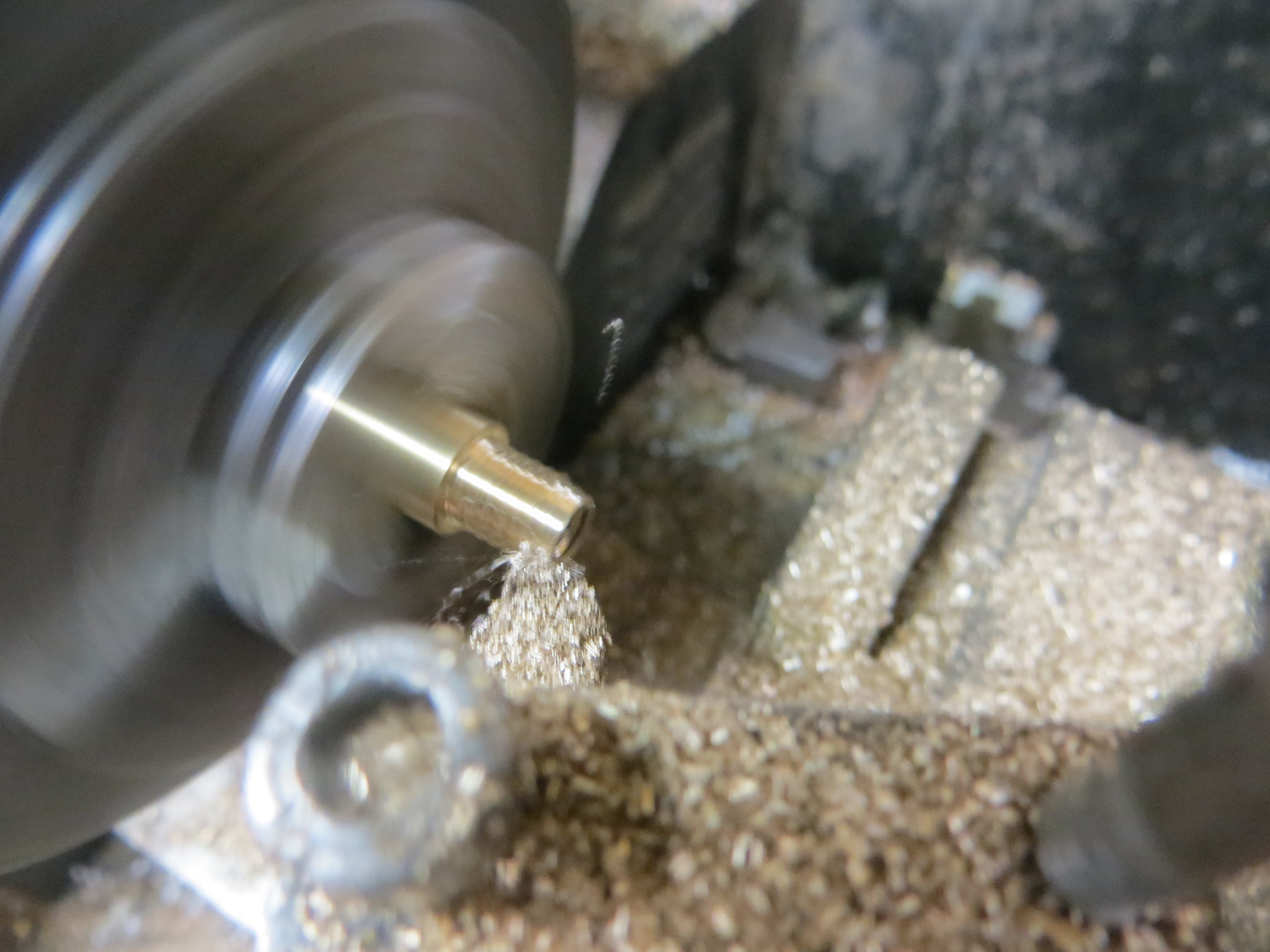
At this point the stock was parted off.
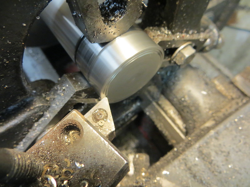
Facing the parted end.
I also took another facing cut on the other end to get a better finish.
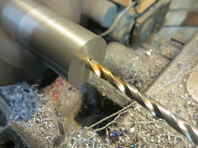

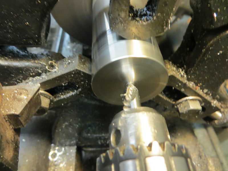
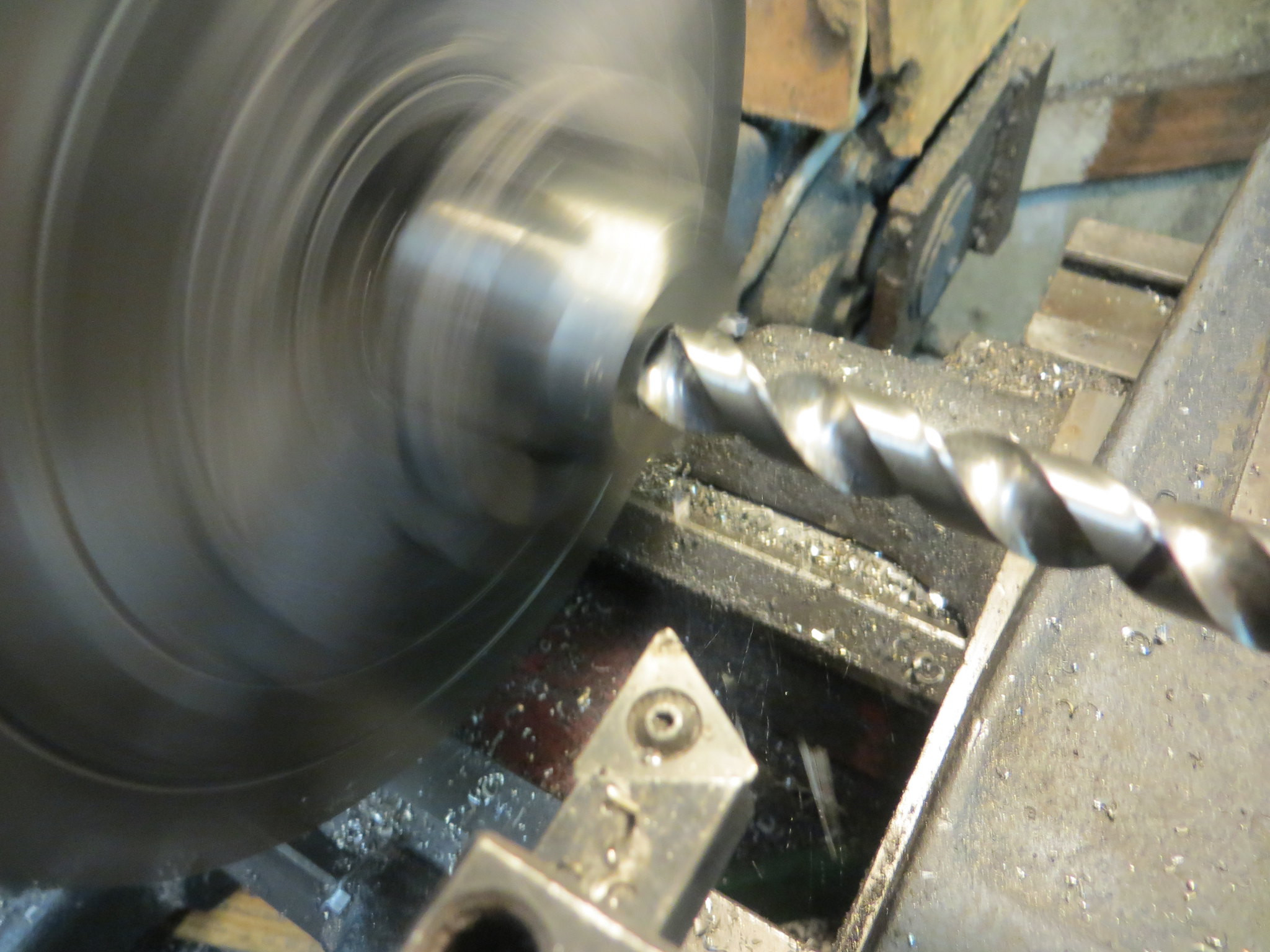
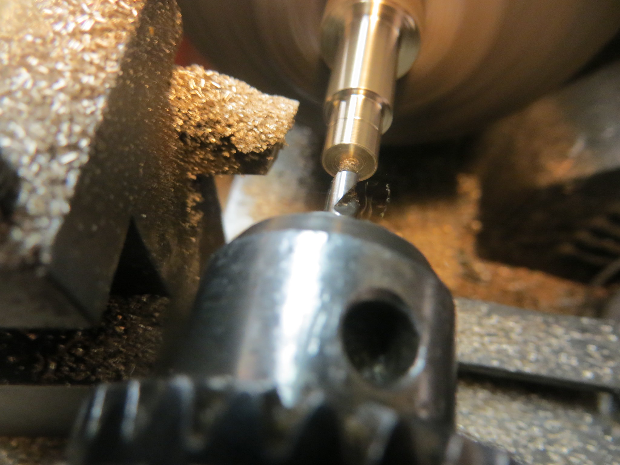
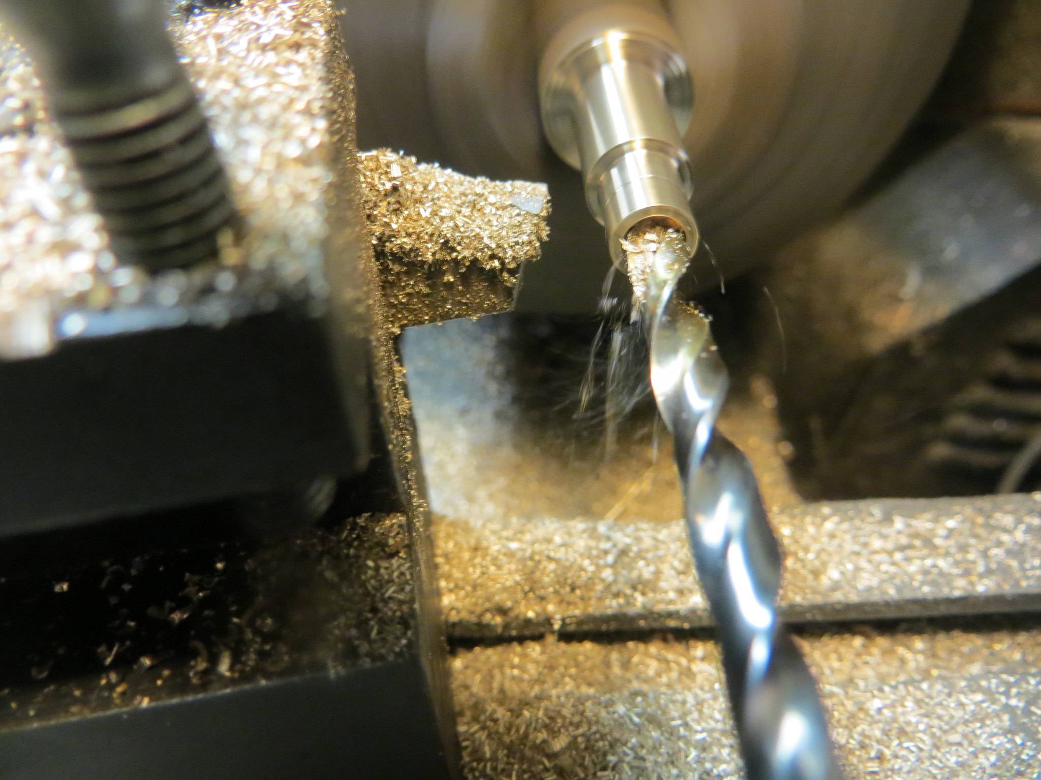
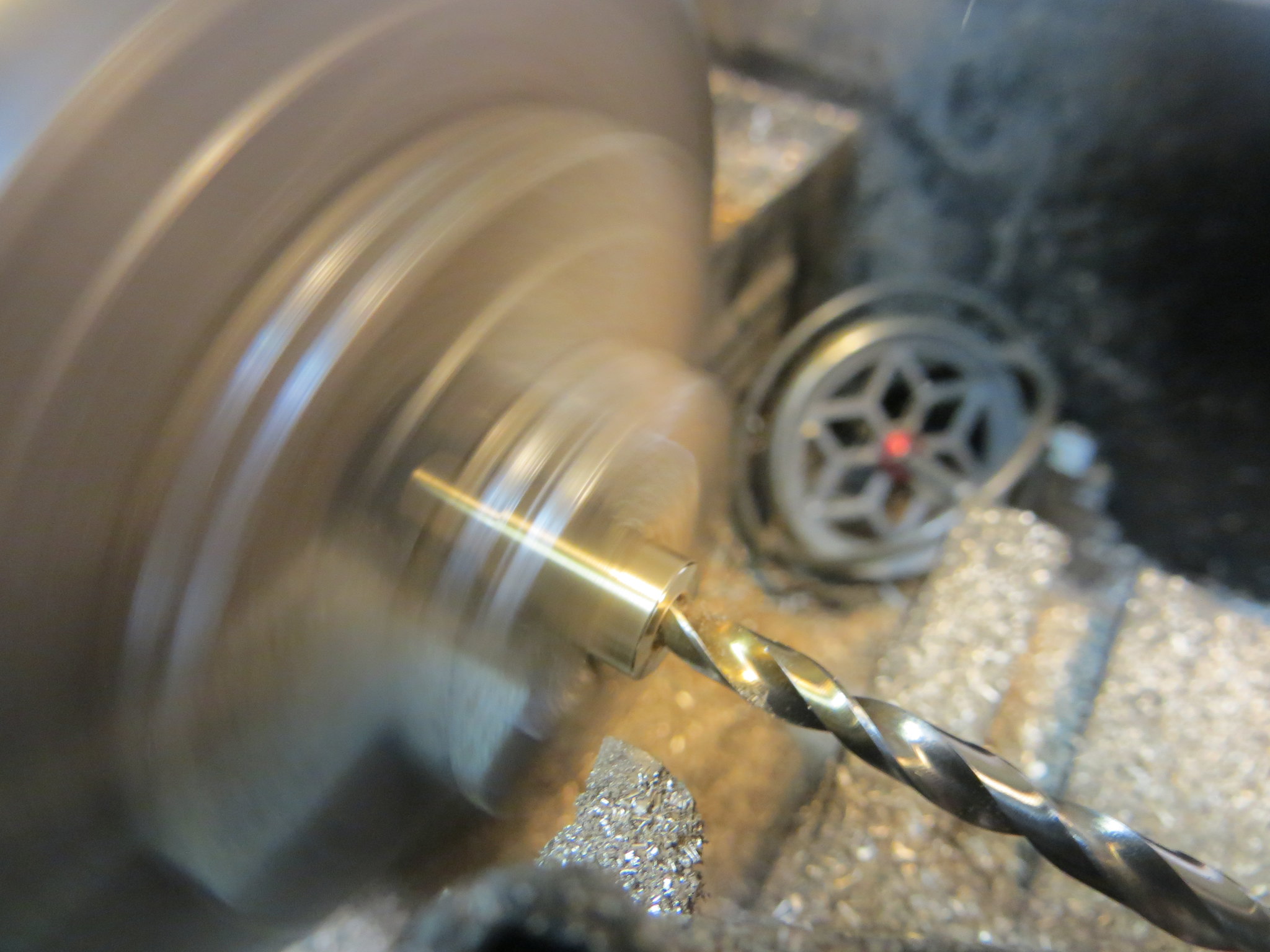
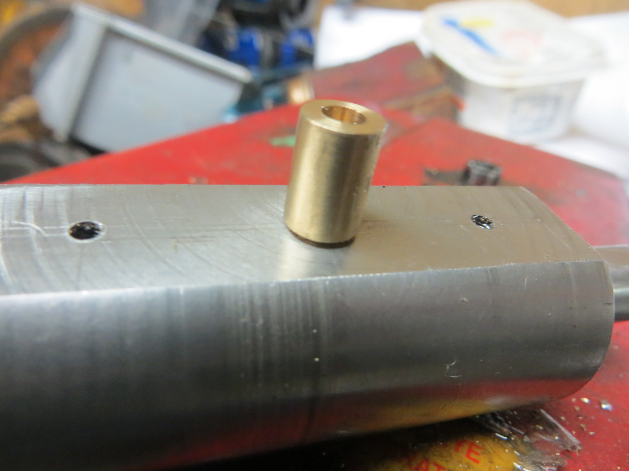
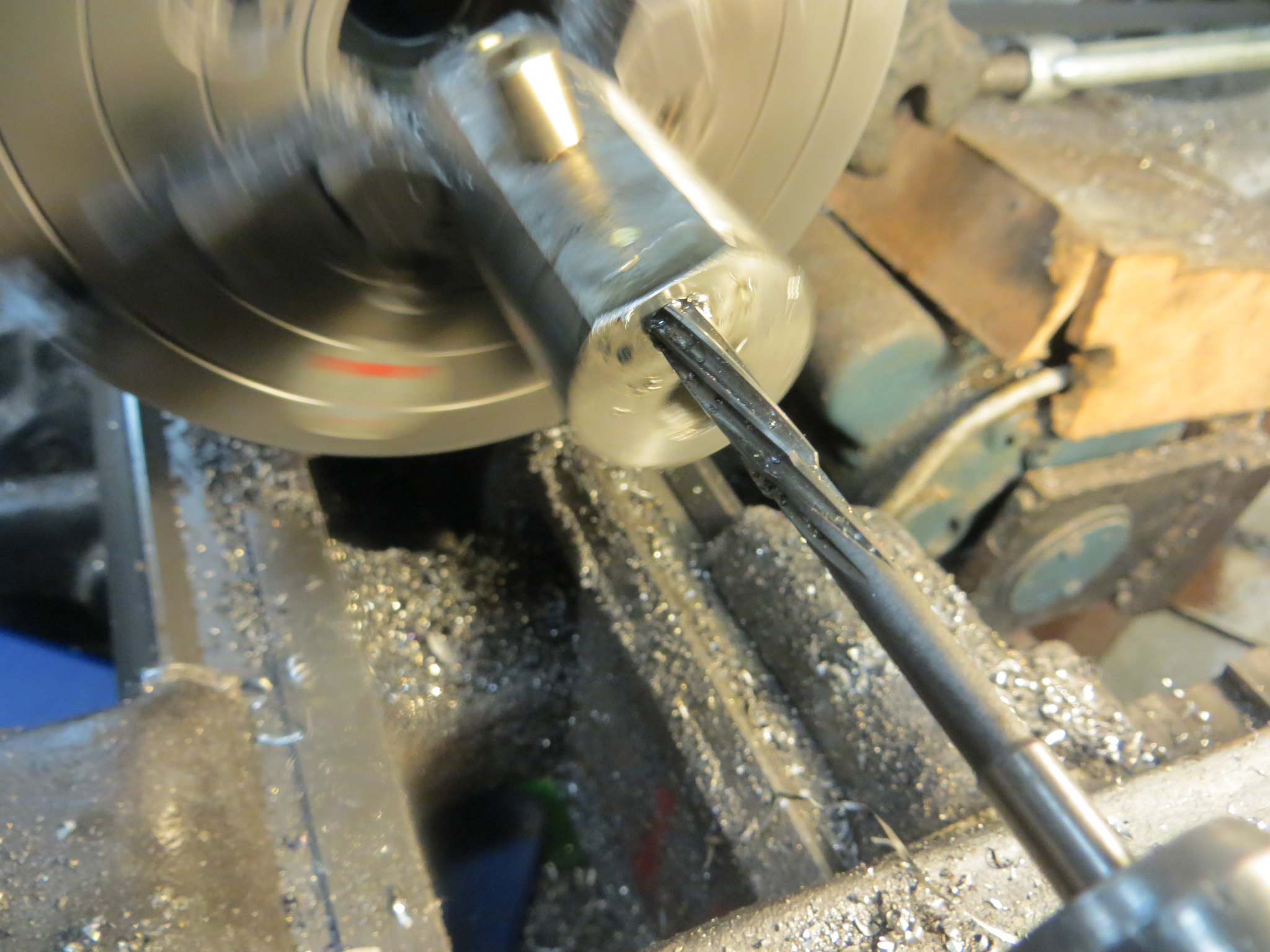
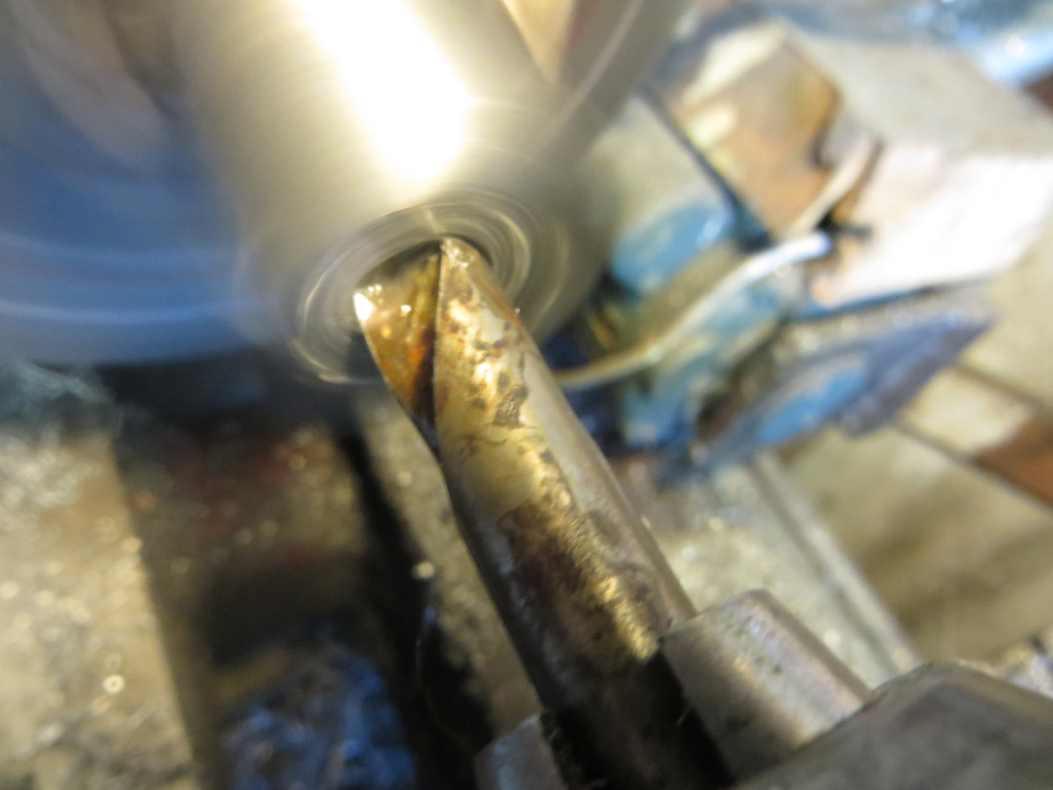
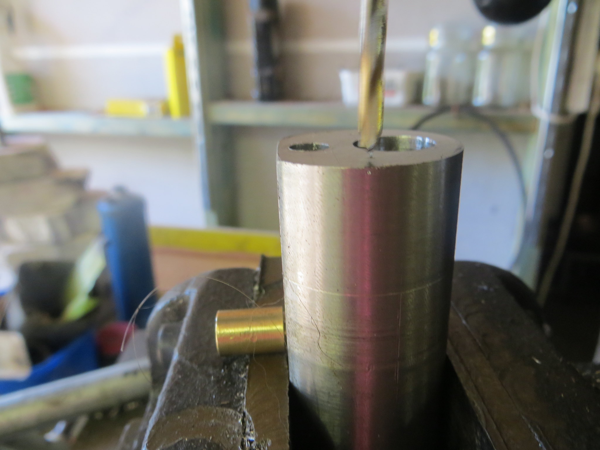
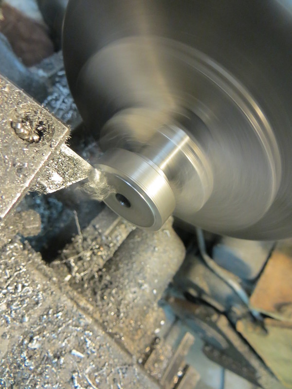
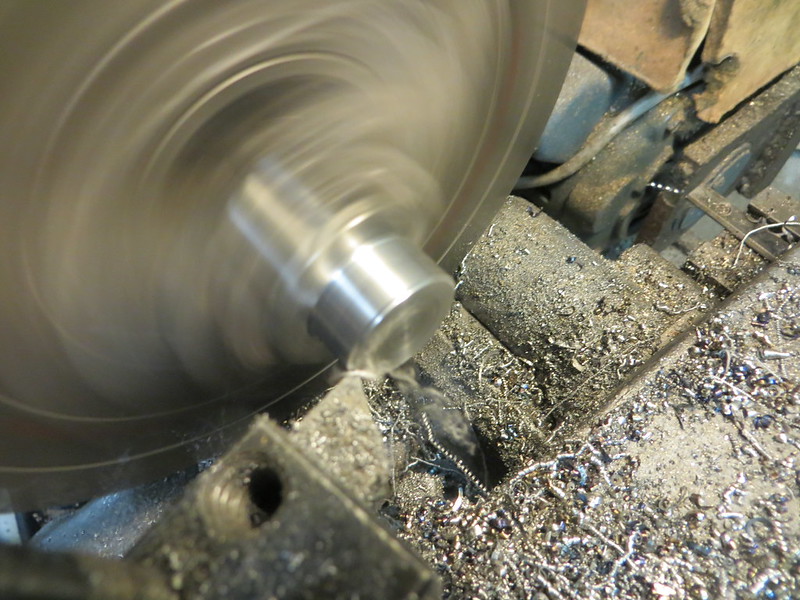
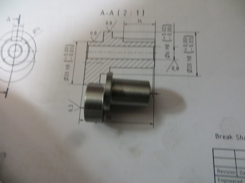
The eccentric, which also has a concentric section where the flywheel/pulley mounts, requires a 6mm hole all the way through. However the tolerance for this hole is plus 0.02, minus nothing, which means that it had to be drilled undersize and reamed.
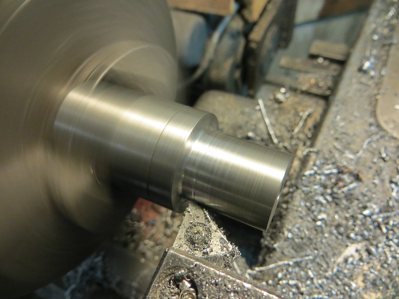
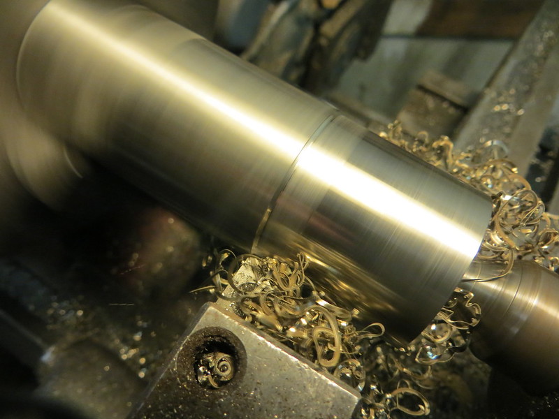
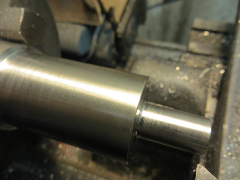
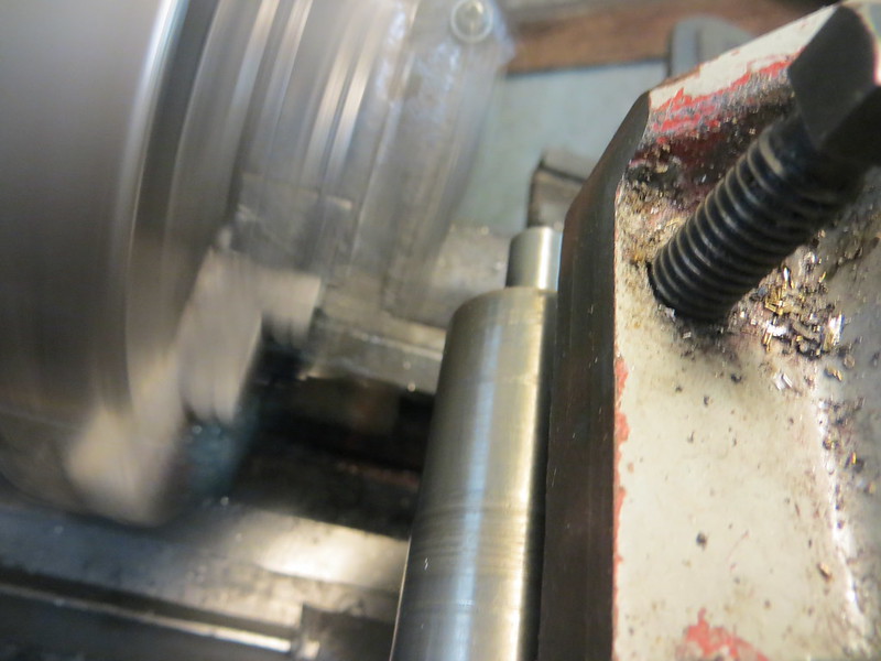
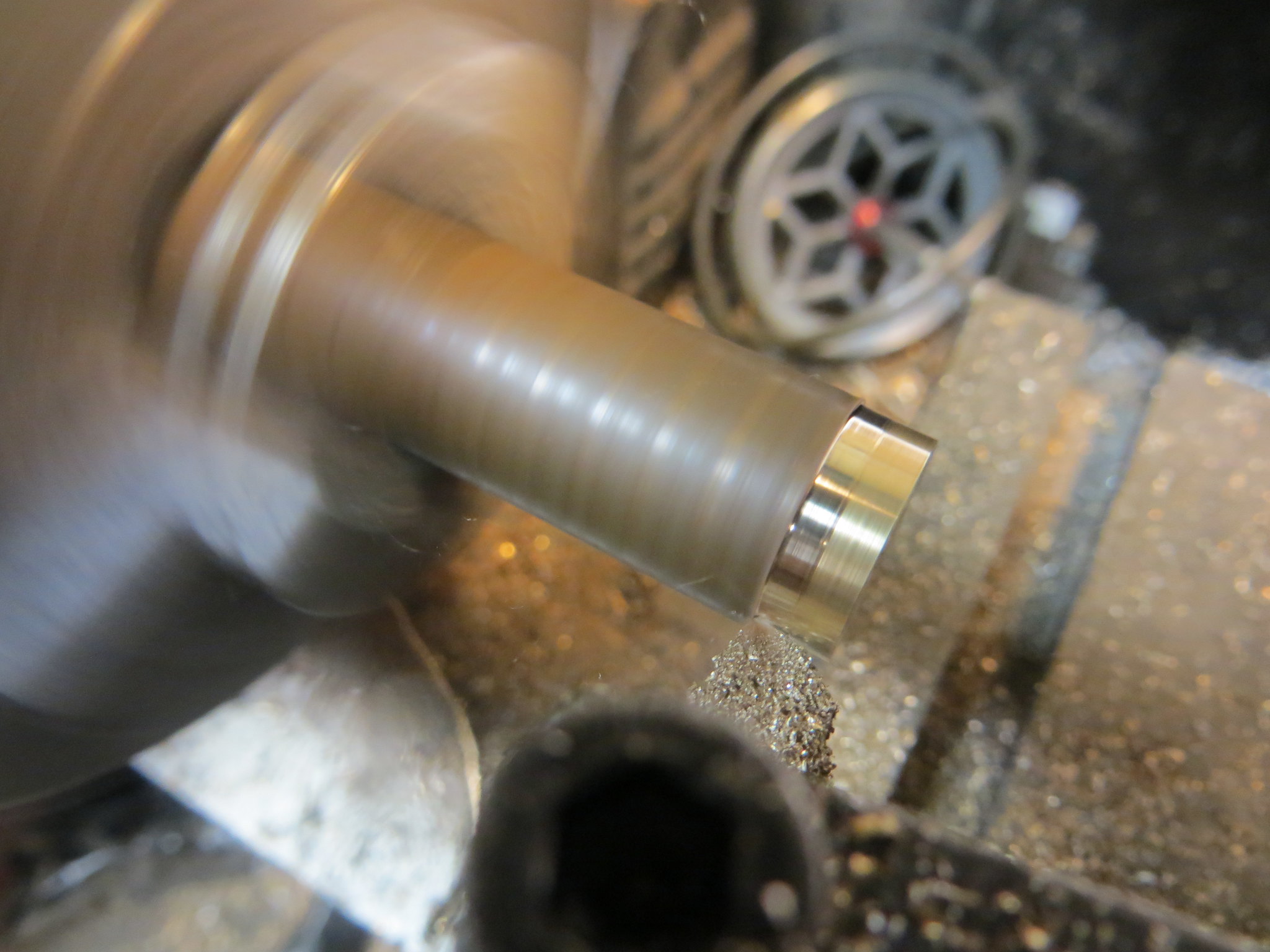
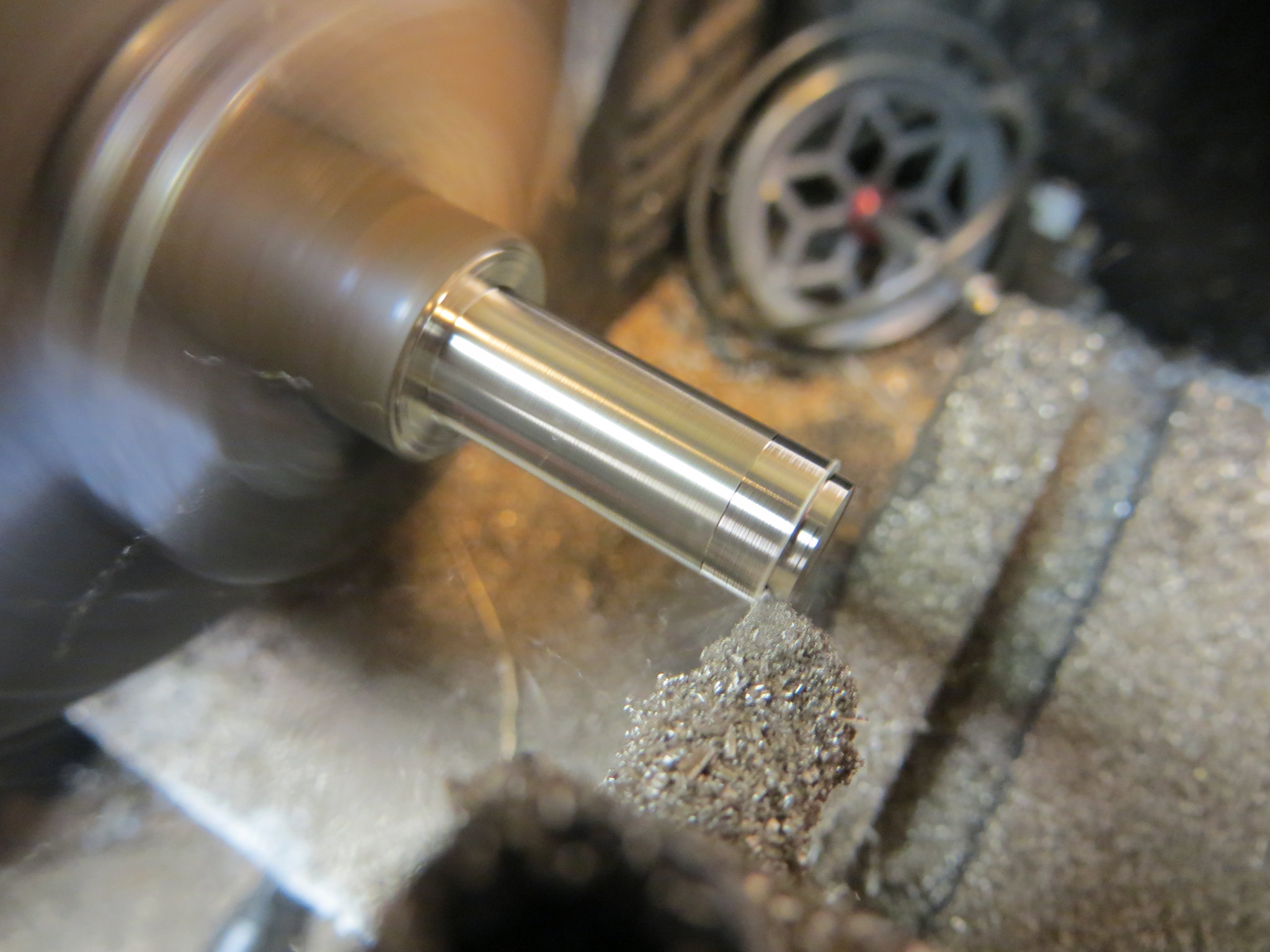
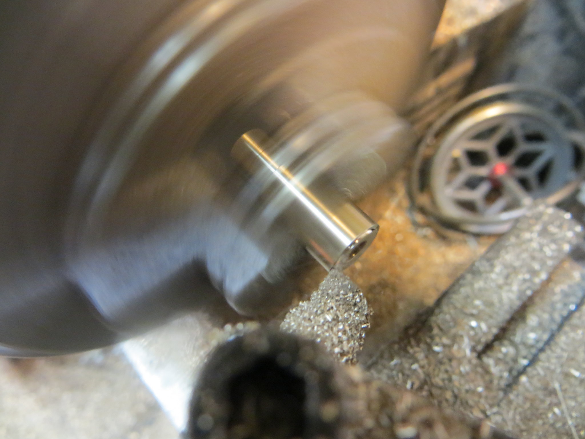
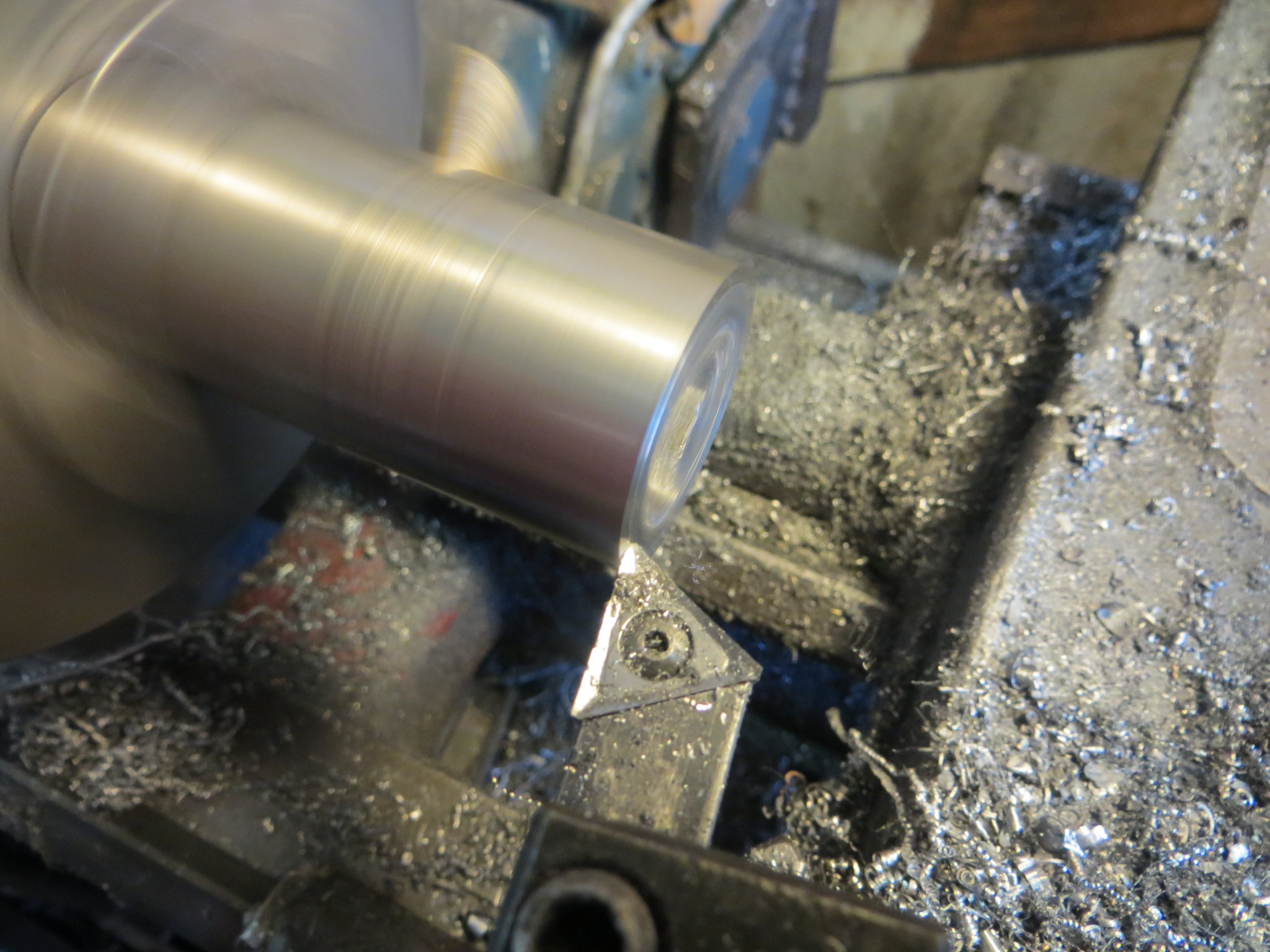
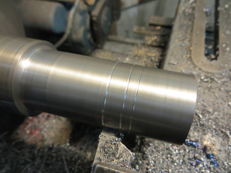
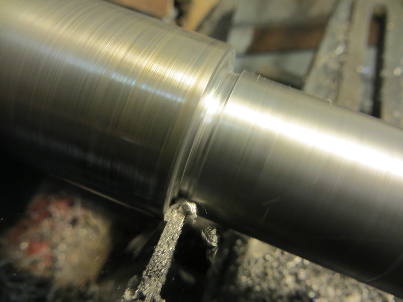
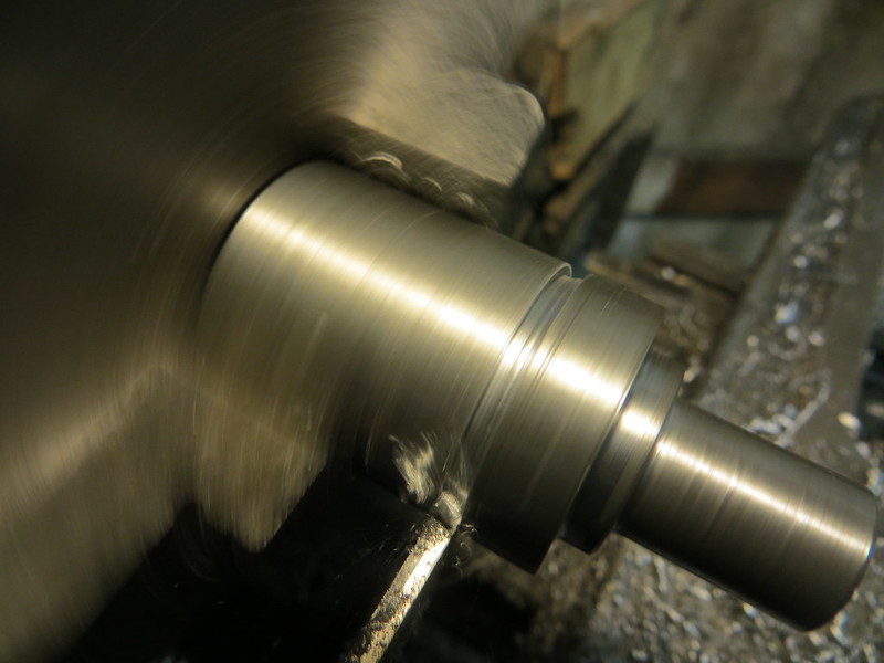
Turning the two concentric diameters, 20mm and 14mm.
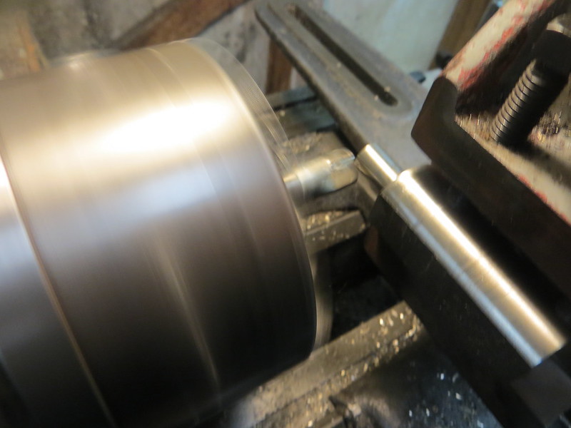
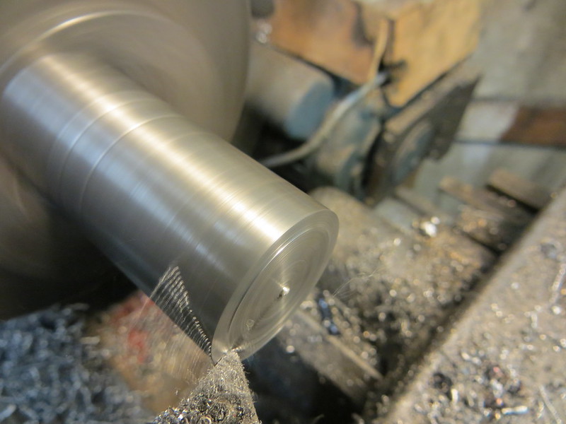
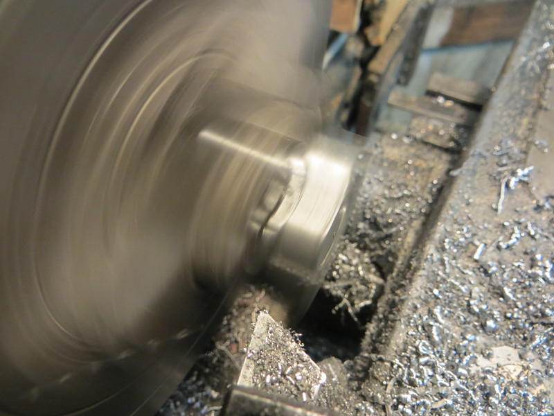
Parting off the part-finished eccentric.
Facing to length.
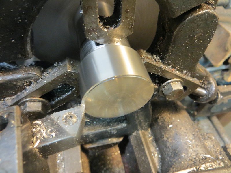
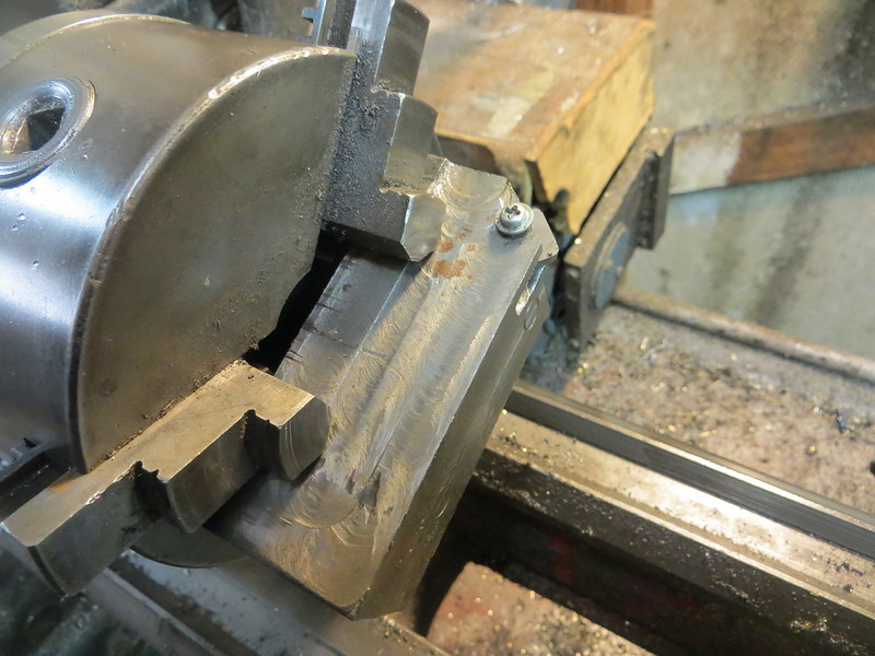
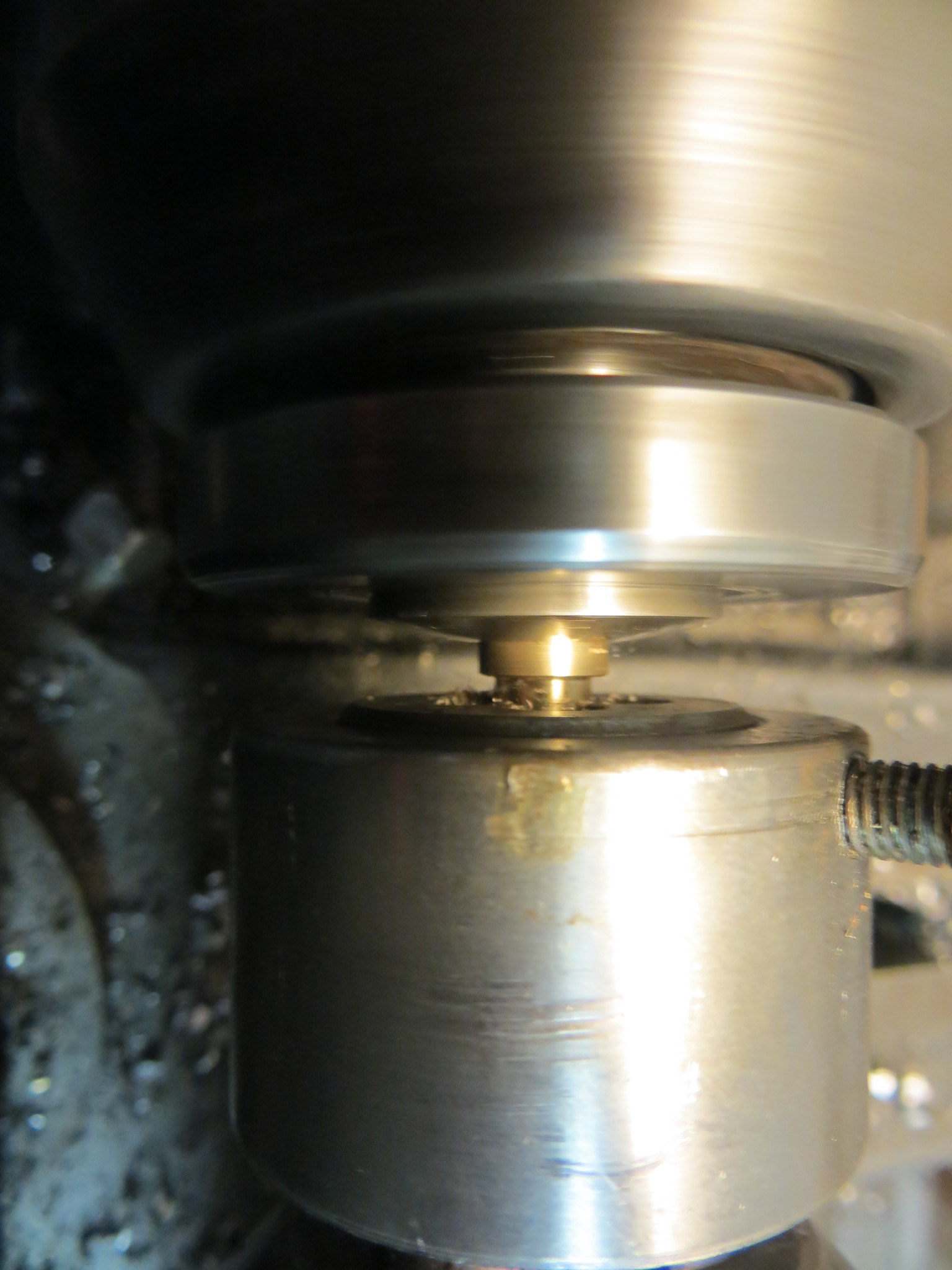
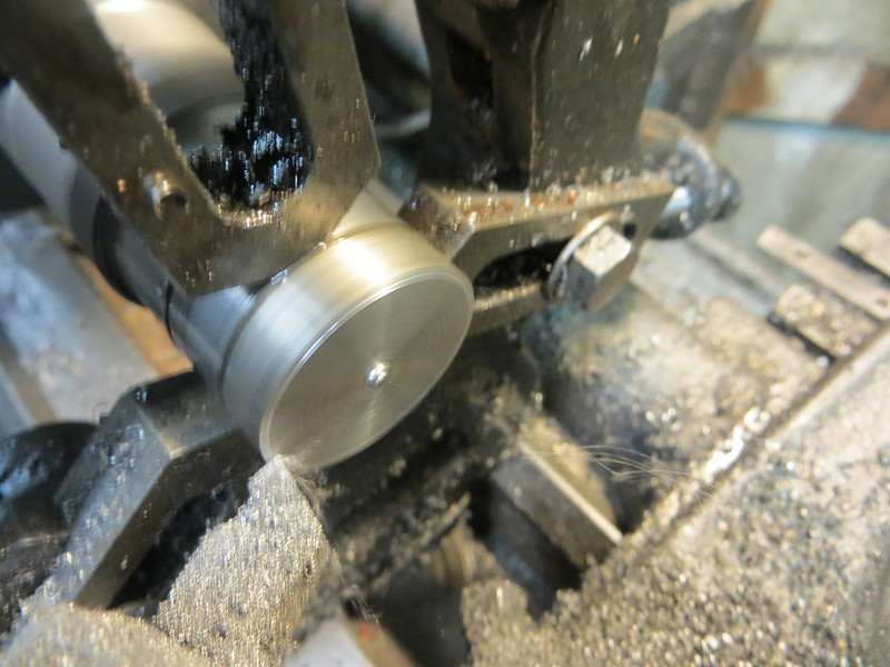
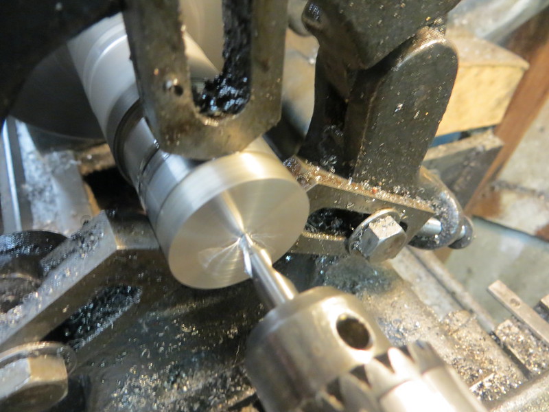
To turn the actual eccentric in the strict sense, the job was set up offset in the 4-jaw chuck. The way I typically do this is to make a center punch mark where I want the axis of rotation to be, and then dial this in using a dead center held against it by a live center in the tailstock.
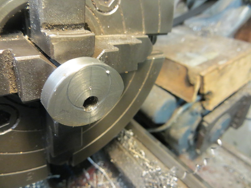
The first attempt at this literally went pear-shaped since I didn't leake enough stock on it. The circular scratch shows what I wanted to end up with. :fan:
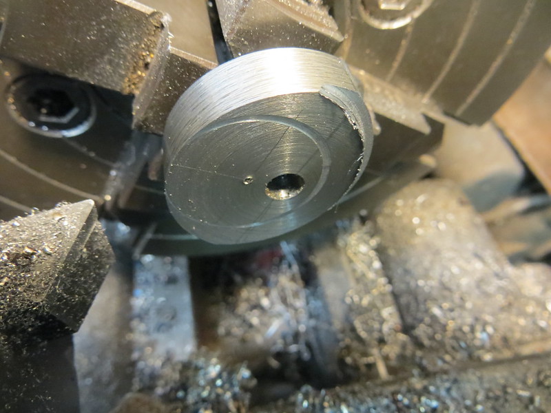
Fortunately, everything went to plan the second time around.
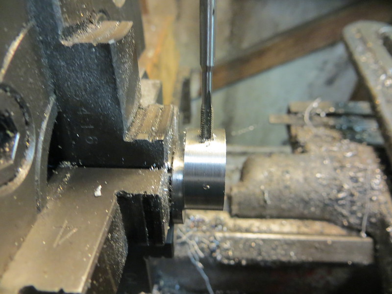
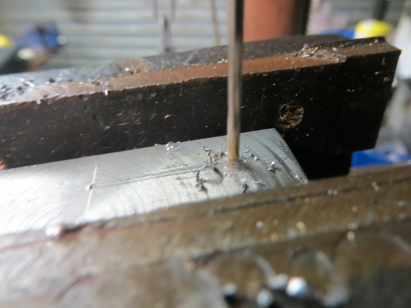
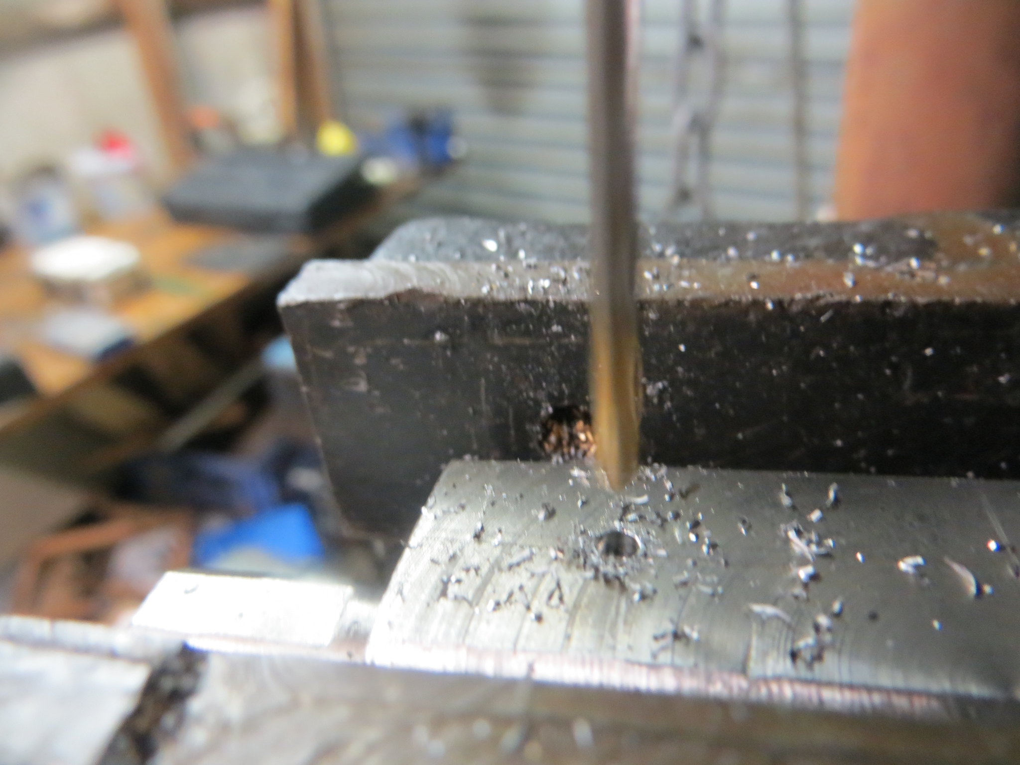
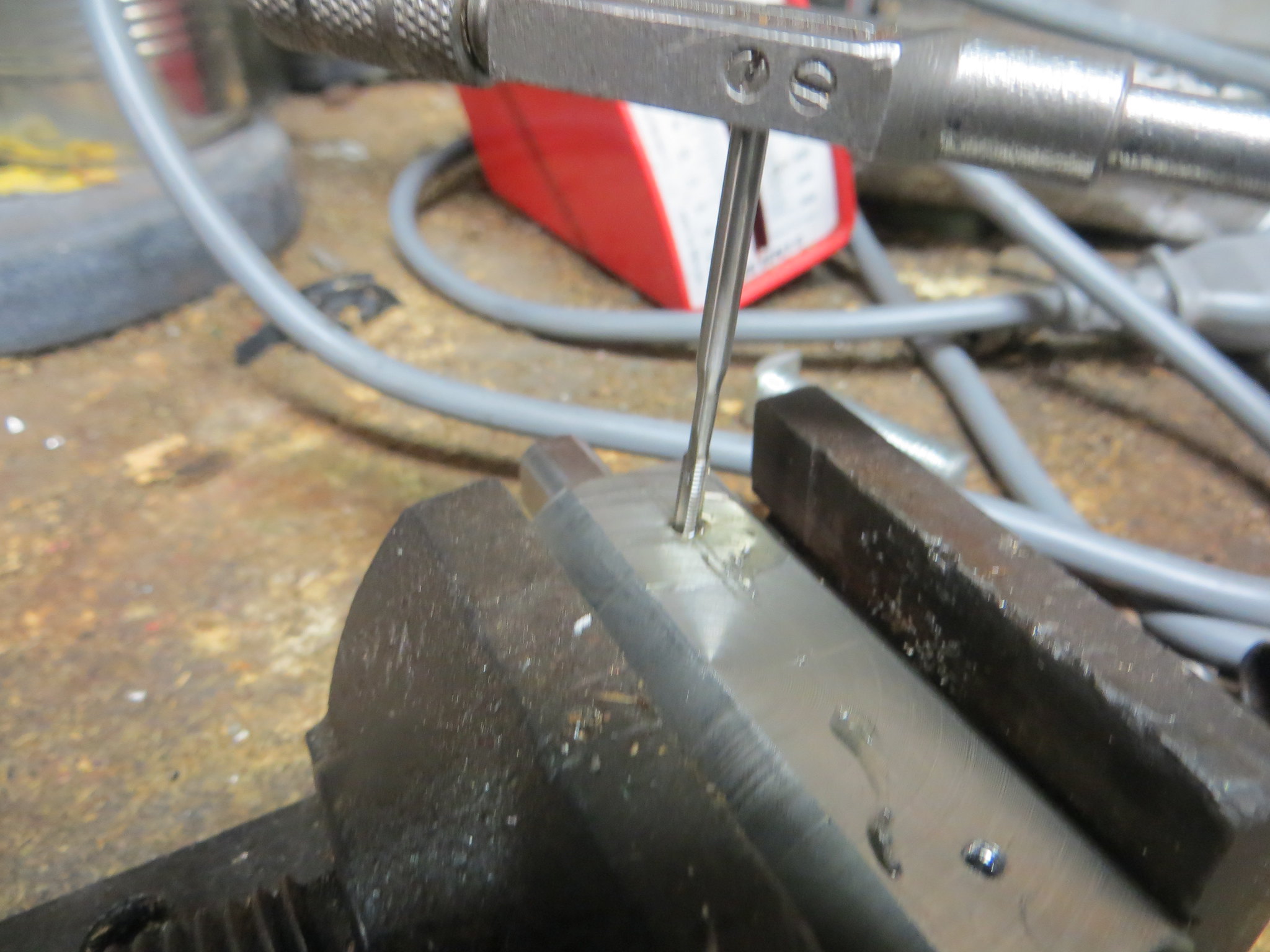
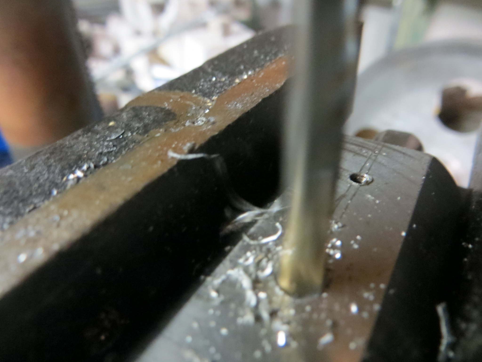
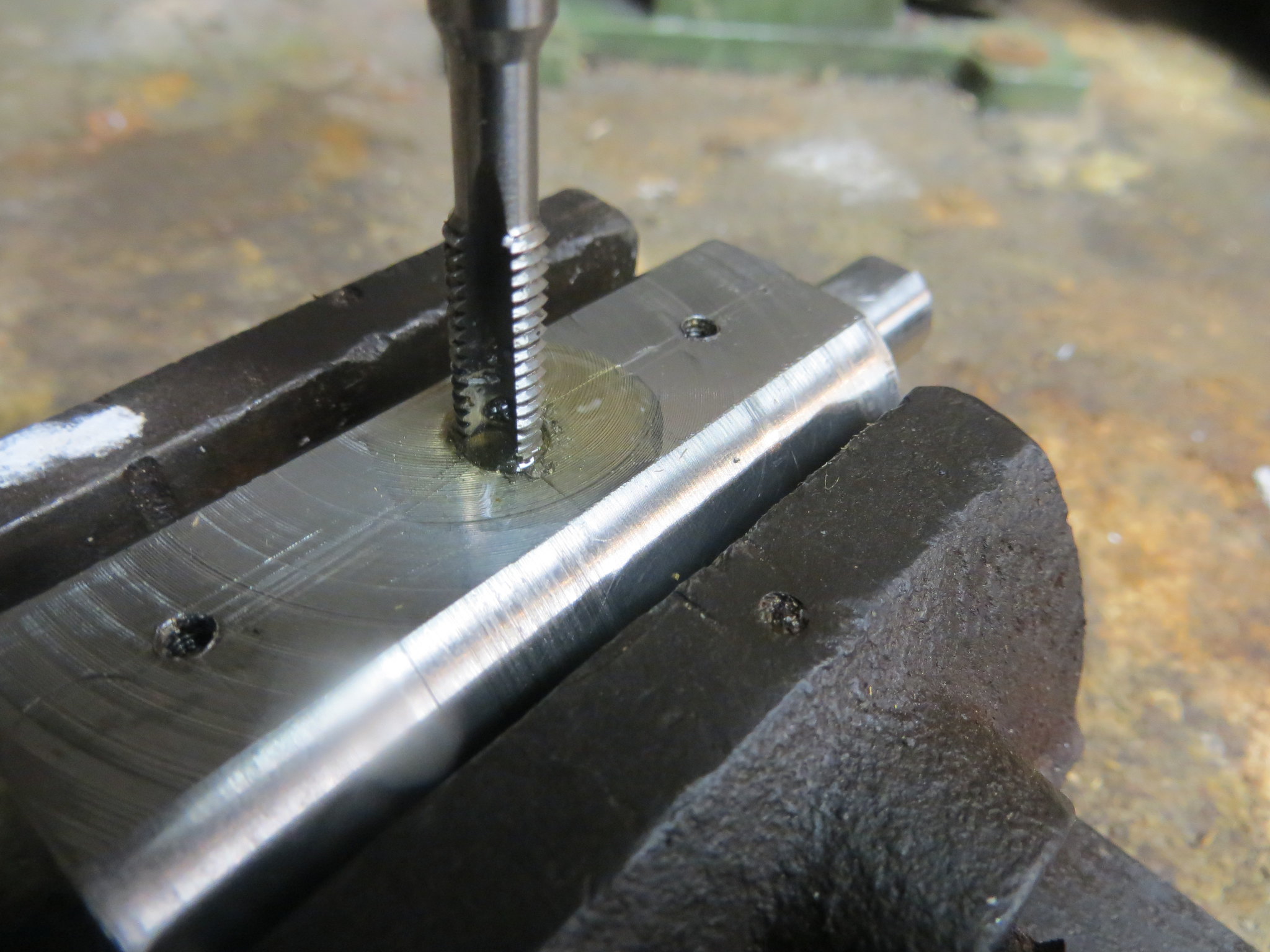
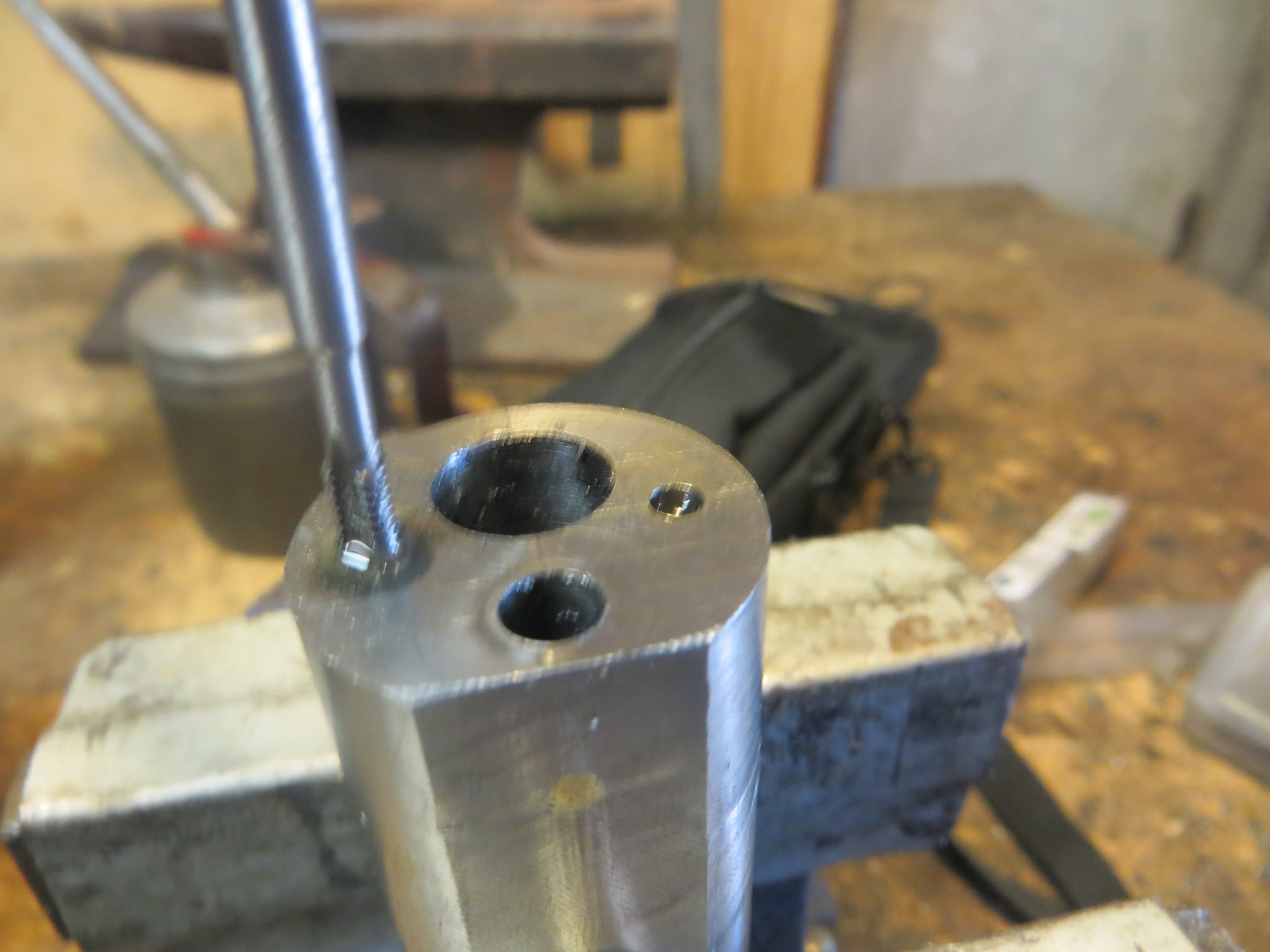
One key change I made on this part was to drill and tap a hole for a grubscrew, which will allow me to adjust the timing, and will also reduce the risk of the eccentric slipping out of time when the engine is running. The plans also called for the flywheel to be keyed in place, which I don't think is really necessary on an engine this size, a grubscrew or two will do nicely.
Finish facing.
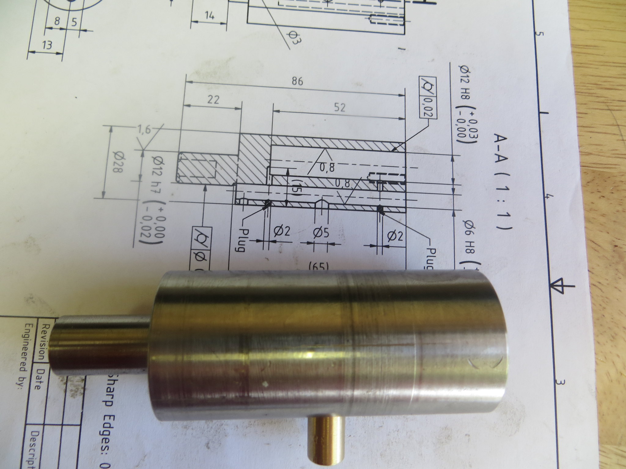
The finished part.
Here's a rendering of a CAD model of this engine made by a man named Jerry Koontz. I included it here to give an idea of what the finished engine should look like.
I am making some slight changes here and there to suit how I would do things.
I decided to start with the eccentric. In the original plans Jurgen has specified white acetal resin for this part, but I decided to make it from this piece of steel since I believe it will wear better, will not be affected by heat when the engine is run on steam, and besides, I have more mild steel kicking about than I know what to do with!
With the steady rest used to provide adequate support the work is faced and center drilled.
The stock was turned down to the diameter required to accommodate the machining of the eccentric itself plus a little extra for good measure.
Temporary witness marks were made to indicate the lengths of the various features.
At this point the stock was parted off.
Facing the parted end.
I also took another facing cut on the other end to get a better finish.
The eccentric, which also has a concentric section where the flywheel/pulley mounts, requires a 6mm hole all the way through. However the tolerance for this hole is plus 0.02, minus nothing, which means that it had to be drilled undersize and reamed.
Turning the two concentric diameters, 20mm and 14mm.
Parting off the part-finished eccentric.
Facing to length.
To turn the actual eccentric in the strict sense, the job was set up offset in the 4-jaw chuck. The way I typically do this is to make a center punch mark where I want the axis of rotation to be, and then dial this in using a dead center held against it by a live center in the tailstock.
The first attempt at this literally went pear-shaped since I didn't leake enough stock on it. The circular scratch shows what I wanted to end up with. :fan:
Fortunately, everything went to plan the second time around.
One key change I made on this part was to drill and tap a hole for a grubscrew, which will allow me to adjust the timing, and will also reduce the risk of the eccentric slipping out of time when the engine is running. The plans also called for the flywheel to be keyed in place, which I don't think is really necessary on an engine this size, a grubscrew or two will do nicely.
Finish facing.
The finished part.