My Little Donkey

Home Model Engine Machinist Forum

Help Support Home Model Engine Machinist Forum:

This site may earn a commission from merchant affiliate links, including eBay, Amazon, and others.

Jasonb

Project of the Month Winner!!!
Project of the Month Winner
Joined
Mar 30, 2008
Messages
3,760
Reaction score
1,239
Location
Surrey, UK
As I showed some of the design stages of this engine that I have just finished in the "3D cad Sequence" thread I thought I should post a couple of images and a video here

I first saw one of these engines on e-bay 3-4 years ago, liked the look of it so copied the images to my "Future Projects" file though I did not know exactly what it was. Over the years a couple more have cropped up on the same site and one of those included a copy of a page from an early Bassett-Lowke catalogue which gave a couple of sizes as well as a description

pump_add.JPG


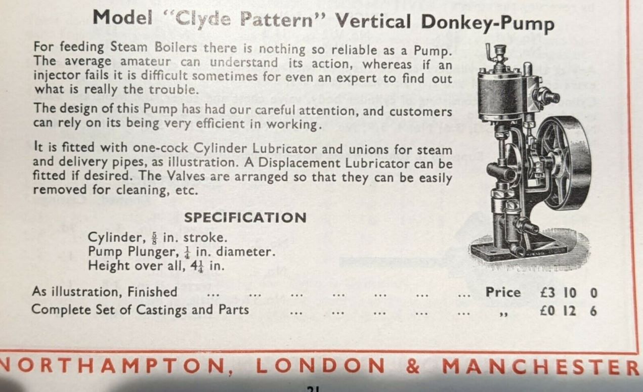
Using one of the photos that had a reasonably square on side shot I imported the image into Alibre and scaled it to suit. I could then take sizes off of that to produce a replica, this time in metric and I kept it about the same size with a 16mm bore and 15mm stroke.

pumper_3D.JPG


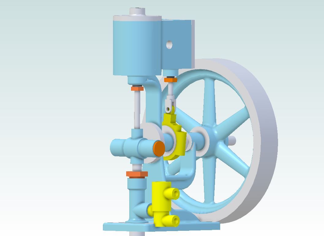
It was done using a mixture of silver soldered fabrications and cutting from solid. Mostly on the manual machines though I did use the CNC to cut a couple of parts that form the frame and also do the flywheel from a slice of 80mm CI bar.

It's the first engine I've done with a Scotch Yoke so that's another notch on the workshop door frame. Seems to run quite well on a few psi and even pumps though I think some house training is in order.

 
Great work!
Was this the first (engine) design you've done in metric? I know you designed a lot of engines with your "standard" imperial bore/stroke combo.

John
 
John I've about 20 engines now that I have designed either from old image or reworked/scaled from old plans, all designed in metric and my "standard" bore is 24mm mostly as its an economic size to make pistons from as there is little waste if you use either metric 25mm stock or imperial 1"

Pat, I guess I just have a good eye and I did it with plenty of constraints and dimensions:) It's actually one I drew for the previous small engine which was a rare Stuart offering from the 30s that used their "progress" flywheel. Did not fancy paying £24 for a casting so drew one up that looked good to my eve with the correct overall sizes and v=cut from a £3 slice of cast iron bar. I liked the way it came out so just scaled it up in Alibre and ran a larger 80mm version off on the CNC
 
Pat, I guess I just have a good eye and I did it with plenty of constraints and dimensions
LOL
Well it looks good in spite of that.

But seriously, lots of folks make a great looking engine, and put a wonky looking flywheel on it.
The flywheel makes the engine in my opinion.
This one looks great.

.
 
Last edited:
Even a good looking flywheel can be wonky if there is a bit too much slack between the hub hole and shaft. It's also a hell of a lot quicker and easier to get the shaping done on the CNC than with manual machines which is why I often bought in flywheel castings when I first started doing my own designs.

Talking of design and coming back the the 24mm bore that I mentioned I use quite a lot, apart from the practicalities of machining it is a good number in a couple of other ways.

When I enlarge or reduce an old design which will more than likely be in imperial then 24mm works out well for engines with 3/4" or 1 1/2".

In the case of the smaller 3/4" bore if I want to enlarge the engine then 3/4" is the same as 24/32" which makes for easy conversion without having to take your socks off as every 1/32" on he drawing equates to 1mm on the new design so you keep most things to full 1mm increments.

Similar when I'm reducing a 1 1/2" bore engine down in size as that measurement can be expressed as 24/16" so 16" on the original equates to 1mm on the new design.

But what about an engine that originally had a 1" bore.

I could simply do a direct conversion and use a bore of 25.4mm but to me you are not really producing a metric design you are just converting numbers and will end up using say a 1/4" reamer and not a 6.35mm reamer. This can also be a problem if you model something full size and then simply apply a scaling factor to it, you can end up with some non nominal sizes quite soon on that 1/3rd scale model.

Some may use 25mm as the bore which would be a reasonable nearest nominal size to use but then if keeping proportions the same you soon end up with sizes that have more decimal places than are practical. Lets take that same 1/4" dimension, if kept proportional to the 1" bore you would end up with 6.25mm. Now nobody wants to turn down the next available bar stock to 6.25 or buy a special reamer that size.

However the 24mm bore works out quite well here with most commonly used imperial sizes converting well to metric:

1" =24mm
1/2" =12mm
1/4" =6mm
1/8" = 3mm
1/16" = 1.5mm

The few exceptions are 3/8 which I would generally use 10mm for and 5/16" which 8mm is what I usually use
 
Hi Jason, I find your donkey engine very interesting because I am looking for a design for one for a 5 inch gauge locomotive I am building. There is a shortage of designs for ones that work. LBSC has a design in Shop shed and Road but I wouldn't be very confident that it would work and there is one is Henry Greenly's book but again I've never seen a working model. Do you think you could try pumping water into a boiler with it say at 80psi?
 
That’s a really smooth running engine! The flywheel runs perfectly, and pump looks like it has impressive pressure. I like your “fuzzy” math for imperial to metric conversion while scaling. Many times I’m faced with conversions in the other direction, and I agree, it’s difficult to maintain scale!

Congratulations!
John W
 
Last edited:
I work in imperial.
No doubt there are advantages to metric, especially if you are use to it, but I am tooled for imperial, and so no chance of metric for me.
I think in imperial too, so metric is foreign to me as far as coming natural.

.
 
I'm tooled for both and will make an imperial kit in imperial but given the choice use metric as it's what I was brought up with and what I use for work.
 
John unfortunately I don't have anything to do the test with. I'm not even sure if something like this would work to 80psi as most boilers of the day were only 50psi or so maximum. I was actually in two minds whether to add the valve chamber or just do it with the pump ram, in the end I did quickly make up the brass chamber as I knew people would want to see it pumping and I'm sure some tweaks to ball lift etc would be needed to get it performing at pressure.
 
Ok, thanks Jason. I have another photo of one by LBSC, it's on his 31/2 gauge 2-2-2 Grosvenor in the book 'Shop, Shed and Road'. Unfortuneatly he didn't include any description of it. It's a single cylinder one.
 
Hi I've made many donkey pumps some are on my YouTube videos including the lbsc pump from shop shed and road. Quite fiddly to make and really for a 21/2 inch guage loco, yes it does work. Another twin cylinder freely available on the internet is a van brocklin design fitted to my 5" Shay loco.
I have other non copyright drawings .
Brian

https://youtube.com/user/Toolsaddo
 
re #12: I think the key is that on a real boiler, the steam pressure is the same as the pumped water pressure - to get the clack to open. As the steam piston is usually 3 x (or more) than the water pump piston in AREA, this works fine. Just a matter of the piston seal (leak-back) of the water-pump piston. Once primed, the pump should work well, I think? (I have made a nicely working feed-pump for a boiler of my steam launch - necessary as I can't reach the middle of the pond to use a hand-pump!).
Jason, this is a very nice design, especially as it has the scotch yoke. But there are many designs that are purely linear - with "knock-over" valves for the steam side. I last saw a row of these used for transferring fuel from storage tank to mixer tank etc. in an oil blending and mixing plant.

https://johnsmachines.com/2019/08/20/steam-powered-water-feed-pump/K2
 
It was the look of the engine/pump that caught my eye as it is nicely proportioned and having the pump and it's scotch yoke is an added attraction.

I did do another pump a few years back that has the "banjo" type arrangement to allow the crank to clear the piston rod / pump ram assembly. Bit bigger this one at 16" tall and an 8" flywheel, I've only tried it blowing up latex gloved held over the pump outlet. All scratch built except the flywheel which was a casting.

 
Back
Top