My First Glow Plug Engine

Home Model Engine Machinist Forum

Help Support Home Model Engine Machinist Forum:

This site may earn a commission from merchant affiliate links, including eBay, Amazon, and others.
The alloy for the block is not too critical, just the HE15 for the conrod.

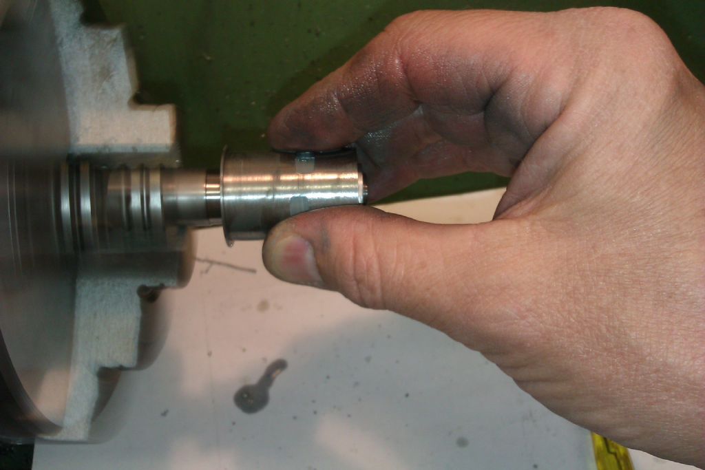
You could drill most of the nipple larger and just the end 1.0mm

J

That's exactly what I did.Gus been breaking 0.5----1.0 mm drill bits until he got to sly,cunning and smart.Ha Ha. The fuel nipple was so exotic,just cannot send it to the scrap pile.

Thanks for the kind advice. Will take sweet time to finish up the engine.

Best regards ,Gus.
 
After a nail biting 2 hour session,got the transfer/exhaust ports millled.Ports are in alignment with barrel cylinder.
Nothing went to the scrap bin.Will move on the evening to make Jason-b's adjustable cylinder honing tool.
Have scrutinised other honing tool but none as sure-fired as Jason's.
Jason help. The honing sleeve .Is it made of aluminium???

IMG_0672.jpg
 
Thanks. Got it. The grooves for easy expansion and the sleeve split.

Thanks again Guru.

Picking up the lapping paste tomorrow.Make the honing tool.All this hard work to get the engine
up and running first time.
 
My Cheapy DIY cylinder honing tool done. Happy with initial honing finish and went on to "Colgate" for final hone.
Sorry.I have no "Sunnen" Honing Machine so no cross hatch hone finishing.

The Die threading was done with "Tapmatic" Tapping Oil and thread finishing was good smooth thread.

Thanks You. Jason for the expert advise. Used Aluminium bar to make adjustable hone head.

Also plan to make a piston hone device.Got this from "AMI" UK Magazine December 2008.Will post foto.

See fotos.

IMG_0673.jpg


IMG_0678.jpg


IMG_0686.jpg
 
good stuff...I like that hone design a lot better than mine. Do you hold it by hand or in the tailstock?
 
Lap held in the lathe chuck and hold the liner by hand, that way you don't distort the liner with the chuck jaws.

355362.jpg


J
 
yesh that's hard on the fingers! I'd previously been making a fake cylinder that slides over it (not the full length just the top 1/4 or so) and a fake cylinder head to clamp the rim out of some 1.5" square bar. This time I just lapped when the cylinder was in the boring setup, then did everything else after
 
actually now that I think about it, why not use the actual real cylinder, and clamp it in with a fake cylinder head with a big hole in it? that way any distortion from clamping forces gets honed out.
 
actually now that I think about it, why not use the actual real cylinder, and clamp it in with a fake cylinder head with a big hole in it? that way any distortion from clamping forces gets honed out.

I have heard of something like this, way back in the old days when I was into big performance V8's. The top speed shops would torque down large slabs of steel to the correct tension in place of the heads, then bore/hone the cylinders (through the bottom I assume). Supposedly their is some slight distortion of the block when the heads are on, so this ensured perfectly round bores when the engine was assembled.

I'm going to file your suggestion away for future use. Thanks.
 
good stuff...I like that hone design a lot better than mine. Do you hold it by hand or in the tailstock?

Still messing around by hand to get the feel of it.You are right .Its tough on the hands. Will put in the slow spindle speed drive today to chuck clamp cylinder.
 
Lap held in the lathe chuck and hold the liner by hand, that way you don't distort the liner with the chuck jaws.

355362.jpg


J


Thanks.
Will monkey,monkey today.Then go on to cut piston to size plus one thou and hone to fit. Will post good of bad results.Total green horn in honing.

My honing knowhow is all verbal. To the vendors I am the expert. Till today I am still wondering why "Sunnen" Honing Machine is the preferred machine.

Went to China to audit cylinder hone shops.Honing machines were home made.Took a long time to get them to import honing machines.

In India,I saw low speed drills used to drive honing tool.Results not best!!!

Valve lapping was a joke.No body could tell me best flatness they could achieve. Also took me along time to get them to buy Japanese flat lens and
black lights.
 
Last edited:
During my apprentice days,I was known as the"hacksaw monster".I break saw blades.Can never cut straight.

OK.When you have a balcony to site your machineshop.There is no space to put in a mechanical saw and so back
to humble China hacksaw.Did not do too bad with sawing of a piece from stock bar.C.I. is easier to cut than M.S.

Today not a bad day,completed piston to hone both piston and liner.Left behind wee bitty too much on piston O.D. Was tough to fit in cylinder.OK .Cylinder is slightly tapered for good compression.Hand honing is no joke.My hand are blistered.

OK. Expertise seeked. Duralmin is not available. On hand I have Brass/M.S. Square Bars. Please advise best alternative. Plan to keep engine for display or give away after successful startup/spin.

IMG_0688.jpg


IMG_0690.jpg


IMG_0692.jpg


IMG_0694.jpg
 
Hi to all my Gurus,

This is the first time I do real honing and get good results.
From here ,will move to complete the compression engine with honed cylinder and piston.Bolero was started
building in 2008.Chickened out as I have no prior hone experience .See fotos.Looks like i.c.engine population is
growing.

IMG_0698.jpg


IMG_0700.jpg
 
Carburetor Needle Valve Body

Above was small and intricate.Took a good three hours to complete,would have taken longer if slit saw was
not used to cut to size from a 3/4" square bar.The 1.2 diameter fuel passage was drilled carefully with regular
retraction for chip clearance and Tapmatic Oil application.Drill breakage will mean going to scrap bin.
See attached fotos.Valve body with O.S.Needle 24081970 installed and piped.

IMG_0713.jpg


IMG_0714.jpg


IMG_0715.jpg


IMG_0716.jpg


IMG_0723.jpg
 
I made one of those carbs to use on another engine (same displacement). I discovered I could get a lot more RPM out of the engine by increasing the carb throat to 7.5mm but then became picky about needing muffler pressure in the fuel tank. You may want to try a few different sizes if it's an engine to put on a plane.
 
I made one of those carbs to use on another engine (same displacement). I discovered I could get a lot more RPM out of the engine by increasing the carb throat to 7.5mm but then became picky about needing muffler pressure in the fuel tank. You may want to try a few different sizes if it's an engine to put on a plane.


Thanks for the good advice. After successful spin ,engine goes into collection display.Right now its on the printer. Very happpy I got it completed.
Looking backward,Glad I persisted with its too many challenges and skill requirement.Jigs had to be made.Honing tools. Its true measure twice,cut once.
Jotting down diameter reduction after every pass certainly helped avoid getting wrong OD or ID.
The last time I spinned an engine was 50 years ago while in Polytechnic.Will post video of engine spinning,if I get it going.
 
....Cylinder is slightly tapered for good compression..

Hi Gus. Can you elaborate on your tapered honing procedure? I am assuming the top of the sleeve is slightly smaller diameter than bottom so the piston pinches near TDC? So is the sleeve first put on on the tapered hone, then hone chucked, then progressively pull sleeve back towards the tailstock until taper sized (ie tailstock end of hone is larger diameter than headstock end diameter?).

The picture almost looks like you are inserting the sleeve on the hone & pushing into headstock direction. Hopefully my dumb question makes sense. See pic.

2012-09-24_205352.jpg
 
Peter have a read through my build that I linked to in the second post of this thread and particularly Ramons reply about lapping on the second page and also his thread on teh racers that I link to somewhere here.

The lap is parallel and most of the lapping done from the bottom end but occasionally reversed so the liner does not get too tapered. The piston is later lapped to the liner from the bottom which also takes a fraction more out of the bottom of the liner.

The idea is that the piston can move more freely below the ports but as it rises above them and you want compression it tightens up a fraction. When running the top end will expand a little due to heat in the combustion chamber which the slight taper also counters.

J
 
Back
Top