- Joined
- Sep 13, 2010
- Messages
- 21
- Reaction score
- 1
Hello there, I recently undertook my first engine build as a way to learn how to use a mill and lathe. It was epic fun, and a huge job involving around 300 hours of my time. It was an assignment for a class on learning the mill and lathe and I wanted to learn as much as possible. So I went a little above and beyond in choosing to build a 3 cylinder radial from plans and a work log Sbwhart posted here on HMEM. Huge thanks to him for doing that. I thought that if I didn't finish at least I would learn more in trying then building a wobbler. I was, I think rightly so, intimidated by the linkages in a classic 'real' model steam engine like the marine types etc I see on here. The radial looked both complex in the operations I would have to perform on the cutting machines, and somewhat simple, if precise, in its valving system.
With out further yada yada, and to keep you interested, here are some of the pictures of my work so far.
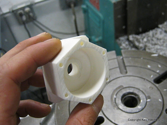
I had to make a proof of concept model out of cast plastic, I used the base of the mold as the base for the slug to be able to mill through it completely as it was a bit short for the part.
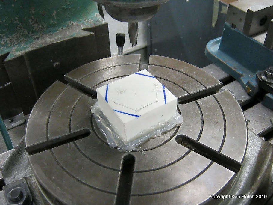
It was great practice but the design is not suited to this material. It can be milled much smoother but it has a tendency to crack if milled or lathed to thin.
I wont even show you the pictures of the rest, acrylic cylinders that chipped milling the exterior and melted ugly bores from not running the mill slow enough and with enough lubricant/coolant on the acrylic. A big fat mess that had me worried.
I thought, later proven correct, that the metal would be much easier to work with then the plastic. So I showed up at the midterm with some crappy parts and a sad look. My teacher was understanding and knew I had put in some time so he ok'ed my skipping the plastic version and going right to the metal final project.
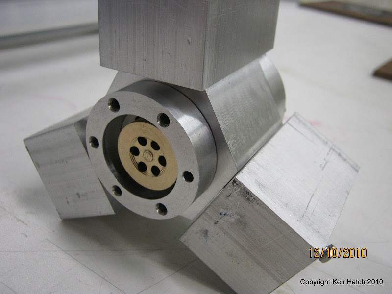
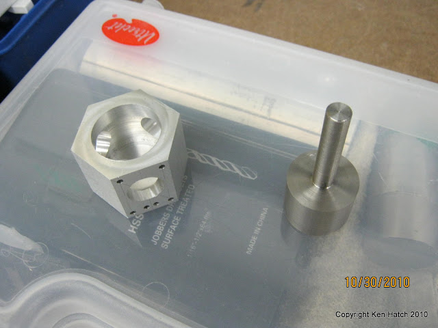
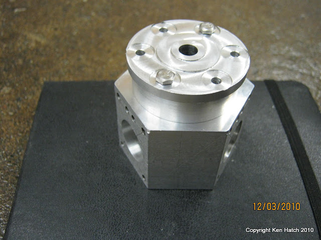
The crank case:
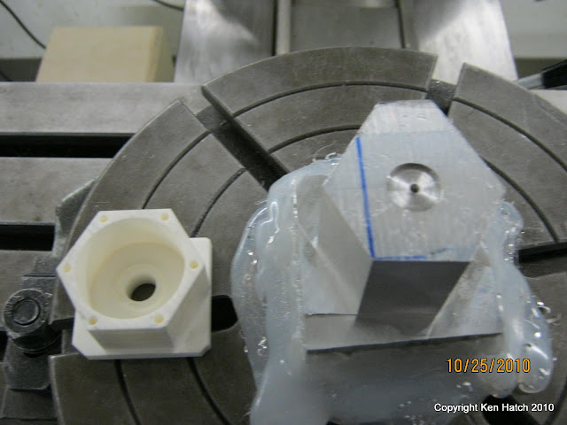
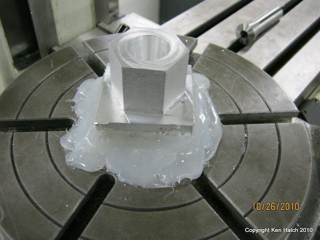
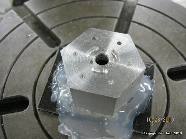
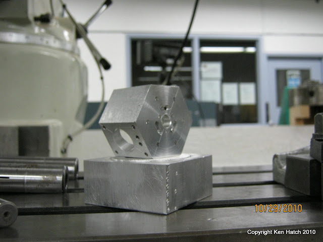
Metal is so much more fun then plastic!!! And yes that slug of aluminum is hot glued to the rotary table... ummm, yeah I don't do that anymore (and it was not my idea in the first place...). It did get hot, it did melt the glue, and it ALMOST flew off but for one little strand of glue that held it slapping against the mill end as I frantically reached for the switch. In that last picture of the crank case you can see the gouges in the square piece of aluminum its sitting on, that was the mill end banging away... So I I bought some bolts and nuts for the T-slots and luck saved me from flying shrapnel.
The crank shaft:
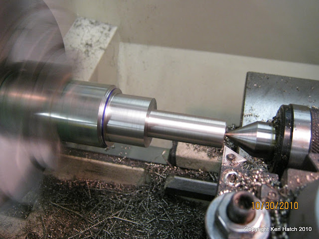
vid of the offset being made: http://picasaweb.google.com/kenhatch/Kens3CylinderRadial?authkey=Gv1sRgCInXw8aT_crtpgE#5551818142070777586
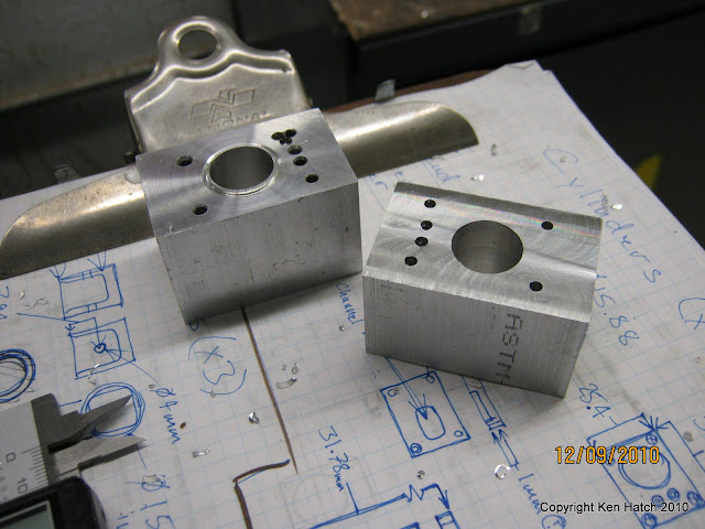
The cylinders were kind of tough due to my having blocks of aluminum rather then the round rods that Sbwhart used in his project. I had to deviate from his work log here but it was exciting to think up how to get them done with what I had.
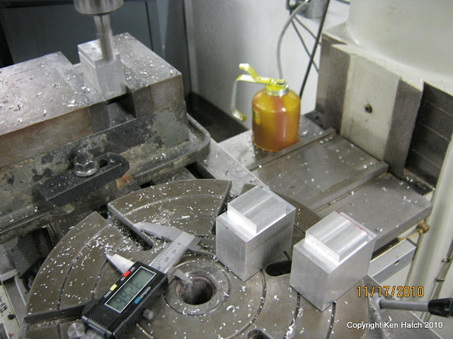
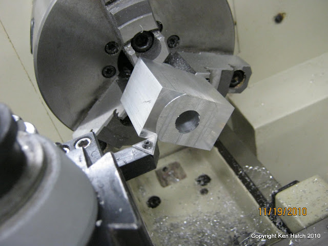
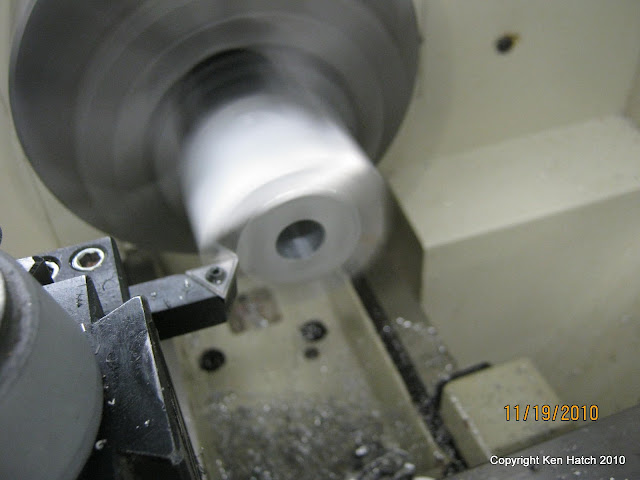
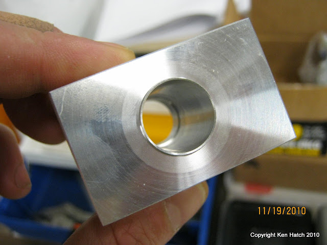
I should have done the bores on the lathe, but I didn't realize I could make a round extension for the 3 jaw chuck on the Lathe until after I had drilled them out. I will do it right on the next one, which will be a 6 cylinder based on this one.
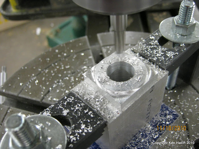
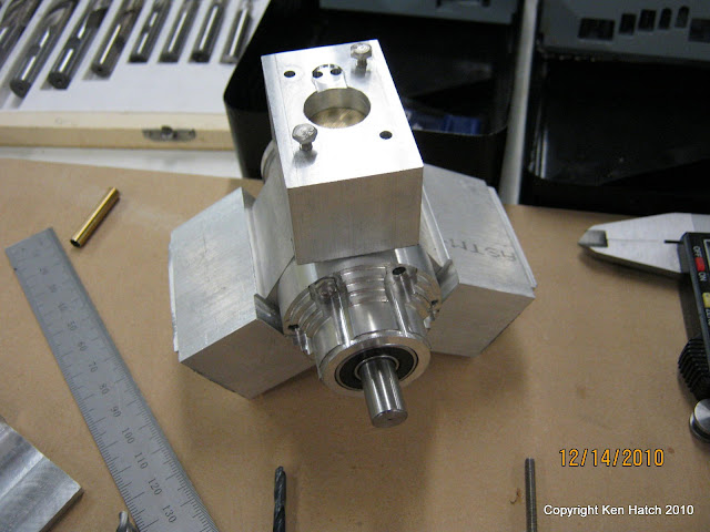
The steam chest:
Again with the hot glue. Ok I lied I guess I do do this sometimes. When its a short enough process that it wont heat the part to much, and when the part is so small the clamps will get in the way of the mill if they are directly on it.
So far so good, but this is around week 8 or 9 in the semester, I have other classes to take care of, and there are only 7 weeks left to get the engine built... I am still learning as I go but feeling much more confidant at this point. I am still thinking at this point that even if I don't finish I will learn more then if I had chosen something easier. I could not try to make an easier engine, giving up sucks worse then warm flat beer.
So at this point I have made some more parts and taken much less pictures. I started to get a very good idea of the time it takes to machine accurately and what I was coming up with as far as my time frame was cause for concern. I have no experience before this and had broken a few drill bits in parts I could not replicate in time, or money of which I had none more to spend on laundry much less scrape metal.
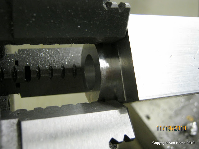
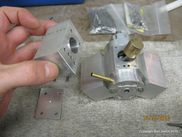
This is were the drill bits broke, the mill was slightly off and I was drilling through 30mm of crappy re-purposed beer cans.
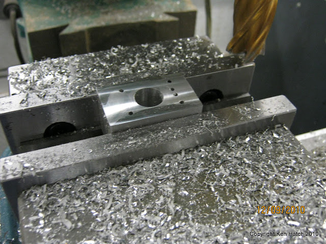
I got the bits out by drilling through from the opposite side with a cheap bit that was narrower then the holes that were supposed to be there. Then pushed them out using a steal rod that fit the new hole and the mill as a press. Whew, but what could happen next? I am a total newbie and haven't a clue but if it does happen I may not get this done in time!
At this point I start checking that the mill is level every time I begin using it. I share the metal shop with the rest of the students and some are pretty rough on the equipment. We have 4 mills but more then 2 in operating condition on any given day is a miracle.
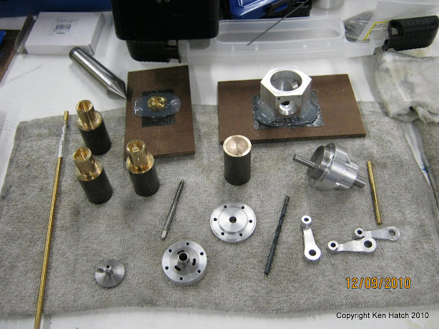
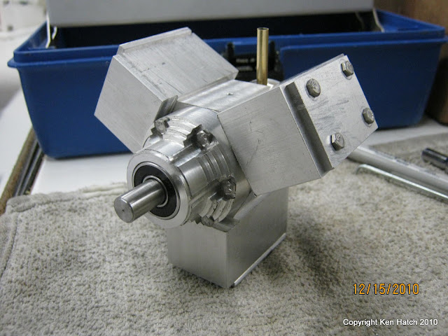
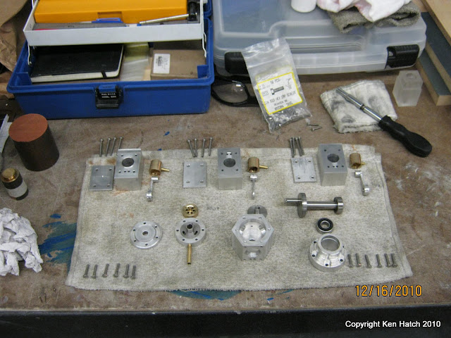
Getting close to being done, just about exactly on time to finish with maybe a day to spare.
Rough exterior is not finished, but it is functional and done enough for my teachers liking. He advised me my grade was pretty much secure and I should make sure I have my other classes taken care of. I did let some thing slide in other areas to get this done, but to me it wasn't work it was the thing I most wanted to do at any given time of the day.
Here is a video of it running, it is the worst video ever I am sorry to say. The blurry gauge, nothing to really show that its running besides the audio and the wobbles from the crankshaft not being balanced yet... I will get a better one next semester but for now the shop is closed and my studio does not have a compressor. I may try to use my espresso maker to run it, if it works I will post that.
http://picasaweb.google.com/kenhatch/LastDayOfTermUpload?authkey=Gv1sRgCKmW5PzA-dC7xgE#5551823464631459986
With out further yada yada, and to keep you interested, here are some of the pictures of my work so far.
I had to make a proof of concept model out of cast plastic, I used the base of the mold as the base for the slug to be able to mill through it completely as it was a bit short for the part.
It was great practice but the design is not suited to this material. It can be milled much smoother but it has a tendency to crack if milled or lathed to thin.
I wont even show you the pictures of the rest, acrylic cylinders that chipped milling the exterior and melted ugly bores from not running the mill slow enough and with enough lubricant/coolant on the acrylic. A big fat mess that had me worried.
I thought, later proven correct, that the metal would be much easier to work with then the plastic. So I showed up at the midterm with some crappy parts and a sad look. My teacher was understanding and knew I had put in some time so he ok'ed my skipping the plastic version and going right to the metal final project.
The crank case:
Metal is so much more fun then plastic!!! And yes that slug of aluminum is hot glued to the rotary table... ummm, yeah I don't do that anymore (and it was not my idea in the first place...). It did get hot, it did melt the glue, and it ALMOST flew off but for one little strand of glue that held it slapping against the mill end as I frantically reached for the switch. In that last picture of the crank case you can see the gouges in the square piece of aluminum its sitting on, that was the mill end banging away... So I I bought some bolts and nuts for the T-slots and luck saved me from flying shrapnel.
The crank shaft:
vid of the offset being made: http://picasaweb.google.com/kenhatch/Kens3CylinderRadial?authkey=Gv1sRgCInXw8aT_crtpgE#5551818142070777586
The cylinders were kind of tough due to my having blocks of aluminum rather then the round rods that Sbwhart used in his project. I had to deviate from his work log here but it was exciting to think up how to get them done with what I had.
I should have done the bores on the lathe, but I didn't realize I could make a round extension for the 3 jaw chuck on the Lathe until after I had drilled them out. I will do it right on the next one, which will be a 6 cylinder based on this one.
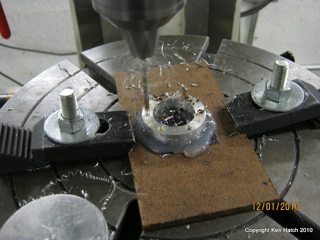
The steam chest:
Again with the hot glue. Ok I lied I guess I do do this sometimes. When its a short enough process that it wont heat the part to much, and when the part is so small the clamps will get in the way of the mill if they are directly on it.
So far so good, but this is around week 8 or 9 in the semester, I have other classes to take care of, and there are only 7 weeks left to get the engine built... I am still learning as I go but feeling much more confidant at this point. I am still thinking at this point that even if I don't finish I will learn more then if I had chosen something easier. I could not try to make an easier engine, giving up sucks worse then warm flat beer.
So at this point I have made some more parts and taken much less pictures. I started to get a very good idea of the time it takes to machine accurately and what I was coming up with as far as my time frame was cause for concern. I have no experience before this and had broken a few drill bits in parts I could not replicate in time, or money of which I had none more to spend on laundry much less scrape metal.
This is were the drill bits broke, the mill was slightly off and I was drilling through 30mm of crappy re-purposed beer cans.
I got the bits out by drilling through from the opposite side with a cheap bit that was narrower then the holes that were supposed to be there. Then pushed them out using a steal rod that fit the new hole and the mill as a press. Whew, but what could happen next? I am a total newbie and haven't a clue but if it does happen I may not get this done in time!
At this point I start checking that the mill is level every time I begin using it. I share the metal shop with the rest of the students and some are pretty rough on the equipment. We have 4 mills but more then 2 in operating condition on any given day is a miracle.
Getting close to being done, just about exactly on time to finish with maybe a day to spare.
Rough exterior is not finished, but it is functional and done enough for my teachers liking. He advised me my grade was pretty much secure and I should make sure I have my other classes taken care of. I did let some thing slide in other areas to get this done, but to me it wasn't work it was the thing I most wanted to do at any given time of the day.
Here is a video of it running, it is the worst video ever I am sorry to say. The blurry gauge, nothing to really show that its running besides the audio and the wobbles from the crankshaft not being balanced yet... I will get a better one next semester but for now the shop is closed and my studio does not have a compressor. I may try to use my espresso maker to run it, if it works I will post that.
http://picasaweb.google.com/kenhatch/LastDayOfTermUpload?authkey=Gv1sRgCKmW5PzA-dC7xgE#5551823464631459986
")