My "Chuck's Horizontal Single"

Home Model Engine Machinist Forum

Help Support Home Model Engine Machinist Forum:

This site may earn a commission from merchant affiliate links, including eBay, Amazon, and others.
Brian,

Chuck Has been Very helpful regarding this build, Bog has built a very similar engine and also is willing to answer questions, and I would also be happy to answer any questions you had. It has not been terribly difficult so far, but it does involve some millwork and turning between centers with a lathe dog for the crank (I am working myself up to that one :eek: )

Regards, Bret
 
I bought a faceplate and lathe dogs when I got my lathe, and have used them once just to see how they worked. I turned a peice between centers and used the lathe dog, and it is very simple. I have a small mill on order,--it should be here by the end of June. ---Brian
 
Bret and Brian,

For this sort of engine a built up crank is perfectly OK, and dead easy to do if you don't fancy turning one out of the solid.

If you go to the bottom of the first page and the first bit of the second, it shows two different methods, you can just as easily use steel, and you can pin and loctite or silver solder, the free end on the crankpin can be pinned or soldered instead of the grubscrew.

http://www.homemodelenginemachinist.com/index.php?topic=862.0

John
 
John,

I will probably try both turning between centers and doung a built up crank A-LA-Bog and see which one turns out best, I like the built up idea in that I can put a ball bearing on the crank journal too. But I need to learn how to turn between centers sometime ::) and as they say, there is no time like the present.

Today's installment is kinda short as we spent most of the day working with the alpacas. (we raise them) I did get most of the rest of the shaping done on the frame side parts, no real tips here, just lots of chips on the floor.

-Bret
pic001.jpg
 
Bret,

I think what you are doing is the correct way.

You might HAVE to make a solid crank in anger one day, and doing a relatively easy one now will at least give you a good insight into method, and what needs to be done.

I was just trying to give you options.

These are not my ideas by the way, they come from the distant past.
I just showed how easy they are to do.

Build is looking real good by the way.

John
 
John,

Belive Me when I Say: :bow: I Appreciate ALL the Input I Can Get! :bow: I don't get a chance to spend time arount machinists in my line of work, so I really appreciate all the tips everyone is willing to offer, it's kind of like a virtual apprenticeship ;D Soo thanks again and keep em coming everyone :bow: :bow:

-Bret

Cool, I didn't know you could get the little guys to glow red too!! :big:
 
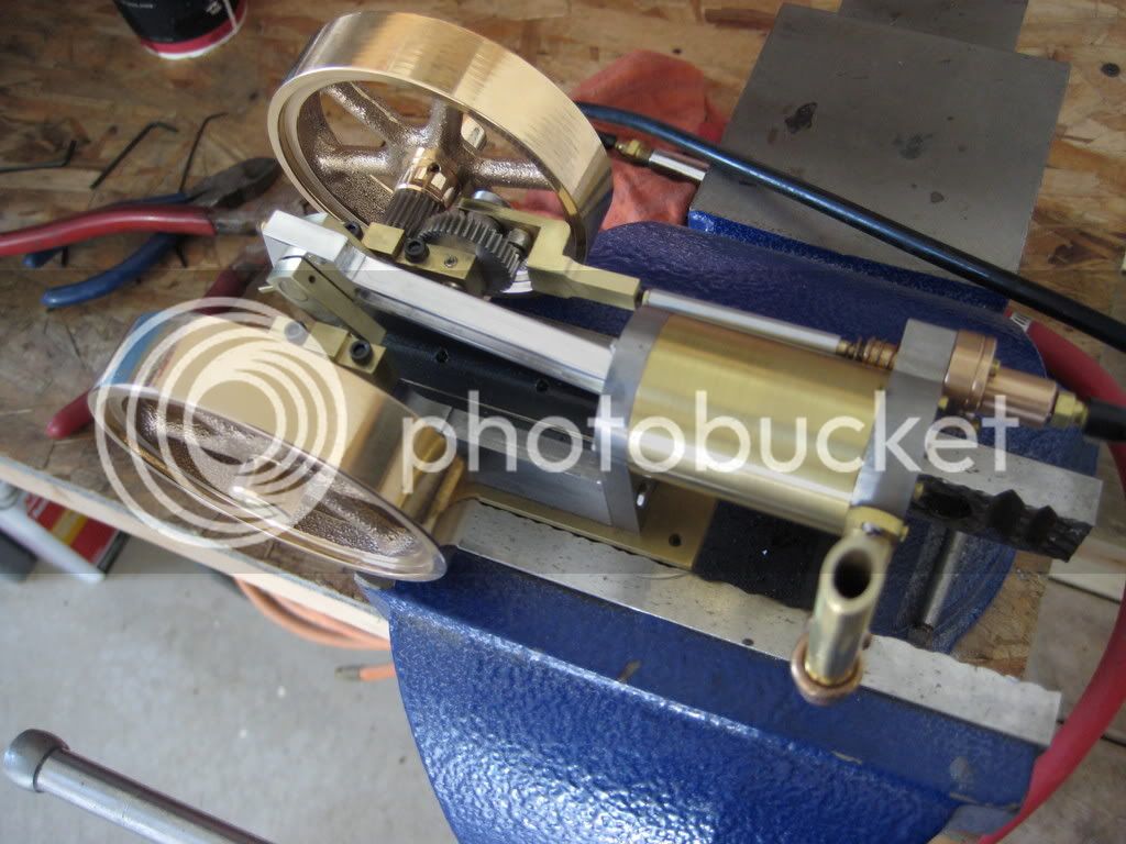
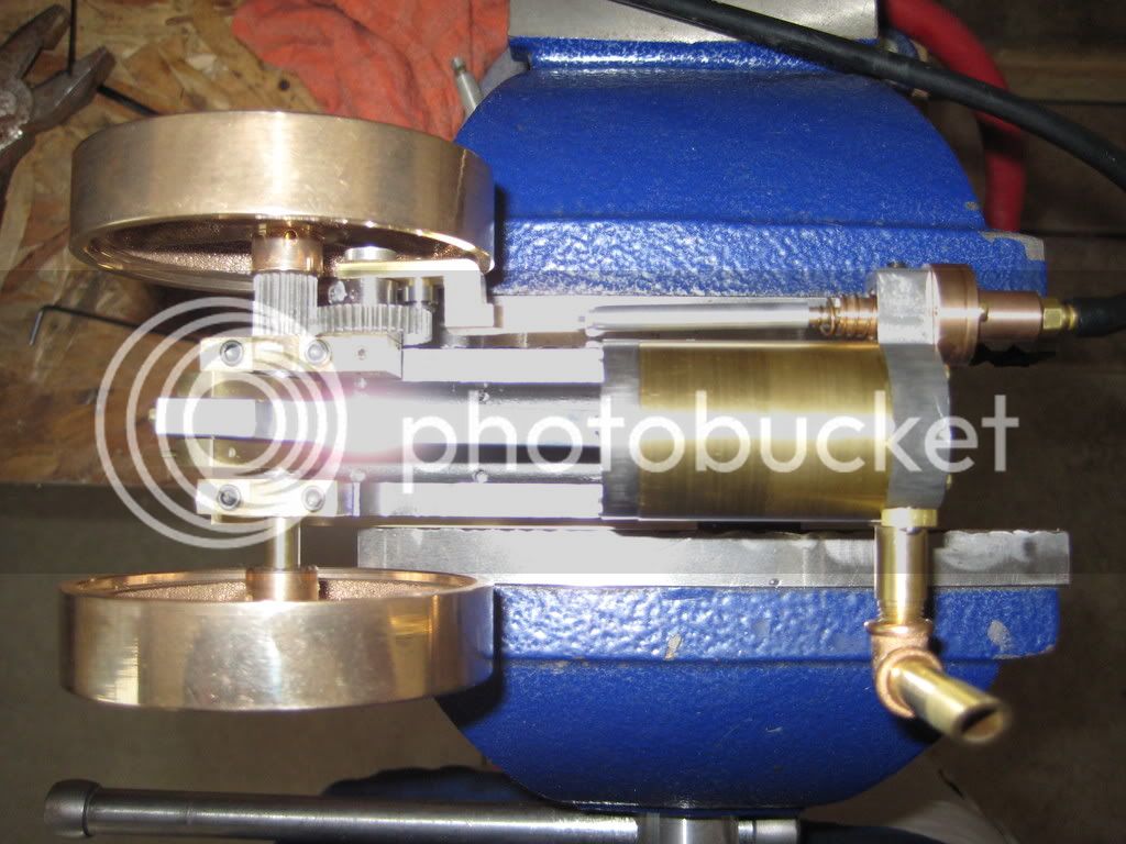
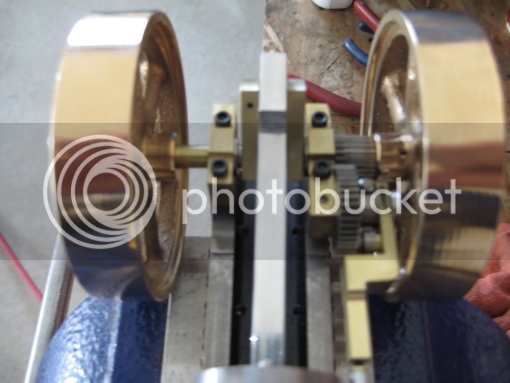
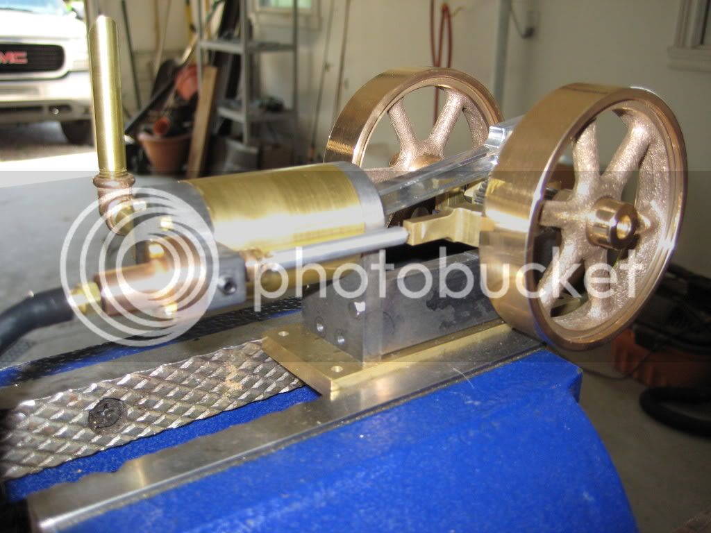
Progress and Pictures ;D

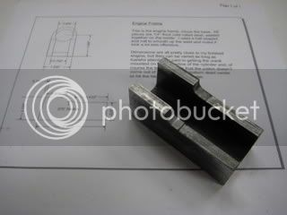
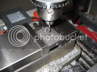
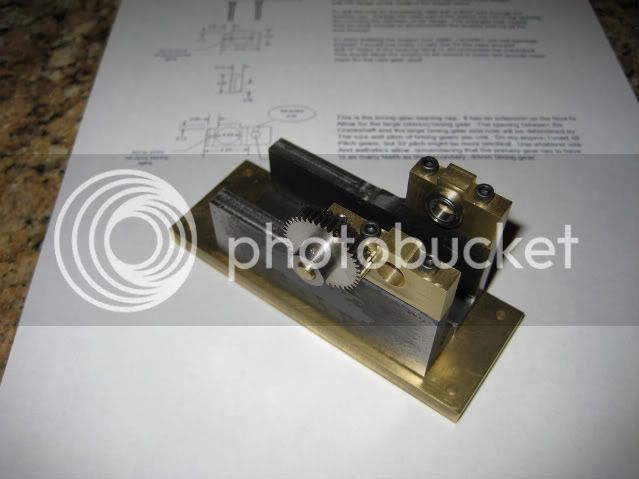
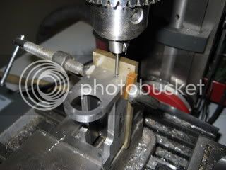
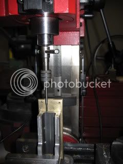
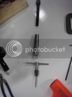
First the Base: I took Chucks advice and mounted the angle to a brass intermediate base (which will eventually be mounted to a sculpted ali base for a little bling A-La-Bog ;D) with 2 ea 6-32 screws per side at stations 1.00 and 2.oo from the crank end. Then I set about the cylinder mounting end and chucked a pc of 1/4 by 1.25 cold rolled in the 4 jaw and drilled and bored the .900 hole for the cylinder. Then, taking to the mill, I drilled 4 clearence holes for 4-40 scrws at.125 from the edge 2 @ .600 high on the sides, and 2 equidistant in from the ends. I then clamped the whole shebang in the vise and using the reverse end of the drill bit as a centering guide, then flipping it over to spot drill the holes as a guided center drill, I drilled and tapped the frame for the endpiece. As the unit was too highfor my spring loaded center, I took my 1/8" collet, a 1/8" pin, and as shown in the photos set up a nifty little tap centering and following device, I found that the weight of the collet and loose drawbar are just enough downforce to get the tap started nicely.
pic009.jpg

pic010.jpg

pic011.jpg


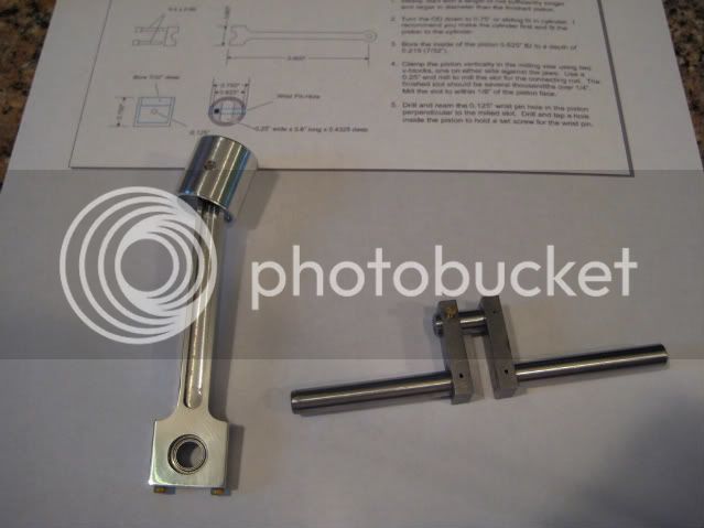
Then I started work on the valve head. I did mine slightly different than Chuck. After squaring up the stock and drilling and reaming the 3/8" hole for the valve body, I set it up vertical in my mill and drilled a .120 hole thru, clearing chips frequently. then enlarging to a letter F drill I drilled to the specified depth. I then reamed the hole with a 1/4" reamer.
Then placing it on it's side I drilled the 1/8" inlet and exhaust holes.
pic007-1.jpg

I then shaped the outside with the mill and belt sander.

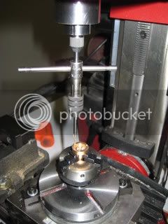
I got a chance to Use my rotary indexing table for the bolt holes and boy was that awesome ;D it really takes the guesswork out of things and alignment was spot on.
pic006-1.jpg


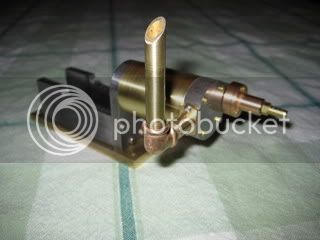
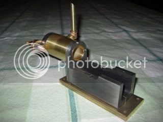
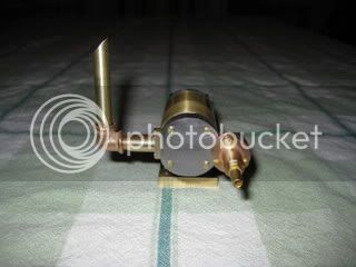
So Here are some pics of the progress so far. I added a Beveled exhaust pipe for a more hit and miss feel
pic012.jpg

pic013.jpg

pic014.jpg


-Bret
 
That's looking mighty fine there Bret ;D

I like the contrast of materials and the exhaust....This is another engine on my list so I'll be watching for the rest of your build quite carefully :)


Ralph.
 
Dang, Bret, you're kind of one-uppin' me here. I may have to build another one that looks as good as yours!

Mighty fine work...

Chuck
 
Am I getting a bit senile or what??? I keep looking for Chuck to post more drawings, and the last update I can find on his thread is the 09-June. Am I looking in the wrong place or is chuck just taking his time with more posts?
 
Chuck,

Thanks for the compliment ;D But I think that John Deere engine of yours will be more than enough competition 8)

Brian,

Chuck's drawings are like fine wine, they are aged to perfection and you don't want to rush them or all you get is sour grapes :big: (just kidding) I think he is working on the next installment, and I am finishing up the flywheels tonight. Will try and post on them soon. I ordered a half dozen extra, cause sooner or later someone at Tiny Power is going to realize they are priced well undermarket value.

-Bret
 
Brian Rupnow said:
Am I getting a bit senile or what??? I keep looking for Chuck to post more drawings, and the last update I can find on his thread is the 09-June. Am I looking in the wrong place or is chuck just taking his time with more posts?

I've been out of town for the last week, just got back home last night.

I'll pick up again tonight. Don't have a lot of drawings left to do.

Chuck
 
Progress ;D I finally got my Honeydo list down to a manageable level and was able to sneak down to the workshop for a few minutes of bliss. :big: I finished up the bearing blocks differing slightly from chuck's design by using 1/4 id by 3/8 od flanged bearings as described previously. This leaves plenty of room for the 4-40 holdown bolts. My locatons are as follows: with 0 being the aft end of the engine and centerline stations being given, 250 aft bolt, 550 crankshaft, 850 front bolt, 1172 intermediate shaft.

The photo shows the bearing not yet press fit into the hole left by the 3/8 endmill bored 100 thou deep for it. my thru drill was a 5/16 endmill

pic.jpg
 
I bit the bullet and completed a crankshaft today :D I used Bog's built up method with roll pins and loctite to allow the use of a ball bearing on the connecting rod big end. It turned out pretty well. Made from drill rod and cold roll. I have the parts ready to try a silver soldered brass crank tomorrow, so we will see which I like better.

-Bret
 
You're really doing a crackerjack job on this engine, Bret. It's looking great!

Chuck
 
Well a bit of a setback today :-\ :'( On the plus side I finished the piston and Connecting Rod. I put a 1/4 by 3/8 by 1/8 ball bearing in the big end and added flutes and dummy 2-56 brass bolts for a little Blingage ;D The setback came when I went to fit everything up and tried to slide the bearings on the journals. HOW COME I NEVER KNEW THAT 1/4" GROUND AND POLISHED DRILL ROD IS ACTUALLY .252 DIAMETER???? SILLY ME THOUGHT WHEN I ORDERED 1/4" I WOULD GET 1/4" :mad: :mad: :mad: BUT NOOOOOOO! Ok, done venting, I guess I will be finishing the silver soldered brass crank with the honest to goodness 1/4" (.2500000000000) Ok .250 stock. Here is a pic of the Piston, Con Rod, and ill fated Crank , which has scince found a home in my recycle bin and I'm sure a use on a future project. (maybe a finger engine?????)

-Bret

pic025.jpg
 
So, Your crankshaft is oversized by.002"? Can't you just polish it down with some emery?

Wes
 
Bret,
Drill rod is normally oversize a small amount to allow grinding to size after hardening. I have found that on small sizes it can vary quite a bit. I have bought packages of 5 from Online Metals and then measured and sorted them so I can use them in different applications.

For shafts where they have to fit a bearing, I use 1144 stressproff TGP. TGP stands for Turned, Ground, and Polished. It is held to close tolerances to use in Swiss type CNC lathes where the material is fed through a close bushing by a sliding headstock. The typical tolerance on it in small sizes is +0.000/-0.001. A lot of suppliers have it. Speedy metals has 1/4 inch diameter for about $0.90 per foot. It also machines very well as it is made for screw machines.

Gail in NM,USA
 
Bret, lovely job on the crank and piston setup.

I said you would most probably have no trouble with making a built up crank. Didn't think about the material size issue though.

But think positive thru failure, and of the two lessons you have learned from the exercise, you now know how easy it is to make a built up crank, and you should always check your bearings for fit before anything else. I can almost guarantee you won't make the same mistake again.

John
 
Here are the updates to complete the engine. First is a photo of the silver soldered brass crank. It was way easier than I was expecting. I used Bog's trick of solder rings pushed up next to the web then heated it all.

pic042.jpg


Valve train was built pretty close to Chuck's specs other than using 1/8 ID by 1/4 OD roller bearing. Cam was a 4-40 button head screw with a nut under loctited in the setscrew hole then rough filed to shape

pic047.jpg


pic046.jpg


The valve rod is drilled to accept a cap 2-56 screw to use as an adjustment

pic045.jpg


Here are some assembled photos, pre polish of course :big:

pic048.jpg


pic049.jpg


pic050.jpg


pic051.jpg
 

Latest posts

Back
Top