My build of Brian's double scale beam engine

Home Model Engine Machinist Forum

Help Support Home Model Engine Machinist Forum:

This site may earn a commission from merchant affiliate links, including eBay, Amazon, and others.
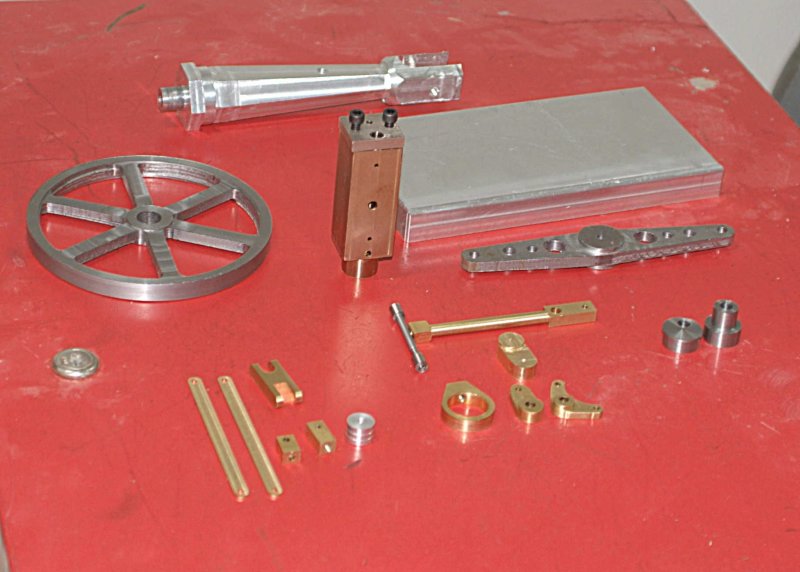
First night back in the school shop. I finished the 2nd piece of the eccentric, with the offset hole and an outer rim similar to what Gail did. I'm undecided about how to attach the two pieces, although a small capscrew seems the most logical. The inner piece is not as tight a fit to the flywheel as I would like, so it looks as if I will need to use locktite there.

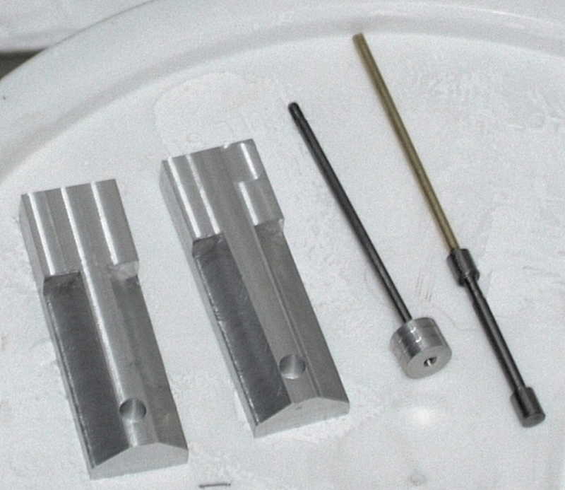
Then I started on the valve, and made a piece of scrap after 2 hours by turning it undersize. Started a second piece and after some "rough" turning realized that the two valve rounds are further apart than the drawing by .015". Maybe Brian or someone can tell me if this is a critical dimension. If not I can continue on tomorrow, or else start on V3.

Lucky for me the school has about 100' of 1/2" brass rod available, or this could be an expensive lesson. 8)

I'm also coming to the conclusion that trying to make precision parts on the lathe when you're tired and your feet hurt is counterproductive. I'm thinking that when I fubar a part, I should start making a different part before trying to correct the mistake the next time.
 
Kvom--I don't know how critical that will be. At this point I would take a "try it and see" attitude. Its easy enough to replace later if you gave to.---Brian
 
I made the piston tonight. Since I had the cylinder already, I was able to trial fit while still on the lathe. Fit seems good prior to any lapping or run-in. I may have printed an old version of the plan as it shows the center hole thread as 2-64. Since the piston rod is 1/8", I went with 6-32 as I have that tap/die combination.

My attempt to salvage the valve was a failure, as it broke when I was turning down the inner shaft. I think for V3 I will fabricate it from 1/8" drill rod and three separate brass pieces threaded on.

I also cut a piece of brass for the crankshaft, and I am going to try this as the the first piece I make in the home shop.
 
I finally had the chance for a "work" session on the new shop, and decided to attempt the valve once again.

I had 3' of 1/4" drill rod from Enco, so my plan is to make the two valves from this and connect them and the top piece with 1/8" brass rod. So after 2 hours or so of trial and error I finally had the first valve. ???

Things started off smoothly. I cut of about 3" of drill rod with a hacksaw and chucked on the lathe with the rubberflex collet system. I made a clean facing cut, center drilled the end, and then drilled about 1.5" into the rod with a #38 drill. Then tapped the hole 5-40.

My next move was to try parting off about .4", but when the parting tool was just a few thousand into the rod the rod snapped off at the chuck. Seems even very slow cross feed put too much strain on the rod. :'( Now I am wondering if I could have parted this with the end supported by the live center. That's an experiment for this afternoon.

My next though was to try to chuck a .5" length of rod, drill & tap, then face to length. My 6-jaw chuck wouldn't close far enough, and the collet chuck couldn't grip a piece that small.

Next try: put a .5" piece in a 5c collet mounted in a hex collet block, and clamp the collet block in the 6-jaw. This probably would have worked OK, but I didn't have the "pin spanner" needed to tighten the collet enough.

Final try was to chuck a 2" piece in the jacobs collet, drill & tap as before, then cut off .5" with the hacksaw. Now I could mount the .5" piece in the 5c collet and use the cam closer on the collet block. I put the collet block on the mill vise and used an end mill to reduce to size.

So 2 hours later I had made one tiny part. But I did learn things about the new-to-me lathe.

On the shopping list:

small drill chuck with MT2 shank
pin spanner for closing collet blocks
 
Continuing on the learning curve, I made the second valve and connected the two with a piece of 1/8" drill rod threaded on both ends. Although I drilled and tapped on the lathe, the two pieces are not precisely straight, so I figured they would not work smoothly in the valve bore.

Back to the lathe to turn both valves and the connecting rod from a single length of 1/4" rod. Took a couple of tries for various reasons, but the last version looks as if it might work. At least I'm getting faster on the re-dos.

Added a new hacksaw blade to the shopping list.
 
Pictures! We need pictures!

Betcha the bandsaw repairs just moved up a few spots on the to-do list...


Kevin
 
Waiting for my camera to be repaired.

Since the shop is still a work in progress I can't really move a lot more stuff inside until the inspections pass. So I am working out of a rolling tool cart. I don't want to take the bandsaw apart until after the inspection. Anyway, cutting 1/4" drill rod is probably just as easy with the hacksaw.
 
I just read ozzie46's thread on building this engine at Elmer's scale. He's a better man than I. He did post a copy of Elmer's plans, which I had not looked at previously. Reading it answered some questions I had about how the valves worked and how one would set the corresponding positions of the valves, eccentric, and piston to make it run.

I also discovered that the cross-drilled valve inlets need to be plugged at the outside of the cylinder, a fact that is logical in hindsight but was not to a newbie such as myself.

So I would recommend that anyone contemplating this version also get Elmer's plans.
 
Went to class tonight and machined the crankshaft part on the rotab. I think I will try a press fit on the rods and/or loctite before trying any silver solder. I also got to regrind my HSS lathe bits with a lot more side relief, which will hopefully allow me to finishing turning the valve, version #5. As originally ground , I couldn't get the tool in close to the Jacobs collet without hitting the chuck.

I'm about ready to start fitting the various pieces together. The only big piece left are the support legs for the flywheel, once I come up with a design I like. I still need to drill mounting holes in the base.
 
Hummmmm

Is that camera fixed yet?

....... How about now? ;)

Looking forward to pictures!

Rick
 
The camera shop quoted $400 to repair the Fuji S3, clearly too much to pay to fix a camera that sells used on eBay for around the same amount. Since the problem was with the battery power circuit, I tried it with the AC power adapter, and it does work in that mode. So for taking pics of models it is fine.

Anyway, here are the parts I've made to date. Not much to look at for 6 months effort. Still, 4 types of brass, 4 types of steel, and some aluminum.

large.jpg
 
It's not like you've had a few other things on the go at the same time. Progress is progress. Your engine is coming along just fine and looking good.
Regards
Ernie J
 
Very nice work. :bow:

Best Regards
Bob
 
kvom, thanks for the great walk though. I have just read it start to finish, I wouldn't be concerned on the amount of time spent. It's what you get out of it that counts.
 
kvom,
I didn't realize just how much you've done until you laid it all out like that. That's quite a bit considering you were also building a shop and could only work on it during school hours.

However, now you get to finish it up in your own shop ;D
 
kvom,

Excellent work. You have inspired me to build Brians Beam Engine. Also, thanks for your excellent detail you provide on your post. I am new to machining and you process notes are very helpful! I just bought an 8" rotab so I guess I will start with the flywheel this weekend.
 
I made the flywheel support tonight. Rather than 1 piece I made each support from a separate piece of aluminun that I will bolt to the base from below.

I also made the guide rod support with a little more bling than just a straight rod. I am going to use the top as the guinea pig for cutting threads on my 10ee.

Also finished drill/ream of through holes on the crankshaft. I need to see how a press fit of the drill rod pieces will go. I bought a small arbor press from Enco, so we'll see if it is up to the job.
 
Some minor progress this afternoon after a couple of hours in the shop.

original.jpg


On the left are the flywheel support arms I made on thursday.

Today I made the piston rod. It's not very exciting, but it gave me the change to try out the threading capability on the 10ee. I had previously tapped the piston for 6-32, not having a 5-40 tap. However, 5-40 is really the best thread for 1/8" rod. So first I threaded the piston end 6-40, first cutting partial threads on the lathe, and then finishing with the die. Doing it this way helps ensure that the die cuts straight along the rod. I then repeated the process on the other end for 5-40. Next time in the shop I'll attempt to make the piston rod end. I also used some fine emery cloth to "lap" the piston rod on the lathe, using the cylinder head as a check for fit. After a fair amount of polishing I have gotten a nice sliding fit through the head.

Having managed somehow to make a partial valve body and failing several times to turn a complete one, I drilled and tapped the end 5-40, threaded the end of a peice of 1/8" brass rod to fit. I'll cut the rod to length and thread it, then make the end of valve at the same time as the piston end.

I also learned that it is better to ream the cylinder and valve bores AFTER cross drilling, as the drilling results in burrs in the bores. I will need to re-ream them to clear the burrs before trying to fit the valve and piston.
 
Back
Top