My build of Brian's double scale beam engine

Home Model Engine Machinist Forum

Help Support Home Model Engine Machinist Forum:

This site may earn a commission from merchant affiliate links, including eBay, Amazon, and others.
Waiting for more pictures. I am thinking of trying to build this one.

Eric
 
Better luck last night with the valve linkage arms. I cut a strip of brass 4" long and about .5" wide from a piece of .25" thick brass on the bandsaw. After milling the two sides parallel and to final length, I used the corner rounding bit to form the profiles on each end. Note the soft jaws in the vise.

large.jpg


Next I center drilled, then drilled the through holes. Then carefully sliced the piece down the middle on the bandsaw:

large.jpg


Now reclamp each and mill down to final .063" thickness:

large.jpg


Flush with success, I decided to move on to the piston rod guide. Cut a similar size brass piece (4" x .5" x.25) and milled it down to 4 x .375 x .25. Then I center drilled each end with a tiny size 0 drill. On to the lathe where I made this setup:

large.jpg


With very small cuts @ 500 rpm I turned the center down to .25" diameter, leaving oblong sections on each end to facilitate clamping. Then back to the mill to drill the holes:

large.jpg


I'll finish the end profile on the rotab, but leave the bit on the other end until final assembly in case some further milling is necessary.

It's nice to know that I can make .25" brass rod from bar stock if needed.
 
Spent the past two evening classes making the column. I might have gone overboard on "bling" but I wanted to try some different techniques. 6061 Al:

large.jpg
 
Kvom,

That is one very good looking column.
champion.gif


Regards
Bob :)
 
kvom, if you have learned enough to do a column that looks like that, I say you are getting your money's worth and then some out of your class!! That thing is smokin'!!! :bow:
 
Kvom .............. 8) .............. nice work feller :bow:

CC
 
Well that there is one nice piece of work :bow: 8)

I like your style Kvom ;D


Ralph.
 
Nice Idea!!! It seams to upgrade the project.... :bow:
Paolo
 
This time I worked on the large/small ends of the eccentric rod:

large.jpg


The large end was mainly made on the rotab. This time I had a 4"x4" piece of .25" brass, and rather than cut out a blank for the piece, I used the entire piece so as to have lots of room for clamping. I used a small center drill to mark the center point of the hole and used this as a reference to center it on the rotab. The brass was then clamped to a sacrificial piece of Al.

I had calculated that the angle formed by the sides and the axis is 25.25 degrees, so having positioned a .25" endmill to cut the radius, I turned the outside curve over an angle of 230.5 degrees. once the curved portion was cut through into the Al, I drilled and reamed the .75" hole. Then having turned the rotab to the ends of the curve, I could use the table axis to cut the straight portions. These I did not cut all the way through, leaving about 1/16". I then cut through this kerf on the bandsaw and then finished milling the straight portion and threading the rod hole clamped in the vise.

The smaller end is pretty straightforward, although milling the blank to the proper dimensions is tedious. I don't have a rounding table, so I will probably just file the end radius once I have the threaded connecting rod to use as a handle.
 
Very nice work Kvom. When I built my first one for the beam engine, I bored the hole and chopped out everything else with the bandsaw, then filed it to shape.---Brian
 
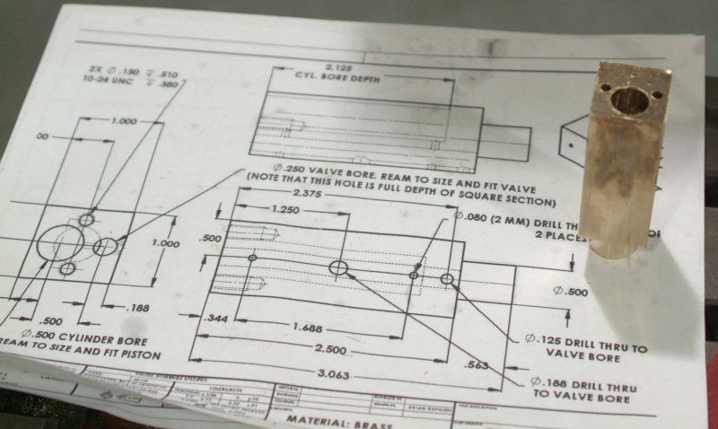
Last week I made a nice piece of scrap, trying to mill the cylinder cap on a too small piece of metal. So yesterday I decided to start on the cylinder, thinking that once it's done I can use it to ensure that the cap fits properly.

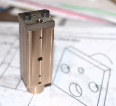
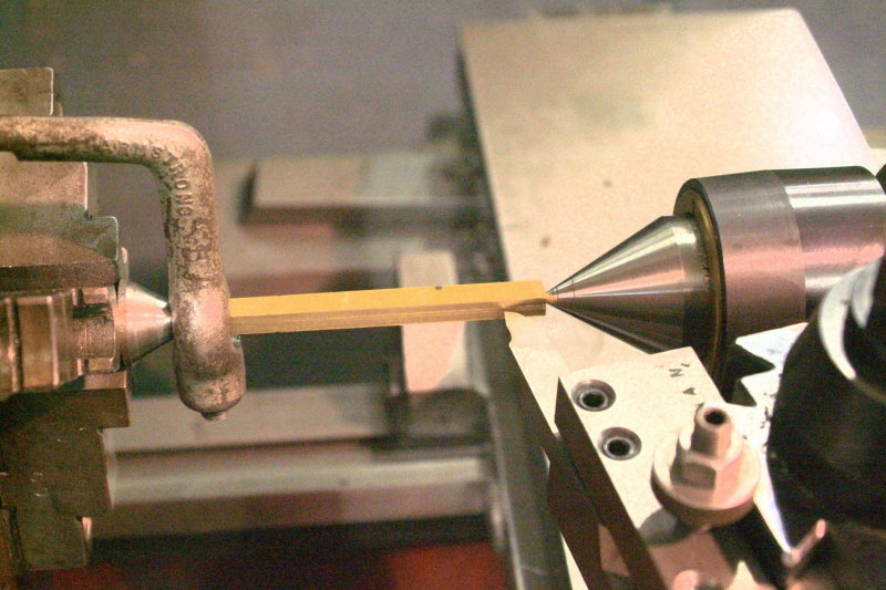
The instructor furnished me with a bar of brass of "unknown ancestry", saying that it had been in the school storeroom for many years. The bar has a cross section of 1x2" and was about 8" long, quite heavy, and with a dark brown surface patina. I cut off a piece with the bandsaw, and it is considerably harder than 360 brass. In any case, once milled it has a nice yellow-orange color very close to 10K gold. One person in the shop opined that it might be beryillium-copper.

I machined a piece down to 1x1x3.5". The metal seems to like low speed (500 rpm) and small cuts with a 4-flute 1/2" mill. Any more and it gets hot and throws off dark orange swarf.

I then center-drilled each end and took it to the lathe to turn between centers in order to form the round end. I decided to leave this end at 3/4" diameter. Here again I turned it at 520 rpm and took small cuts.

Back to the mill to drill the cylinder bore. I set the mill's quill stop for a 2.25" depth, as the piece is longer than the plan's dimension, and I plan to mill some off the top at the end. Started with a 1/4" drill, then 31/64, and finally a 1/2" reamer. Even with lots of cutting oil it needed a lot of pressure to ream the hole. Finally I tried to square the bottom of the bore with a 1/2" 2-flute mill, but even with a lot of pressure on the spindle handle it's still not flat. I wonder if that matters (anyone?).

Next week I should be able to drill the valve bore and the other holes, and make a start on the cap.

large.jpg
 

Looking great!

especially the column. Progressing very well. Engine and skills!
 
I finished the cylinder last night. Tried a recommended technique for drilling the valve bore. If I chucked the drill for the full depth there would not have been much of the drill shaft in the chuck jaws with corresponpondimng lack of rigidity. So I chucked normally and drilled about half depth. Then I lowered the knee .7" to clear, chucked the drill on the end, positioned it over the hole, and raised the knee. Now the drill was guided by the hole and I could finish to depth. A bit extra work, but the hole is likely to be straighter than it might be otherwise. Finshed off with a .25" reamer, then drilled the cross holes.

I started on the cylinder cap but didn't have time to finish. I turned the part that mates to the cylinder bore on the rotab (tedious) and could have done it much faster on the lathe, in retrospect.

We have only two more sessions of class before the break, so I won't finish the engine at school. Hopefully I will have my mill working at home next week and can make some progress here.
 
Third try at making the cylinder head succeeded.

I took a slice of the "silver brass" 2" rod that Cedge gave me, mounted it on the rotab, and turned down the round portion. In retrospect this could have been done faster on the lathe, but the finish was definitely better than what I attained when trying to turn it earlier.

Then over to the mill to machine two parallel surfaces for clamping and to establish a reference for drilling the holes:

medium.jpg


I then machined the sides square. On each side I first used a 3/8' roughing mill that I was given recently; definitely a plus in removing material quicker. I did discover that clamping the sides resulted in distorting the holes slightly, so to do it again it would be preferable to drill after the milling is done. In any case, I redrilled and re-reamed the pushrod hole.

Mounted on the cylinder:

medium.jpg


My first "assembly". Needs a bit of filing yet, as well as lapping the hole for the pushrod.

I like the color contrast between the various types of brass I'm using.
 
Looking good kvom ............. and from the sound of things you should be up and running at home shortly so, as you say, things will progress quicker ............... great thread, keep it coming 8)

CC
 
A couple of more fiddly bits tonight. Made the piston rod end and then the inner half of the eccentric. I'm making the eccentric in two pieces like Gail showed. The first try I found a piece of stainless steel and messed it up trying to drill the setscrew hole. Went back to CRS with better results.

Compared to Brian I feel glacial.
 
I made up an Excel spreadsheet listing all the parts in the plans and marking those I still need to make. Looks as if I'm about 75-80% of the way done, given that three of the parts are just the rods.

Looking for advice on assembly.

I'm thinking that in cases where the plan shows "sliding fit" but is supposed to be secure (e.g., the two rods forming the crankshaft), I should be able to make these a press fit. If I ream a .25" hole then a .25" piece of drill rod pressed into the hole should be a pretty tight fit and not really need to be soldered. Am I all wet here?

For rods that need to rotate within holes, is it "OK" to ream the hole with the next size reamer, which would generally give around .003" clearance? Or is that too loose?

Assuming I'm not in left field with these ideas then I ought to be able to avoid solder and loctite almost everywhere.
 
Three thou is a bit loose, but it will work. I'd try to get it closer, though.
 
kvom said:
I made up an Excel spreadsheet listing all the parts in the plans and marking those I still need to make. Looks as if I'm about 75-80% of the way done, given that three of the parts are just the rods.

Looking for advice on assembly.

I'm thinking that in cases where the plan shows "sliding fit" but is supposed to be secure (e.g., the two rods forming the crankshaft), I should be able to make these a press fit. If I ream a .25" hole then a .25" piece of drill rod pressed into the hole should be a pretty tight fit and not really need to be soldered. Am I all wet here?

For rods that need to rotate within holes, is it "OK" to ream the hole with the next size reamer, which would generally give around .003" clearance? Or is that too loose?

Assuming I'm not in left field with these ideas then I ought to be able to avoid solder and loctite almost everywhere.

Kvom--I soldered the crankshaft on mine.--That being said, probably a hard press fit will do.---I'm more comfortable with soldering than I am machining to "press fit" tolerances. ;D ;D I have a set of "on size" reamers. I find that stock peices of round cold rolled steel are always just a half thou. or so undersized, so that works fine for bearing surfaces. I think I read somewhere that drill rod was slightly oversized, but I'm not certain.---Brian
 

Latest posts

Back
Top