My build of Brian's double scale beam engine

Home Model Engine Machinist Forum

Help Support Home Model Engine Machinist Forum:

This site may earn a commission from merchant affiliate links, including eBay, Amazon, and others.

kvom

Well-Known Member
HMEM Supporting Member
Joined
Jun 4, 2008
Messages
3,285
Reaction score
630
I am going to build this during the fall quarter in the school shop. My intention is to deviate from the plans in "bling" aspects while following the critical dimensions. My intended mods include:
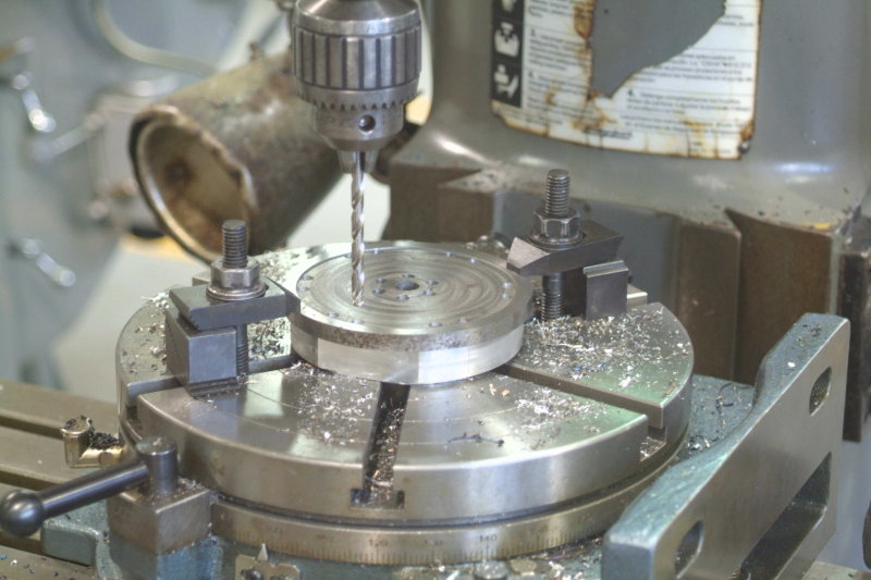
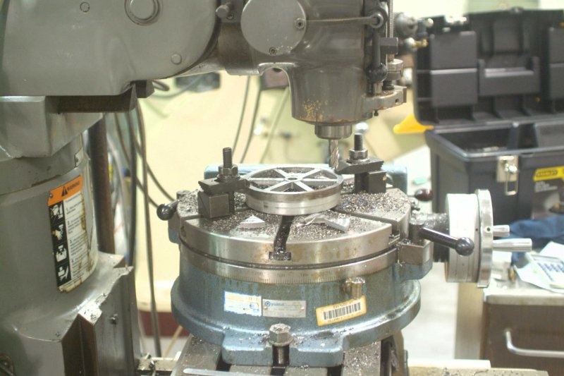
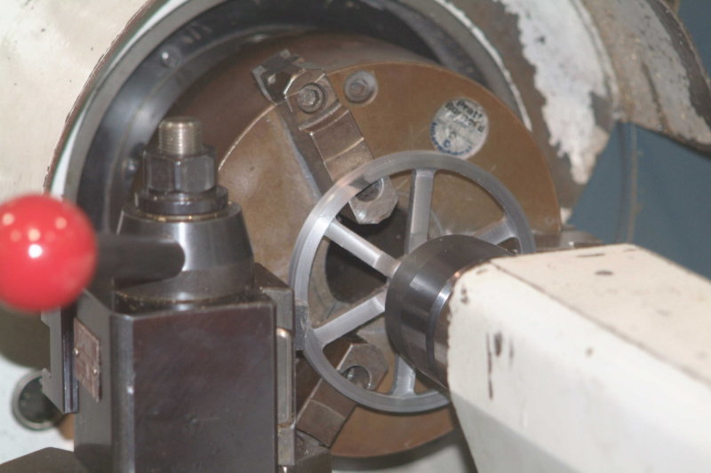
- Spoked flywheel
- avoid 90-degree edges (lots of use of rounding bits)
- eliminate visible holes and screws to the extent possible

As Guinevere sings in the musical "Camelot", "I do applaud your noble goals; now let us see if you achieve them." ;D I already have some ideas from Gail's build, and hope to plagiarize more as time goes by. :bow:

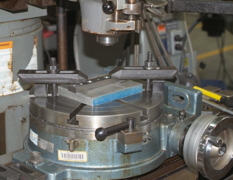
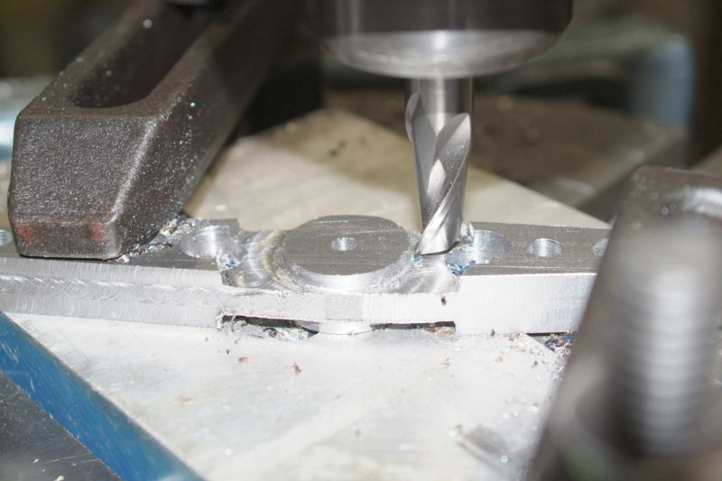
Made a small start by cutting a piece of aluminum from the scrap bin to the approximate dimension of the base, squaring the 4 sides, and flycutting the top:

large.jpg


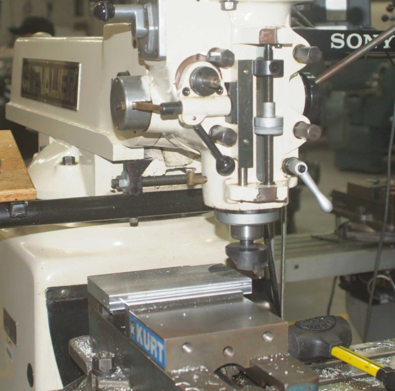
The flycutter is one I made earler as part of the shop curriculum.

 
Well you got me hooked Kirk,

I like to see what people come up with when they intend to alter the plan. Personally my favourite kind of build as you may have seen? Is the type where you change the aesthetics but keep the heart of the plan ;D ( I am crap at rigidly following the plan!)


Keep us informed,


Ralph.
 
I had a couple of hours during class to make some minor progress. I experiemented with rounding the edges on the base with a 1/16" corner rounding mill. The results weren't too bad, although the rounding is not all that obvious. I plan to see how the 1/8" mill works next time out.

I also was able to cut off a slice of 5" A2 tool steel for the flywheel (it was the only piece of round bar with the right diameter). Using reversed jaws on the chuck and a carbide cutter at low speed, I was able to face both sides to .400" thickness (will turn to final .375 later) and then bored & reamed the .500" center hole. I can't say that the finish is very good, but as I will be cutting away a good portion to make the spokes it shouldn't matter too much. I plan to use the chemical blackener on the wheel once it's machined, and may try the surface grinder on the sides of the rim for some bling. I am going to play with Marv's flywheel program and try different dimensions for the spokes.
 
I started on the flywheel last night at school. The goal is a 6-spoke version with a 1" radius hub and a .25" radius rim. Previously I had faced the blank on both sides on the lathe.

My first task was getting the big Yausa rotary table mounted on the milling table and then getting it centered under the spindle. As this was my first time it took quite a while to get the DTI set up and the table positioned.

I then centered the blank on the table by use of a 1/2" end mill in the spindle passing through the 1/2" reamed hole in the center of the blank. Then I needed to clamp it to the table, also a new experience. The t-nuts for the rotary are smaller than those for the milling table, so it took a while before I got it set up securely.

I then milled out the space between the hub and the rim 1/8" deep using a 2-flute 1/2" end mill. As the blank is A2 steel this was not a particularly fast process, making lots of nice blue chips. Turned the blank over, reclamped, and did the same on the other side.

Next I needed to drill the holes next to the rim that define the spokes. Since drilling into the rotary table would be frowned upon, I found a round piece of aluminum in the scrap box, and reclamped the wheel on top of it onto the table. I then center drilled and drilled 1/4" holes around the rim.

By then it was time to clean up for the night. I am able to leave the setup, so on Thursday I can resume where I left off. I need to drill the 12 holes around the rim, and then trepan out the material around the spokes with an end mill. Once I do that I can clamp the spokes and clean up the edge of the wheel.

I hope to take some pics next time.
 
I managed to rough out the flywheel last night. First drilled the holes defining the spoke boundaries:

large.jpg


Holes are 1/4". Then used a 1/4" 4-flute end mill to trepan the material between:

large.jpg


Given the hardness of the A2 material and the need to make 18 separate cuts, cranking the mill's handle was pretty time-consuming. Aluminum would have gone a lot faster :eek:

Next time out I'll clean up the edges of the spoked with a corner rounding mill and start on another part.

As this was my first time using the rotab, I found it a good learning experience. There are quite a few of the other parts that will use the rotab as well. Luckily there are no other students using the mills this quarter, so that I can leave setups between classes.
 
First time with a rotary :eek: Looks great!
If I can make a suggestion; I think the step blocks should be moved closer to the back of the clamps so the clamping force is more on the part and less on the blocks, but the part turned out great in tough material so I guess I should shut up now ;)
 
Looking good 8)

kvom said:
there are no other students using the mills this quarter

Useful that you can leave your set up's etc but, it's a sad reflection on education imho

CC
 
I really got to try that flywheel spokes thingy ;D Looks pretty damn good from where I'm sitting ;D


Well I'm off out to see what I can do in my little shop, not necessarily a flywheel but making some chips all the same ;D


Ralph.
 
That's a great looking flywheel :bow: Keep us posted,

Cheers,
Phil
 
This time I tried to make a finish cut on the outer rim. This was hard to do on the rotary as the rotary table slots weren't close enough to the center to enable me to clamp the wheel on the inside of the rim.

So my instructor suggested the following setup on the lathe:

large.jpg


I spaced the inner side of the wheel away from the jaws using 1/8" thick parallels, meaning that the jaws were contacting only 2/3 of the inner rim. I use the live center as a safety measure in case the wheel would come loose from the jaws (wheel has .50 center hole), and made only .01" cuts at a time until the perimeter was round..

The material is A2 tool steel, which I used becasue the school had a 5" diameter rod. Did the cuts at 170 rpm with a carbide cutter. I hand fed the carriage until the final pass, where I used the machine feed at .002/revolution, getting a nice final finish.

This material has a tendency to create burrs for every cut, so I have quite a bit of filing to do.

I tried out the 1/8" corner rounding mill on the top of my aluminum base plate. I do like the radius better than the 1/16", but these bits are finicky to position. I will need to calculate the bit's "compensation" in the XY and Z directions and use very careful indications for every setup in order to get a proper result. Last night I was working on a mill with no DRO, and being tired decided to pack it in until a mill with DRO is freed up (the other people were using the mills to finish their CXA toolholders, the first project that the beginning classes make).

On Thursday I intend to start on the beam. I was looking in the scrap bin for a suitable piece of aluminum when I chanced upon a piece of CRS that had exactly the dimensions called for (6 x 1 x .5). I will drill the holes on a mill with a vise, and then finish it on the rotary table.
 
This time I started on the beam. I learned a lot on how not to machine it, and after 4.5 hours of work was still not finished. I started by drilling the center and end holes, plus three more on each arm for "bling". I had calculated the angle of the taper (5.7 degrees) and then calculated the drill sizes for each hole so that the sizes would taper at the same rate. What I didn't realize is that the spacing should also be proportional so that the distance between each hole's edge would be the same.

I decided to leave the middle hole of the three at 1/4". It won't look as good, but drilling it out larger might be worse.

Afterwards I clamped the bar on the rotab:

large.jpg


In theory to mill the tapers, I needed to tram the edges parallel to the x-axis using a DTI, the rotate the table 5.7 degrees. Since I hadn't milled the edges of the bar, tramming took a lot longer than it should. I finally got it to .008" in 3".

The mill doesn't have a table drive, so I had to crank it quite a few times. Because of the clamps, I could cut only two of the tapers this way.

By the time I finished this a mill with a vise and table drive was open, so I cut the other two tapers using the vise and angle blocks. Much, much faster.

Then it was back to the table to cut out the center hubs:

large.jpg


What's left is to reduce the arms and round off the ends.

I imagine this part should be able to be completed in 2 hours or so, not the 5-6 hours it will end up taking me. Were I to make it again, I would:

1) drill the holes
2) Mount on the rotab and mill the center hub
3) Back to the vise/angle bars to mill the tapers
4) Back to the rotab to round the ends
5) Mill the arms to final thickness.

Aluminum would be easier as well, as milling steel leaves a lot of burrs on every edge requiring filing.

Using the rotab takes a bit of patience. Every time you need to reclamp it's necessary to change out mill/collet for a drill/collet to align the part with the center of the table, clamp it down, then change back to the mill. This part would require a minimum of 4 changes.
 
I managed to finish milling the arms of the beam to final thickness, and did a bit of filing on the resulting burrs.

I decided to try to make the two valve levers, using a slice of the mystery bronze rod that Cedge gave me when I visited a while back. The rod is 2" in diameter, so in theory I should be able to cut both levers from one piece.

I put the rod in the lathe and faced off the saw cut, then turned down about one inch to get an even disk. The material seemed to tear a fair amount, and the finish was only so-so. It might need a higher speed (lathe was at 520 rpm).

I cut off a slice about 3/8" thick, then mounted it on the rotary table and used an end mill to try to take it down to .25". Again the material tends to smear, sort of like the experience Brian had with his copper base. With such a small piece I needed to reclamp several times to cover the entire surface.

I then drilled the shaft hole, centered it on the rotab, and formed the hub. Again lots of burrs and smearing. I did drill the other .25" holes, but ran out of time before trying to finish the final form.

I have a piece of .25" thick brass plate, so next time I'm going to make the simpler 2-hole lever from it. Assuming it machines better I'll likely start over on the 3-hole lever using that material, and save the bronze for something later.
 
I somehow managed to get one simple part mostly done in only 5 hours:

large.jpg


Started with a strip of .25" thick 360 brass, squared on three edges, and then drilled the holes leaving enough material on each end to clamp on the rotary. Then for some reason. when cutting the round "relief" around the larger hole, it ended up off center. I guessed that somehow the rotab zero had shifted or the DRO coords had gotten changed. Put on the DTI and indicated the table again: showed dead on. Very confusing.

Back to the vise to cut another piece to try again. Reclamped, centered, and turned the mill around the hole with the motor off. Definitely still off center. Total confusion.

I had been using a piece of aluminum under the brass for clamping, and so switched to a piece of steel. This time it stayed centered. So the only thing I can figure is that the aluminum somehow how moved under the clamps or the pressure of the tool.

After getting the rounded ends cut out I needed to cut the side angles, which are about 5.25 degrees. I had to used the 5 degree angle block, so the sides didn't come out perfectly. The material is much thinner than the angle block, so had to exercise a bit of ingenuity to get it clamped in the vise properly. A bit of filing and polishing should get it close (did some after taking the pic, so it looks better now than then).

It's a good thing I don't have to charge myself an hourly rate making these parts. ::) I'm hoping that the 2-lobed lever can be done with less effort next week.

The brass machines a lot better than the bronze I tried last time.
 
Kvom--You're doing great. I'm enjoying seeing somebody else build "my engine". Those little brass peices can drive you nuts!!---Brian
 
Last night I managed to rough out the other lever. It still needs to be drilled and tapped for the setscrew, plus have the tooling marks polished out.

medium.jpg


Although the edge profile is a little off, the hole positions are accurate to the plan, which is the important part.

Doing the rounding bits on the big rotab with big clamps is very tedious. I believe that a "rounding table", similar to what has been shown on other threads, would have made this type of work go a lot faster. I'm inclined to believe that making this part at Elmer's original scale would have meant a lit of work with a file instead of milling everything. maybe I'm wreong about that.

The mills with vises are being used for a few weeks, so as I had some time left I decided to start on the eccentric on the lathe afterwards. I turned some 12L14 stock down to the diameters for the non-eccentric portions, intending to turn the eccentric disk by offsetting the bar using a 4-jaw chuck. This would be done next time. I haven't tried to use a 4-jaw as yet, so it would be a good learning experience. That said, I think there might be better ways to go about this.

I'm now remembering Gail's approach of turning the eccentric disk separately and attaching it via pins or screws. That would also allow a retaining outside rim to keep the rod assembly from working its way off.
 
kvom, your project looks great and things look to be coming along real nicely.
 
Yesterday I continued to try to make more brass "fiddly bits". I succeeded mainly in making scraps, but I did learn something very useful.

I cut two strips of brass from a .25" thick piece of brass wanting to make the straps that connect the levers to the beam. The plans call for them to be .06" thick, posing a problem on how to machine to this thickness. I thought I would need to clamp these to the mill table and machine them in a couple of passes, but the instructor introduced me to the concept of soft jaws for the Kurt vise.

So I removed the two steel jaws and bolted in the aluminum ones. Then I clamped a 1/8" parallel between them and machined a slot 1/4" wide and .05 deep centered on the gap. With the parallel removed I could clamp the strips within the resulting notch. Worked a charm. I will take some pics during the next session. The design of the Kurt vise makes mounting these jaws fairly easy. To do the same on my Bridgeport vise will be a bit more difficult as the hard jaws are attached with threaded hole from the rear.

Although I succeeded making nicely machined thin strips I found that I should have machined the end radii beforehand, as the strips bent when I attempted it afterwards.
 
To do the same on my Bridgeport vise will be a bit more difficult as the hard jaws are attached with threaded hole from the rear.

Although more convenient, there's no reason that soft jaws have to be attached to the vise. I have a collection of 1/4" thick aluminum "parallels" with various steps machined into them that serve as removable soft jaws.

Although I succeeded making nicely machined thin strips I found that I should have machined the end radii beforehand, as the strips bent when I attempted it afterwards.

Instead of machining the radii, (rotary) file or sand them. You might want to take a look at my rounding over jig built for this purpose.

http://www.schsm.com/html/marv_klotz_38.html
 
Good points as always, Marv.

A rounding jig is clearly more convenient for these parts than a rotab, and I will likely try to build one when my home shop is operational. Since the brass is .25" thick and I have a .125" corner rounding bit, it's quick quick for me to use in this situation.

I don't own a rotary file; need to look for one I guess.
 
Back
Top