arnoldb
Well-Known Member
- Joined
- Apr 8, 2009
- Messages
- 1,792
- Reaction score
- 12
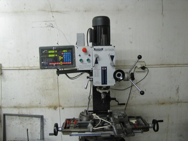
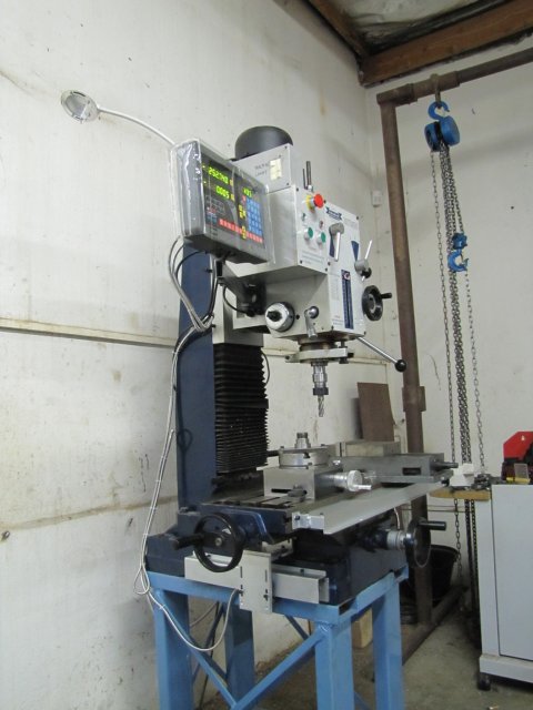
When I bought my mill two years ago, I commented that I'd get a DRO in my dreams.
Dreams do come true sometimes ;D - it takes a bit of planning, budgeting, a bit of hard work and a stroke of good luck. And a supplier who's willing to ship to a way-out location at a fair price.
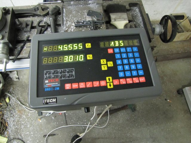
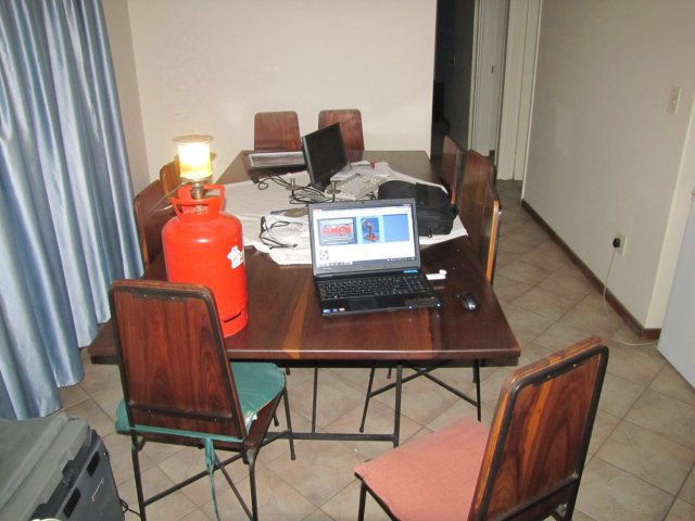
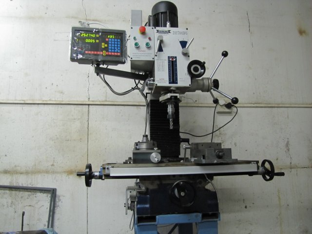
Some weeks ago, I had a little windfall, and I decided to treat myself a bit. After watching currency exchange rates for a while and seeing a good opportunity, I pounced and ordered a two-axis DRO from TheDROStore.com. Scott there gave me great service, and a week and a half ago, this lot landed on my freezer after feverish unpacking") :
:
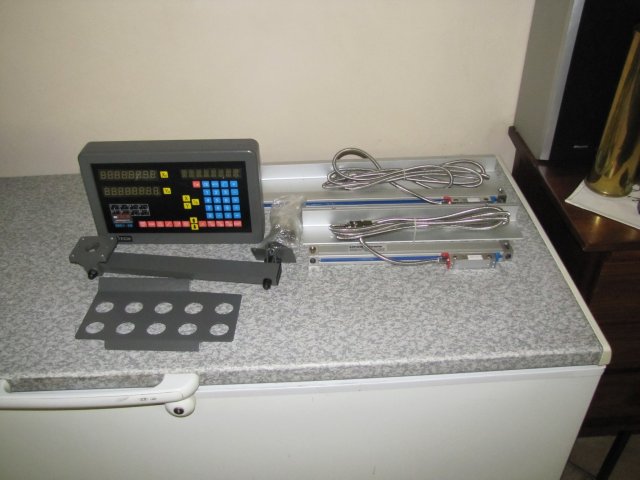
A three-axis unit would be nice - in fact, if I had a knee mill I would have spent the extra money for a three-axis unit. My mill is not really suited for DRO on the Z axis - so there's not much to be gained for spending the additional money.
Yesterday morning I was awakened to a phone ringing - that call turned into an excursion to one of my new work sites to sort out a crisis, but I got home by lunch time and started work on installing the DRO
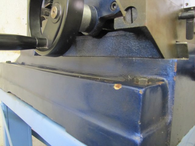
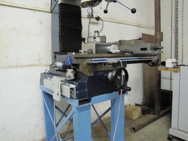
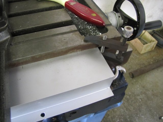
Easy part first, I thought... The X axis scale. It would have been nice to install it at the back of the table, but that would mean I'd lose about an inch of travel in the Y axis - no good, as I do use that travel once in a while. So on the front it has to go, but things were a bit tight for a conventional install, as the installation holes would be a bit awkward - wanting to break into the T-slot on the side of the table, things would interfere a bit with the locking screws which I use a lot, and the cover plate supplied wouldn't even fit without sticking up past the table's edge:
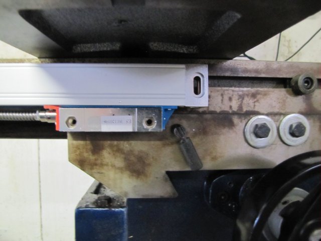
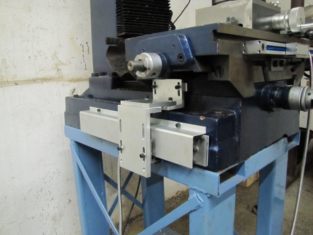
Installing it on-edge seemed a bit more sensible - though I'd have to make sure to add a bit more protection for the overhang:
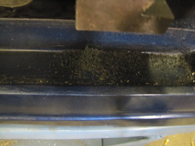
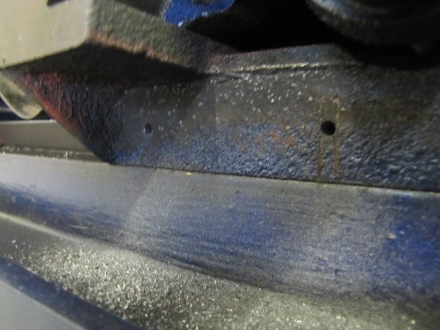
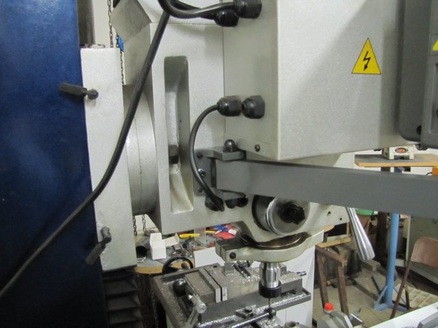
The reader could be mounted where the table stop used to be mounted; I've never used the table stop; the only use for its mounting holes for me have been to cobble together a crude DRO using a digital caliper when I built the Coomber engines. The one mounting hole is a whopping 1mm lower than the other:
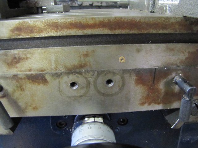
The DRO would also sit over the oiler hole in the photo, but that's not a problem, as I don't use that to oil the table; I just apply way oil to the ways from the bottom and work that through by traversing the table a couple of times.
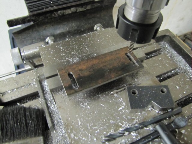
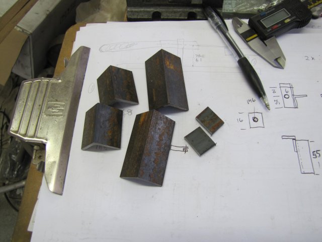
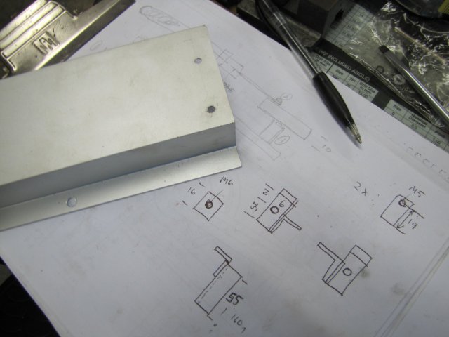
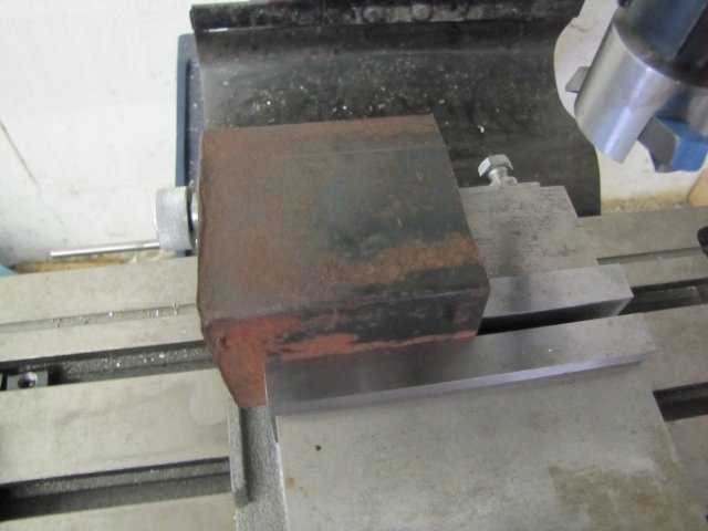
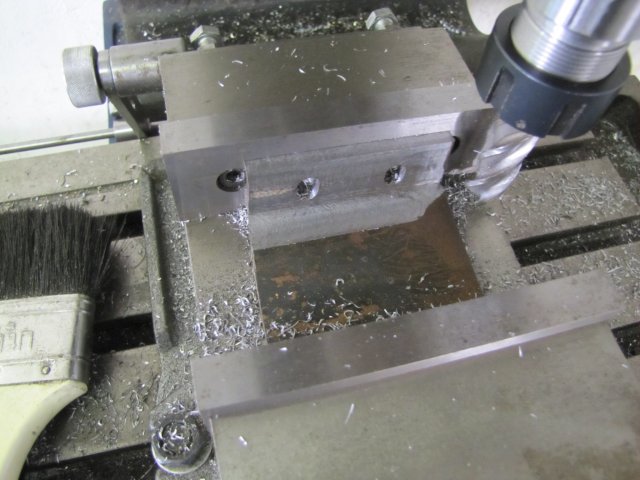
Needing a mount for the reader head, I rummaged through the scrap pile; the only suitable bit I could find was a section of angle iron that was cut with a guillotine (shear?) on the one side and a bit deformed there. So I set it up for some clean-up:
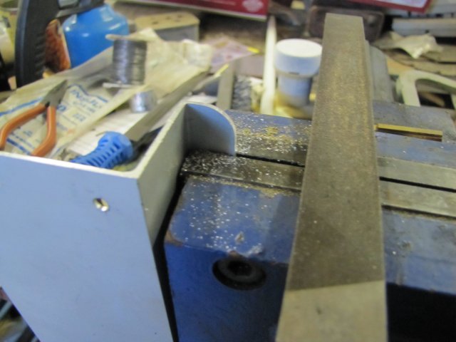
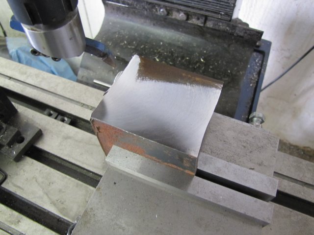
A quick fly-cut - showing just how much it was deformed:
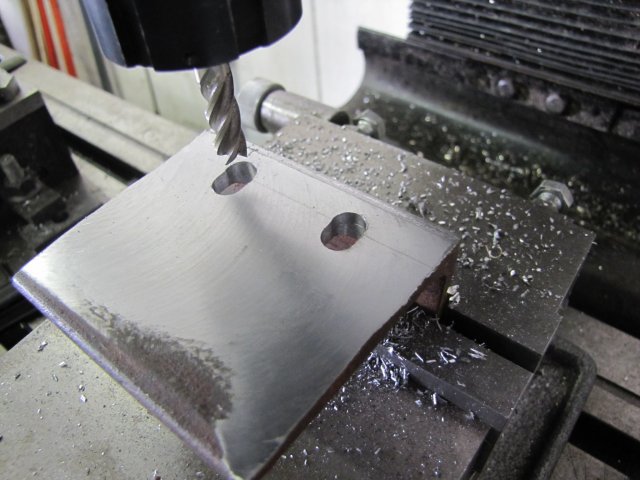
After a bit more work to square it up and so on, it ended up with some short 8mm slots to allow for adjustment - and compensation for the low mounting hole mentioned earlier:
I had to clean off the inside of the angle a bit as well, as the normal rounded corner would interfere with the bolt heads:
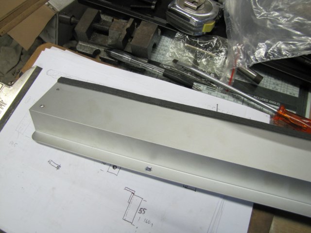
Finally done; not pretty, but practical and faced and squared up where needed:
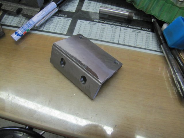
The slight cut-out I milled away above the short slots is for clearance for the mill table once installed.
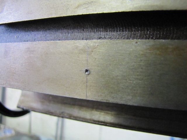
Next I marked and center punched the locations for the installation holes on the side of the table. As I'd be using a hand-held power drill, I really gave it a good whack to ensure good starting points for the drill:
I then drilled the spots 4.2mm and tapped them M5 - no drama there; the cast iron drilled and tapped easily.
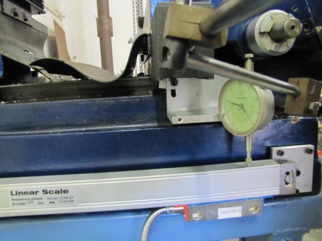
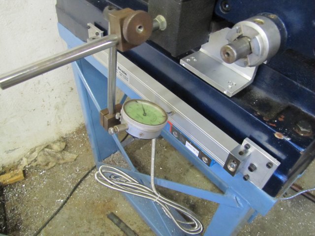
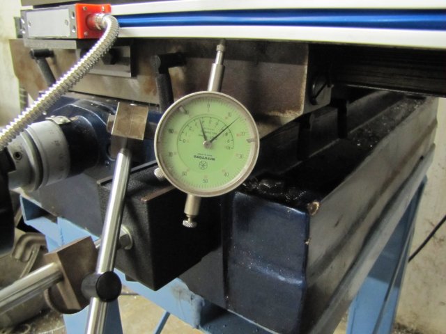
Then I mounted the X scale and a dial indicator using a magnetic base, and started to tram in the scale. The installation instructions state that the scale needs to travel with at most 0.02mm (1 thou) run-out, but the DI was at a bit of an angle, I went all the way to get it dead-nuts with no deflection across the scale's travel:
I nearly went cranky there; cranking the mill table over about 15 times full-travel gets to be seriously hard work :big: - it's time I built a power feed!
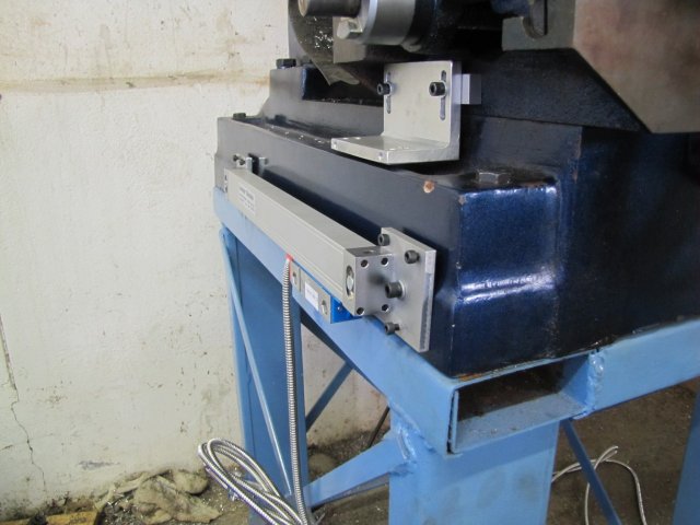
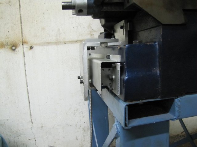
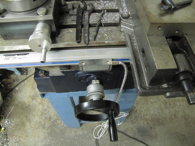
Finally the X axis scale installation was done:
My shop session yesterday was pleasantly interrupted by a shop visit. A local bloke had heard about my shop and escapades on the grapevine, and came over for a bit of a look-see and gum-bashing session; He's interested in setting up a home shop too, and while he does not seem overly interested in building model engines, he is interested in other home machining projects. It's really nice to get a shop visit!
To be continued...
Regards, Arnold
Dreams do come true sometimes ;D - it takes a bit of planning, budgeting, a bit of hard work and a stroke of good luck. And a supplier who's willing to ship to a way-out location at a fair price.
Some weeks ago, I had a little windfall, and I decided to treat myself a bit. After watching currency exchange rates for a while and seeing a good opportunity, I pounced and ordered a two-axis DRO from TheDROStore.com. Scott there gave me great service, and a week and a half ago, this lot landed on my freezer after feverish unpacking
:
A three-axis unit would be nice - in fact, if I had a knee mill I would have spent the extra money for a three-axis unit. My mill is not really suited for DRO on the Z axis - so there's not much to be gained for spending the additional money.
Yesterday morning I was awakened to a phone ringing - that call turned into an excursion to one of my new work sites to sort out a crisis, but I got home by lunch time and started work on installing the DRO
Easy part first, I thought... The X axis scale. It would have been nice to install it at the back of the table, but that would mean I'd lose about an inch of travel in the Y axis - no good, as I do use that travel once in a while. So on the front it has to go, but things were a bit tight for a conventional install, as the installation holes would be a bit awkward - wanting to break into the T-slot on the side of the table, things would interfere a bit with the locking screws which I use a lot, and the cover plate supplied wouldn't even fit without sticking up past the table's edge:
Installing it on-edge seemed a bit more sensible - though I'd have to make sure to add a bit more protection for the overhang:
The reader could be mounted where the table stop used to be mounted; I've never used the table stop; the only use for its mounting holes for me have been to cobble together a crude DRO using a digital caliper when I built the Coomber engines. The one mounting hole is a whopping 1mm lower than the other:
The DRO would also sit over the oiler hole in the photo, but that's not a problem, as I don't use that to oil the table; I just apply way oil to the ways from the bottom and work that through by traversing the table a couple of times.
Needing a mount for the reader head, I rummaged through the scrap pile; the only suitable bit I could find was a section of angle iron that was cut with a guillotine (shear?) on the one side and a bit deformed there. So I set it up for some clean-up:
A quick fly-cut - showing just how much it was deformed:
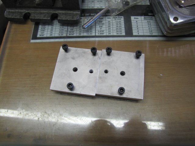
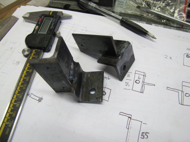
After a bit more work to square it up and so on, it ended up with some short 8mm slots to allow for adjustment - and compensation for the low mounting hole mentioned earlier:
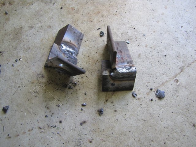
I had to clean off the inside of the angle a bit as well, as the normal rounded corner would interfere with the bolt heads:
Finally done; not pretty, but practical and faced and squared up where needed:
The slight cut-out I milled away above the short slots is for clearance for the mill table once installed.
Next I marked and center punched the locations for the installation holes on the side of the table. As I'd be using a hand-held power drill, I really gave it a good whack to ensure good starting points for the drill:
I then drilled the spots 4.2mm and tapped them M5 - no drama there; the cast iron drilled and tapped easily.
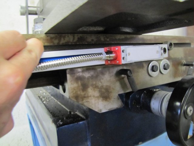
Then I mounted the X scale and a dial indicator using a magnetic base, and started to tram in the scale. The installation instructions state that the scale needs to travel with at most 0.02mm (1 thou) run-out, but the DI was at a bit of an angle, I went all the way to get it dead-nuts with no deflection across the scale's travel:
I nearly went cranky there; cranking the mill table over about 15 times full-travel gets to be seriously hard work :big: - it's time I built a power feed!
Finally the X axis scale installation was done:
My shop session yesterday was pleasantly interrupted by a shop visit. A local bloke had heard about my shop and escapades on the grapevine, and came over for a bit of a look-see and gum-bashing session; He's interested in setting up a home shop too, and while he does not seem overly interested in building model engines, he is interested in other home machining projects. It's really nice to get a shop visit!
To be continued...
Regards, Arnold