module 1 gear cutter question

Home Model Engine Machinist Forum

Help Support Home Model Engine Machinist Forum:

This site may earn a commission from merchant affiliate links, including eBay, Amazon, and others.

werowance

Well-Known Member
HMEM Supporting Member
Joined
Sep 2, 2011
Messages
1,341
Reaction score
360
i know i have asked several questions about gear cutters in the past but today i stumbled across some information that if i understand correctly will make my life much easier.

in particular i only want to work with module 1 for my question because thats about the only thing i use.

so if i have a 50 tooth gear i want to cut with module 1 then the gear blank outside dia would be 52 mm right? just add 2 mm to the number of teeth you want to get the outside gear blank.

then on total depth of cut - the bottom of the "V" between each tooth. all you do for a 50 tooth is subtract 2 mm from the number of teeth for 48 mm dia measured from bottom v to bottom v on the other side right?

in other words +2 mm over the number of teeth for gear blank dia
and depth of cut is 2mm deep for all module 1 cuts.
the magic number is 2mm

if this info is correct then it makes my life much easier on calculating module 1 gears
 
No Addendum is 1 x MOD and dedendum 1.4 x MOD so total depth is 2.4 x MOD
 
ok, so "addendum" is the total outside diameter of the blank before cutting teeth?
and dedendum is the total depth or bottom of the groove?
 
i found the answer to addendum and dedendum.

and for easy remembering for me, since for now i will be using module 1 only. then each cut per tooth should be 2.4 deep as measured by touching cutter to outside of blank and then moving in by 2.4mm as the total depth of cut - this goes for every gear tooth range i can cut right? in other words any module 1 gear i make will be 2.4mm deep?
 
now, where or how to calculate the tooth spacing on a rack gear in mod 1? as in distance between each tooth cut? pretty easy to do on round gears with a rotary table but about to attempt my first rack gear ever.
 
That's it 2.4mm deep from when the cutter touches the 1MOD or finer gears

For MOD racks pitch = MOD x Pi

So for your MOD1 Pitch = 1 x 3.14159mm
 
Jasonb. I have changed my spreadsheet to use your 1.4 for module 1 or less and it will change to 1.25 above module 1. It is a small change but I think that it will be good for my 0.5 module gears.
I made this spread sheet because it is simple and doesn't give a heap of values for things that you don't need to know. of course it is only good if you buy ready made cutters.
For anyone new to cutting gears one thing i will say is that accuracy is very important. I use a mandrel in the chuck of a rotary table, The mandrel should be a good tight fit and it is important to finish the blank to final size on the mandrel. be very careful putting it into the chuck and check with a dial gauge. particularly when using module 0.5 even a small error can be a lot of tooth height.
 

Attachments

  • gearcutting.xls
    7.5 KB · Views: 165
I use the web site for Helical Gears which actually has an extensive technical information. Gears will be locked up if they are cut to the ideal dimensions and placed at the ideal center distance, add the pitch diameters. In practice the distance between centers is increased, the added distance times the sine of the pitch angle, the table on back lash is calculated for my guess a 20 degree angle. Will be different for a 14.5 angle. The center difference in a planetary gear set or any gear set with and ring gear, teeth cut into the ID of a bore can not be changed from the ideal. The solution is to in effect cut the teeth deeper, this changes the pitch angle at the ideal contact point of the two pitch circles. Trigonometry, can calculate the clearance with the change in angle. These calculations are provided by in the technical information. https://www.hpcgears.com/pdf_c33/27.48-27.60.pdf PS I was handed a gear sent cut at the ideal shape and placed at the ideal distance because one of the gears was a ring. LOCKED UP. My employer had a sand blaster which I used to wear down the teeth so they had clearance.
 
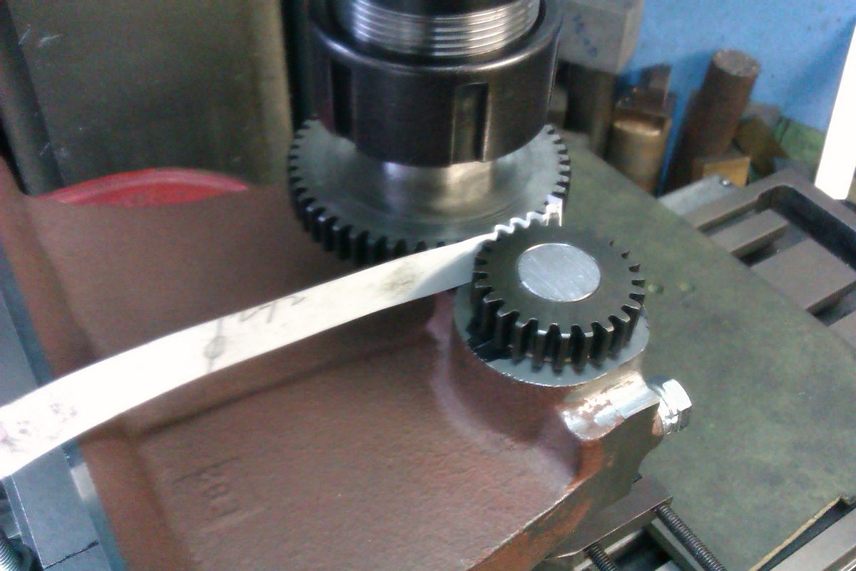
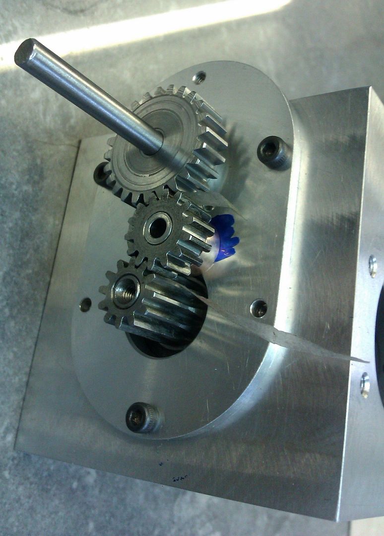
For our one off engines the easiest way to get the gears running freely is to gap them on the machine before drilling/reaming the hole. I usually fit the crankshaft of some crankshaft material to the engine and then have the other gear on a piece of rod held in the collet chuck and slip a piece of paper between them while rotating by hand and adjusting the X-Y postion. once happy with how they fit lock the table and change to your drill/reamer. That way even if you nave not cut the gears to exact spec they will run OK.

IMAG3636_zps24ncn1th.jpg

IMAG3002_zpsebkpryci.jpg


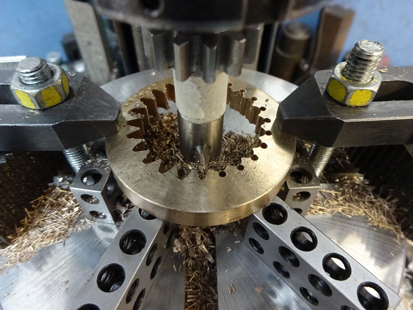
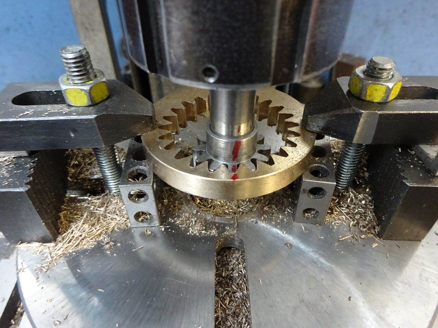
Same sort of thing when cutting internal gears, mount the sproket on teh arbout holding the cutter then you can slide it down to check the mesh and if needed take a little more off the inner teeth without loosing the set up

DSC02459_zps77si4daf.jpg

DSC02460_zpskxsmpo2q.jpg
 

Latest posts

Back
Top