Modifying my Home Built Tool & Cutter Grinder

Home Model Engine Machinist Forum

Help Support Home Model Engine Machinist Forum:

This site may earn a commission from merchant affiliate links, including eBay, Amazon, and others.

cfellows

Well-Known Member
Project of the Month Winner
Joined
Aug 25, 2007
Messages
3,890
Reaction score
715
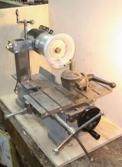
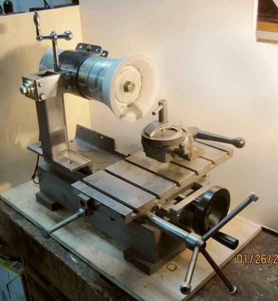
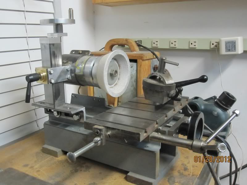
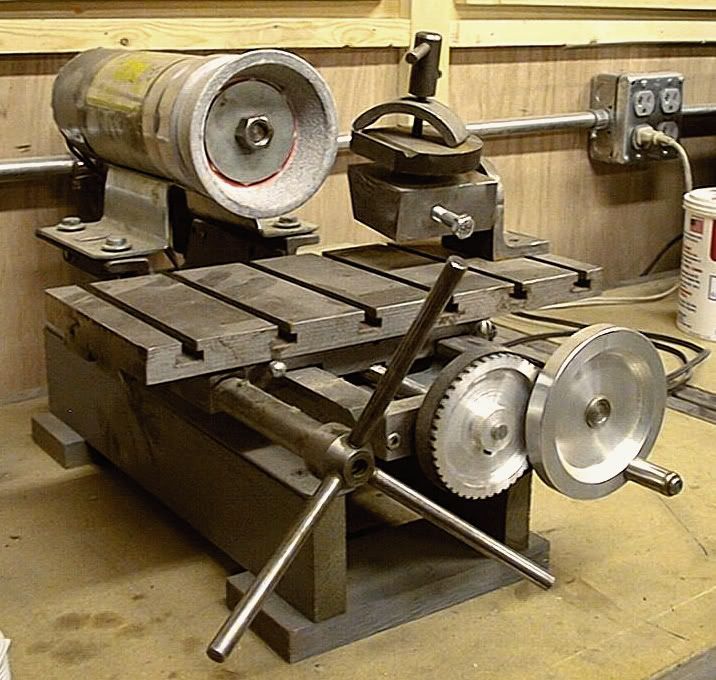
This is my home built tool & cutter grinder...


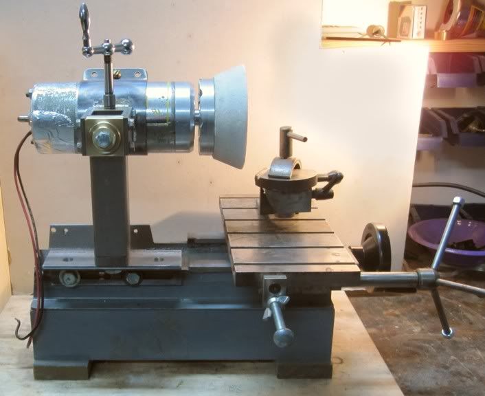
And here are some more pictures as I'm tearing it down...
033dfb6f.jpg


033dfb6f.jpg


6d5063cc.jpg


7fd77e99.jpg


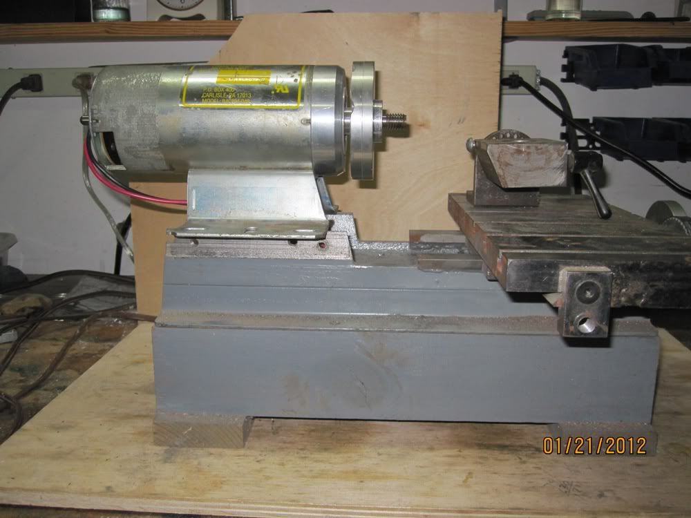
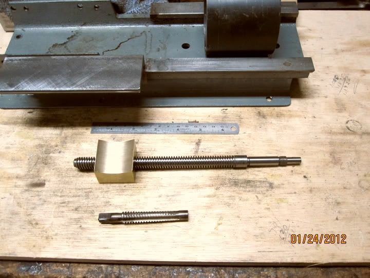
It's made from 4" channel iron and a 5,000 RPM treadmill duty motor with a variac to adjust the speed. I rebuilt the front bearing carrier on the motor from aluminum to increase the accuracy and seal the motor from grinding dust. There is no air flow through the motor but so far it has never overheated. The motor has ball bearings on front and back and runs very quietly with virtually no vibration. I rarely run it more than half speed and have never put any appreciable load on it. I have several spindle attachments for it that allows me to use an assortment of different grind stones.

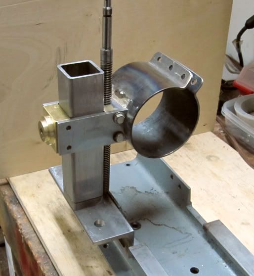
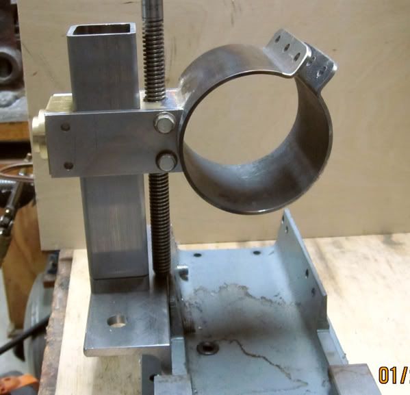
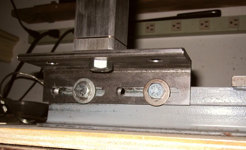
The grinder has served me well and is reasonably accurate, but is somewhat deficient in user friendlieness. The motor is fixed solidly to the frame and all angle and height adjustments must be made on the work holder attached to the table. I've long been contemplating modifications which would let me adjust the height of the spindle as well as the overhang of the grind stone over the table. So, that's what this thread is about.

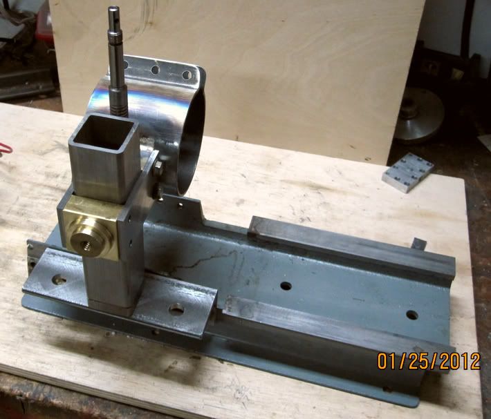
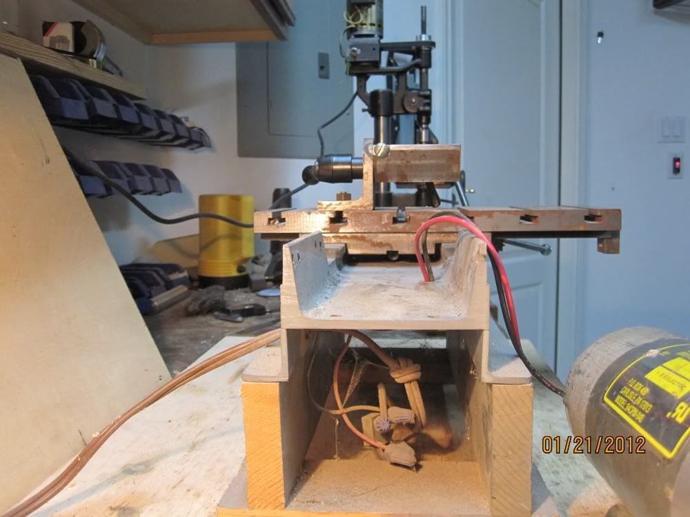
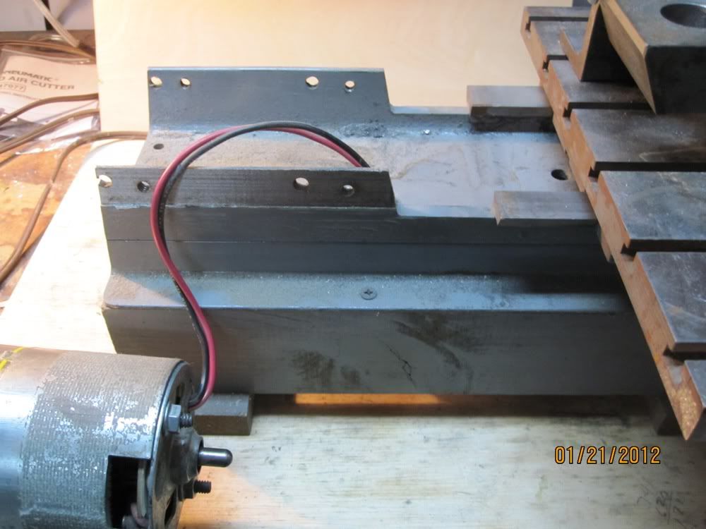
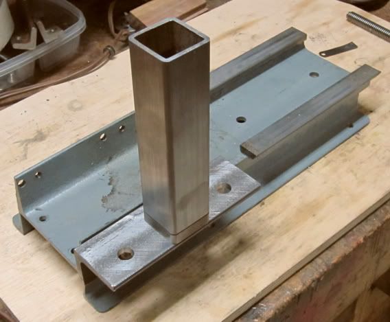
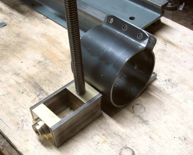
Here you can see the 1/4" thick angle iron I added to the side for mounting the vertical column which will carry the motor. The angle iron has two slots that allow it to slide forward and back by about 2 3/8" inches which will give me more or less overhang over the table.

More pictures to come...

Chuck
 
Last edited by a moderator:
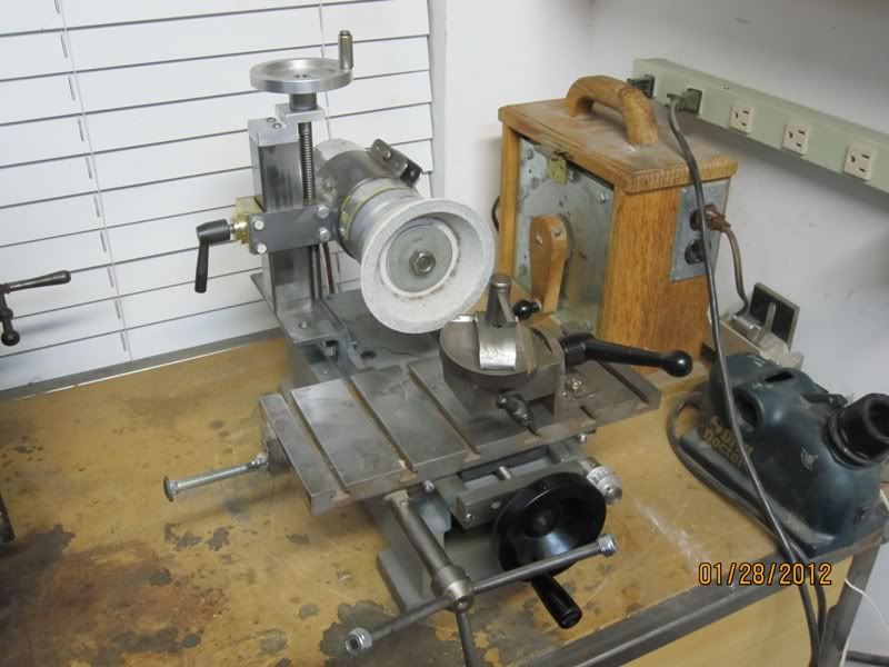
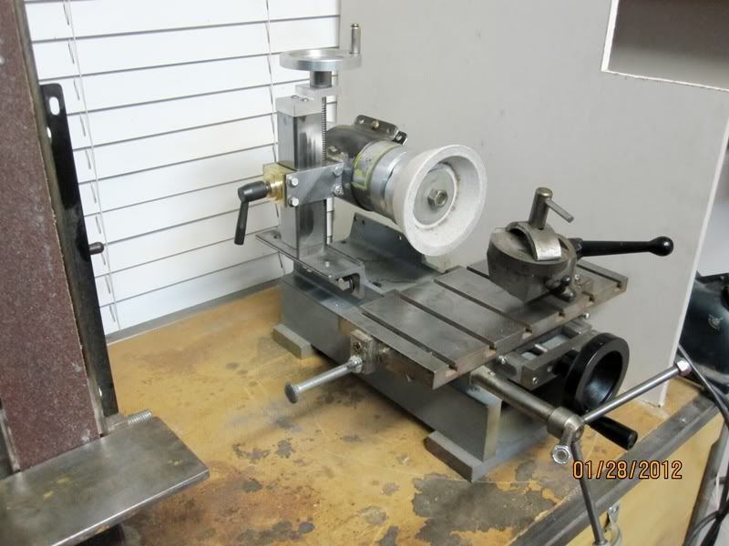
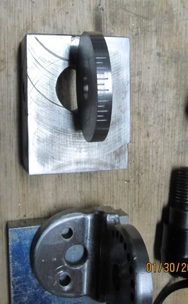
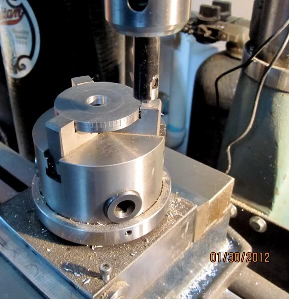
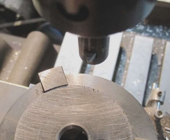
This first picture shows how the column which holds the motor attaches to the base. I have 3 holes in the angle iron platform so the column can be mounted in the middle or on either end for moving the motor forward and back.

5da697e0.jpg


Here is a view underneath the column platform. It's slotted to allow forward and aft adjustment by about 2 inches. There are also two sets of holes which allow further adjustment forward and back.

4e120cd3.jpg


Do you get the idea that I want a lot of forward and backward positioning of the motor / grindstone????

Here is the motor clamp that I fashioned from 1/8" thick steel sheet.

6a0d8f5d.jpg


And here is what the motor holding assembly will look like.

63041c3c.jpg


Chuck
 
Looks real good cfellows, ;) I am working on an idea for a tool grinder made with a Harbor Freight 3in1 mill/lathe I picked up cheap. I felt that it would cover vertical & horizontal position of the grind wheel ;)
I see some good ideas with what you are doing so will be watching for further installments :big:
 
Thanks, here are some pictures with parts temporarily hung in place.

562aaa02.jpg


2a895ab6.jpg


1802deb6.jpg


Think I'm getting close to being able to put this thing back together. Tomorrow I will remove the metal feet from the motor so it will fit in the ring clamp I made. That will be the point of no return.

Chuck
 
Chuck,
Is there a build thread on the origional? I have a treadmill motor like yours looking for a new purpose.

Chuck in E. TN
 
RexL said:
Um, how'd you form the motor clamp?

I started with a flat strip of steel, about .110" thick by 3" wide and 10" long. I used my (home made) press brake in my (home made) 20 ton hydraulic press to fold the tabs on each end. Then I laid the strip down across a 3" piece of channel iron with the flat part on the bottom. I put a 3" diameter billet of aluminum rod on top of the strip, then used my hydraulic press to push the billet down on the strip forcing it into the channel iron and making it curl up around the billet. Then I continued to use the press to finish forming the ring around the billet. I should've made a video or at least took some pictures! :doh:

Chuck
 
chucketn said:
Chuck,
Is there a build thread on the origional? I have a treadmill motor like yours looking for a new purpose.

Chuck in E. TN

No, sorry, Chuck. I built that cutter grinder a number of years ago before HMEM was even a twinkle in Rick's eyes. I have some drawings which I can probably clean up. The main frame is made from a piece of 4" channel iron about 14" long. I milled the sides down on the front of the channel iron then welded a piece of 1" x 1/4" cold rolled steel on each side to form the y axis ways. I then used a mill to true up the surface and cut the 60 degree sides to form the dovetails. The y-axis block was milled from a piece of 3/4" thick cold rolled steel. The table was milled from a piece of 6" x 11" x 1" cold rolled steel. I milled an integral dovetail into the back of the table and also milled a slot for a 24 pitch rack to fit in so the x-axis would use rack and pinion movement instead of a screw. There was a ton of milling done to form the dovetails and cutting the T-Slots was a very slow, painful process. It was during the building of this cutter grinder that I made a power feed for the x-axis on my mill/drill! If I had it all to do again, I would probably try to adapt an existing x-y table or at least make it out of cast iron instead of steel.

Chuck
 
I'm in the home stretch now. I've pretty much got everything reassembled. I still have to complete the crank assembly at the top of the z-axis. That crank on top of the z-axis lead screw is just sitting there, not attached. And I have to solder the motor connections back onto the switch, which is reversible, by the way.

82caf1ea.jpg


cb7d8a97.jpg


1016c4b5.jpg


I'm quite pleased with the rigidity of the column and motor assembly. I don't believe there will be any flex or vibration.

Chuck
 
Looks good Chuck I keep telling myself I need to build some thing like that but I just keep getting side tracked by other builds. I have been collecting data and examples so I'll have some place to start with.
 
cfellows said:
... and a 5,000 RPM treadmill duty motor with a variac to adjust the speed. Chuck

Nice machine! What does 'treadmill duty' mean? Is variable speed important for a T&C grinder? Is the intent to raise rpm over what say a typical bench grinder motor would provide for smaller diameter cup wheels for example. Or reduce it for some reason?

I was looking at surplus motors, daydreaming about building something similar one day. The motor prices varied all over the map, some quite expensive. This got me wondering if it wasn't more cost effective to just buy a conventional, small duty bench grinder & gut it for its motor. You can get one like this for 50$ new. Is maybe the quality of off-shore bearings not suitable for a T&C application?

2012-01-27_182114.jpg
 
petertha said:
Nice machine! What does 'treadmill duty' mean? Is variable speed important for a T&C grinder? Is the intent to raise rpm over what say a typical bench grinder motor would provide for smaller diameter cup wheels for example. Or reduce it for some reason?

I was looking at surplus motors, daydreaming about building something similar one day. The motor prices varied all over the map, some quite expensive. This got me wondering if it wasn't more cost effective to just buy a conventional, small duty bench grinder & gut it for its motor. You can get one like this for 50$ new. Is maybe the quality of off-shore bearings not suitable for a T&C application?

I'm not sure what treadmill duty means other than the motor's were originally manufactured for use in a treadmill. The are rated for up to 90 volts DC although I've run mine up to 115 volts DC. The bearings in mine seem very quiet and smooth although I can't speak for others on the market. Mine has never overheated even though I have the air vents blocked. Of course, I seldom run it for more than 15 minutes at a time. The variable speed is important because different size and type of grindstones are rated for different speeds. Some of my 4 and 5 inch wheels are only rated to 3400 RPM while the smaller cup wheels are rated higher. If you have a slower speed motor, you could probably run all your stones at the slower speed but they might not cut as fast or as smooth.

Chuck
 
It looks great Chuck! Are you going to make an end mill fixture for it?

Dave
 
Great grinder setup Chuck. Look on ebay there were some guys selling Uni-Grind universal grinder holder. I got one, $60 these are new units made in USA maybe went out of business. With those slots an easy and very rigid mount.
 
steamer said:
It looks great Chuck! Are you going to make an end mill fixture for it?

Dave

Thanks, Dave, I already have an air bearing fixture I built for grinding the flutes. I'll post some pictures of it later.

kuhncw said:
Chuck, that is a nice grinder you've built. How is the piece on the bottom of the column attached to the column. I see a slight gap at the joint.

Thanks.

Chuck

Thanks, Chuck. There isn't really a gap. I ground a slight bevel around the bottom of the column in anticipation of silver soldering the steel bottom onto the column. However, once I pressed the shouldered down part into the column, it was such a tight fit I decided I didn't need to solder it. The part extending up into the column is 3/8" long and I had to use a 24" long tommy bar on my 20 ton press to get it all the way in. The wall thickness on the column, by the way, is .120".
 
I've got the grinder pretty much finished to the point where I've put it back in it's home spot, ready to go to work.

I've got to change out the crank handle on the y-axis since it interferes with the x-axis handle. I'm waiting delivery of a small timing belt which I will use to connect the lead screw to the handle after moving it a couple of inches to the right... the way it was before!

I finished the z-axis crank assembly on top of the column and re-purposed the tool post tightening lever from my mini lathe to now serve as the clamp screw for the motor assembly to the column.

94f6a6dc.jpg


huck
de1eea4c.jpg


2ce62806.jpg


Next I'll be looking at some different tool holding fixtures to see if I can improve on what I've got...

Chuck
 
I'm beginning work on updating my existing grinding fixture and perhaps adding some new ones. The first thing I did was spiffy up the piece of angle iron that attaches the fixture to the base. I radiused the side and the base and rounded over the outside edges. After 40 years or more of working around metal I'm finally learning to remove as many of the sharp corners and edges as feasible because sooner or later I'm going to bang my hand against one of them.

Here's the base attachment and a steel disk with newly scribed graduations. This will be part of the horizontal angle adjustment and has 5 degree and 10 degree graduations.

56e7686b.jpg


Here is the setup in my mill drill for cutting the graduations. The disk is mounted on my smaller rotary table. Each full revolution of the crank handle rotates the disk 5 degrees. The scribing tool is just a boring bar that takes 3/16" square high speed tool bits. The tool cuts on the upstroke which makes the inside end neater and the bit of metal that is removed comes out on the edge which is easier and cleaner to remove.

c332c73e.jpg


This is a closeup of the boring bar and the 3/16" tool bit. You can see that it is ground to a sharp point with the cutting edge on top.

68d89243.jpg


Hopefully this will all make more sense as I get it put together.

Chuck
 
Hi Chuck, Very nice grinder you have made there! Love the base you have made, could have been made in a factory :bow: .
I am in the phase too to make some jigs, I just posted (Tacchella tread) an idea of a universal jig for cutters, drills and radius tools. Your opinion on this would be very much appreciated.
Keep on the good work and I am eager to see your progress!

Regards Jeroen
 
Back
Top