Model of a Bessemer Hot Tube Oil Field Engine

Home Model Engine Machinist Forum

Help Support Home Model Engine Machinist Forum:

This site may earn a commission from merchant affiliate links, including eBay, Amazon, and others.
Can't wait for the video on this engine Chuck. I know it is going to sound great. You sure are doing an excellent job just like you always do.

Lonnie
 
Chuck- since your cylinder is a piece of thick tubing, have you considered milling a slot on the underside of the cylinder to form the transfer port. After you get the entrance holes to the cylinder, you could braze or solder a cover piece on and take a skim cut on the entire cylinder OD. Still, it will be interesting to see this uniflow scavenged design of yours run. I'll have to see Jan's pics of his... Great build, keep the progress pix coming. MM
 
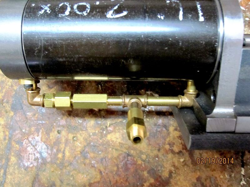
Thanks, Lonnie, MM. I had considered different ways to build the transfer port into the cylinder, but then decided on Jan Ridder's concept so I could get by with one less hole to drill in the cylinder. Lots of new ground for me with this engine, so I'm more than a little concerned about my ability to get it running.

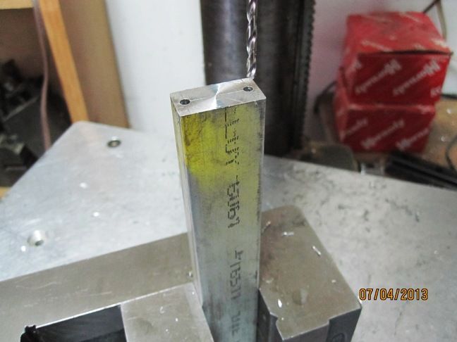
Got the connecting rod well under way this evening. After I got the material for the connecting rod cut to size (6.125" x 1" x 0.5") and marked up, I first drilled the holes in the end which will house the rod cap screws. This was done on my drill press with the rod blank clamped on end in my drill press vice.

IMG_2843_zpsc667b627.jpg


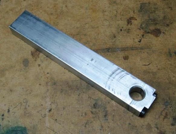
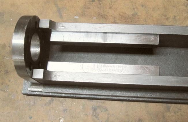
Unfortunately I forgot to take pictures of the next few steps, but, after drilling the holes in the end, I cut the rod cap loose from the connecting rod. I then shaped the rod cap and drilled out the holes. Next I tapped the connecting rod, then re-fastened the rod cap to the rod with screws. Then it's off to the mill/drill to bore the 1/2" hole for the big end of the connecting rod.

IMG_2844_zps1c3f0078.jpg


Next I drilled the 1/4" hole for the small end of the connecting rod.

IMG_2846_zpsb3f48656.jpg


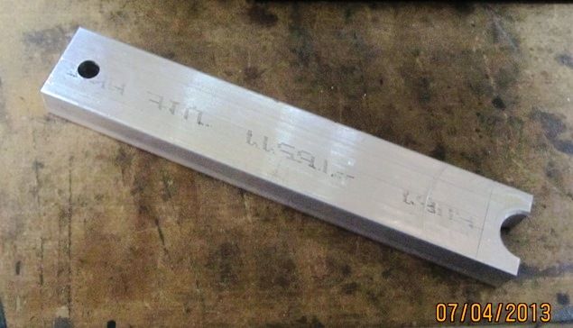
Next I used a 1/2" end mill and plunge cut both ends of the narrow portion of the rod.

IMG_2847_zpsa8e9edeb.jpg


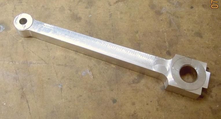
Then I cleaned out the waste between the end-cuts. Tomorrow, if the spouse doesn't find something better (in her mind) for me to do, I'll finish up the connecting rod.

Chuck
 
So, here's the finished connecting rod. It has a few dings on the bottom side since my work holding set-up wasn't quite up to the task... actually, it would have been fine if I'd simply tightened the vise handle before I started milling! :embarassed:

IMG_2849_zps22ae8f30.jpg


And here's a few shots of the engine mostly assembled.

IMG_2850_zpsd30b5b19.jpg


IMG_2852_zps9f6f29aa.jpg


IMG_2853_zps357c1f42.jpg


IMG_2854_zps8760266c.jpg


Chuck
 
Chuck--That is one very slick looking engine. I really hope it runs as good as it looks. You continue to be an inspiration to me.---Brian
 
Thanks, Brian, for the kind words. I had to backtrack a little. I mis-measured somewhere along the line and had to move the cross-head guides back a quarter of an inch. Not a trivial task for me since I had to get them at just the right height and perfectly parallel to the cylinder.

IMG_2867_zps400652ce.jpg


After getting that sorted out, I went ahead and made the adjustable piece that goes into the packing gland to compress the packing string.

IMG_2869_zps681ce01a.jpg


I ordered some more graphite string today. A fellow at G.E.A.R.S. last fall gave me a length of it, but I have no idea where I put it. Sure it will turn up again after I no longer need it.

Chuck
 
I've been watching this thread for some time now- has there been any progress on this engine or has is been shelved for some unfortunate reason?
 
Yeah, I had set it aside for some other projects I preferred to work on. I do want to finish it and I'm thinking I'll get back to it soon as I finish my vertical single 4 stroke engine.

Chuck
 
Yeah, I had set it aside for some other projects I preferred to work on. I do want to finish it and I'm thinking I'll get back to it soon as I finish my vertical single 4 stroke engine.

Chuck

Thanks. I'll be looking for it- I have wanted to build a hot-bulb engine but could never figure out the fuel delivery or cylinder head.
 
I'm waiting on some parts for my propane fuel project, so I'm pulling the Bessemer project off the shelf, dusting it off and evaluating where I am with it. Today I finished fitting the fuel transfer plumbing to the cylinder and head.

IMG_3413_zpsd82eb2dc.jpg


IMG_3414_zpsbaaed11b.jpg


If you recall, I'm using Jan Ridders pressure controlled fuel transfer design. I will likely have to make some adjustments to seal up all the leaks and am more than a little worried about how well I'll be able to get that done. I did buy some graphite string to pack the gland around the piston rod. I'm also a little concerned about the fact that I don't plan to use a piston ring since that gets pretty complicated on 2 stroke engines.

I'm also planning to try a glow plug first since I've had pretty good luck with that on my plumbing parts engine. It also obviates the need for points.

The next thing I'll complete is the taper collet to secure the flywheel to the crankshaft. Then we'll see where I go from there.

Chuck
 
Got the flywheel cone collet nearly finished. I started with a piece of 1.5" round rod and shouldered down the end. The spigot is 1 5/16" long, which is the thickness of the flywheel hub and 3/4" diameter, which is the major diameter of the collet taper.

IMG_3415_zps8030ea2a.jpg


Next I turned the taper using the compound which was set to 3 degrees.

IMG_3416_zpsd163bbfd.jpg


After boring and reaming the collet to 1/2", I separated it from the work piece with my 4" band-saw. Then I mounted it on an expanding mandrel and turned the big end flat and smooth.

IMG_3418_zps723dc61b.jpg


Here it is sitting on the crankshaft. I'm probably going to shorten it about 1/4"...

IMG_3419_zpsf8f5c0fb.jpg


I drilled 8 holes around the perimeter for 8-32 SHCS. Every other hole is tapped for jack screws which will be used to remove the flywheel.

IMG_3420_zpsca83f5e5.jpg


Next I'll bore the taper in the flywheel, then cut the slot in the collet.

Chuck
 
Been a long day in the shop, my back and feet are complaining loudly. But I finished fitting and securing the flywheel. Without changing the compound setting, I chucked up the flywheel and (carefully) bored the taper for the collet.

IMG_3421_zpsc197f61f.jpg


Here is the collet test fitted in the flywheel. I left a gap of about .150 for plenty of adjustment.

IMG_3422_zpsb559f698.jpg


Here is the flywheel fitted to the crankshaft. The soda can shows the scale of the engine. It's 18" long from the front of the head to the back of the flywheel, which is almost 9" diameter. The cylinder is 4" long and 2" diameter.

IMG_3425_zps24005def.jpg


It occurs to me that I'm not that far from trying to start it. A few more odds n ends and I should be ready.

Chuck
 
Here's a short video of the Bessemer showing the compression.

[ame]http://www.youtube.com/watch?v=gBdWJWWhbxo[/ame]

I'm pretty happy with it considering there are no piston rings. The check valves seem to be holding as is the transfer port plumbing, so I'm encouraged by the results.

Chuck
 
Chuck, good to see your back on the Bessemer.
That's real good compression for no rings, I like the collet too.
Looking forward to seeing it fire up.
GUS
 
Thanks, Gus, John. I'm getting anxious, but trying to be careful and get things right.

Today I cut a 1/8" deep pocket in the top of the piston to reduce the compression ratio some. After trying to turn it over by hand I felt it was a little too high. I also cut the exhaust port and polished up the exterior of the cylinder.

IMG_3434_zpsfcc57611.jpg


Seems like I spent a lot of time in the shop today, but didn't get all that much done. I guess I spent a lot of time thinking about the water jacket. I almost started to cut fins in the cylinder and make it air cooled, but decided to stay with the water cooling so it would look more authentic.

Next I have to cut out a spool shaped space in front of the exhaust port and shrink fit the water jacket, after I silver solder a couple of pipe connectors in said water jacket.

Chuck
 
Back
Top