Model of a Bessemer Hot Tube Oil Field Engine

Home Model Engine Machinist Forum

Help Support Home Model Engine Machinist Forum:

This site may earn a commission from merchant affiliate links, including eBay, Amazon, and others.
Hi Chuck
Been looking at this
have I got the timing right it's a sort of two stroke but uses the lower half of the cylinder as a compression chamber rather than the whole crankcase ?

Yes, the back half of the cylinder pulls in the fuel mixture on the upward stroke of the piston, then compresses it and pushes it into the upper part of the cylinder toward the end of the power stroke. All the original two stroke engines like his had a transfer port from the bottom of the cylinder into the middle of the cylinder where the piston would uncover it near the bottom of the power stroke.

I'm using a little bit different arrangement designed by Jan Ridders where the fuel mixture is admitted through the cylinder head. Admission to the top of the cylinder is controlled by ball check valves and a pressure drop in the top half of the cylinder when the exhaust port is uncovered.

Chuck
 
More work done on the Bessemer today. The two check valve assemblies started out as 1 1/2" long pieces of 3/8" brass hex.

IMG_2361.JPG


The main valve body is 7/8" long and the remainder is turned down to 1/4". A 1/8" hole is drilled straight through, then a #5 hole is drilled in the larger, valve body. The tip of 1/4" pipe is a male, 1/4" model pipe taper thread. The other end is a female 1/4" model pipe taper thread.

IMG_2363.JPG


To complete the valve assemblies I added a 3/16" ball bearing and a spring. The springs might be too long and require some trimming.

IMG_2362.JPG


I had to order some more elbows from PM Research so in the mean time I'll get started on the cylinder head.

Chuck
 
Chuck---I'm finding this build quite fascinating. Since there are no oil wells in the part of Ontario I come from, I had never heard of this type of engine or engine conversion before you started this thread. Up where I come from we don't have any oil, just lots of uranium. We all glow a bit in the dark!!!:eek::eek:
 
Chuck---I'm finding this build quite fascinating. Since there are no oil wells in the part of Ontario I come from, I had never heard of this type of engine or engine conversion before you started this thread. Up where I come from we don't have any oil, just lots of uranium. We all glow a bit in the dark!!!:eek::eek:

Thanks Brian! As for the uranium, take heart... maybe you've developed a natural immunity to fallout.

Chuck
 
Have all the photos been moved somewhere else? Another example of a now, useless, engine construction tutorial. Are we supposed to guess what's going on? Too much of this nonsense throughout this forum.

Frank
 
Have all the photos been moved somewhere else? Another example of a now, useless, engine construction tutorial. Are we supposed to guess what's going on? Too much of this nonsense throughout this forum.

Frank

I still get the pictures fine. Check your computer settings.---Brian
 
Brian...Thanks for the advice, but how do I check my settings? I'm really not very good with computers, so any help would be appreciated. I've been finding that I cannot "see" photos in more than a few threads on this forum, yet, in some threads, the photos are there. What am I doing wrong?

Frank
 
You are not logged in properly. This has been an ongoing problem ever since the forum changed hands. Send a note to Austin the owner of the site, He will get you fixed up.---Brian
 
In the interest of model engines running on a hot tube, here is a video of the Swan oil field engine.

Maury

Hey Maury,

That engine really looks and runs nice. I'm gonna have to see that hot tube. Did you make the burner as well?
 
Brian...

Thanks for the advice. I will let the forum owner know of this ongoing problem...I had no idea.

Frank
 
Chuck, you will have to get the compression ratio about right so it fires at the top of the stroke, too low and it won't fire, too high and it will break your wrists.

The burner is a cheap HF burner run off a grill regulator. and for fine tuning, a needle valve.

maury
 
Time to bring this project out of cold storage, thaw it out and get it going again. I started work today on the fuel transfer assembly.

IMG_2833_zpse19107a1.jpg


IMG_2832_zps59b5103a.jpg


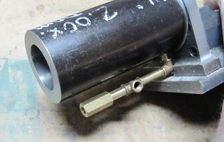
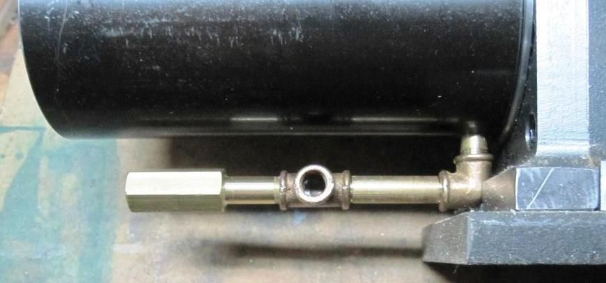
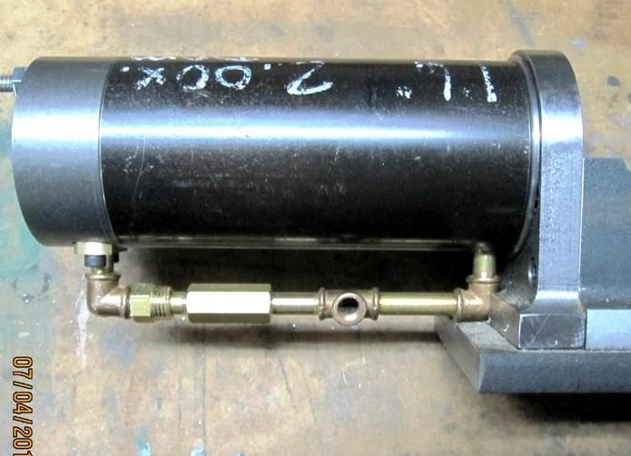
I'm using 1/4" model plumbing parts for starters. The internal diameter of the piping is 5/32", which I hope will be large enough. If not, I may have to revert to 5/16" model plumbing parts which I do have on hand. The hex shaped piece on the left will be a ball check valve which prevents compression from blowing the fuel mixture back down the pipe. Now I have to make a second ball check valve which attaches to the TEE.

Chuck
 
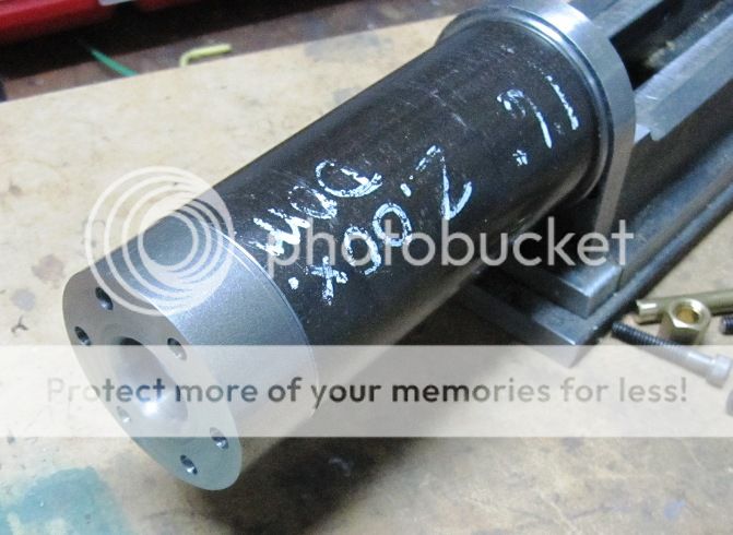
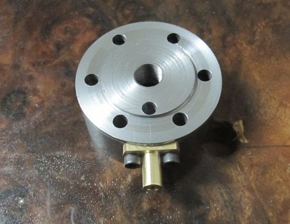
Still a few unknowns between here and the finish line. I got the cylinder head pretty well finished today.

IMG_2834_zpsca08a62f.jpg


IMG_2835_zpsdd2b2811.jpg


IMG_2837_zps7839359d.jpg


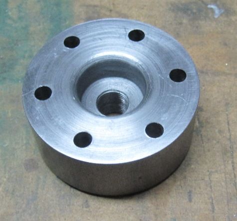
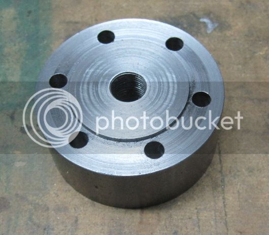
The hole is threaded M10 x 1 to allow the use of a spark plug if my efforts with the hot tube fail. Still have to cut the port which will let the fuel charge into the cylinder but I have a final connector to make before I finalize the head.

Chuck
 
I love those little brass fittings! What's your source for those?
 
Chuck--I'm happy to see you back on this particular build. I am fascinated by this type of engine, and I learn from your posts.---Brian
 
I love those little brass fittings! What's your source for those?

Those come from PM Research.

http://www.pmresearchinc.com/

They sell the castings in little "trees", 3/16", 1/4", and 5/16". They're pretty inexpensive as well. They also sell the nipples, but I just use brass tubing or drilled out rod.

Chuck
 
Chuck--I'm happy to see you back on this particular build. I am fascinated by this type of engine, and I learn from your posts.---Brian

Thanks, Brian, always enjoy knowing you're watching.

Chuck
 
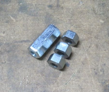
I wanted to use hex nuts and studs to hold the head on but normal hex nuts for 10-24 screws, which are 3/8" across the flats, are not proportioned right for model work. Instead, I bought some all-thread coupling nuts from the local Ace Hardware and was able to get 3 model nuts from each coupling nut.

IMG_2839_zps01b72919.jpg


These coupling nuts are about 3/4" long and 5/16" across the flats. The model nuts, which may still be a bit too thick are .2 inches tall.

Chuck
 
Here's the fixture which will serve as the intake manifold, for lack of a better name...

IMG_2840_zps5cfe59a5.jpg


And here's a shot of the plumbing, at lest the hardest part of the plumbing...

IMG_2841_zps633cc7a5.jpg


Now it remains to be seen how well it seal up. May have to resort to some loctite and soldering to eliminate any leaks.

Chuck
 
Back
Top