Model generator build from scratch

Home Model Engine Machinist Forum

Help Support Home Model Engine Machinist Forum:

This site may earn a commission from merchant affiliate links, including eBay, Amazon, and others.

darwenguy

Well-Known Member
HMEM Supporting Member
Joined
Oct 26, 2013
Messages
216
Reaction score
288
Location
United Kingdom
Hi guys,
Ive been wanting to make a good model dynamo to run with a stationary steam engine.
I dont realy like the kits available from stuarts and pm, i just dont like the price of a modern motor guts in a fancy shell.
I have searched the internet for some plans but had no luck so im going to make my own from scratch.
Il make a full log of the design and build on here as it would be somthing i would want to see myself and i hope it helps somone or someone can help me along the way.
The more i searched the internet the more i become confused aboit generators, so im just starting from the basics i do know and see what works best along the way regarding wiring and magnet arangements.
Il try and keep it as simple as possible and add some cosmetc character to the final model with some nice castings.
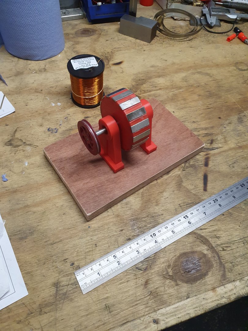
The model will have a stator of 12 fixed windings and i think a rotor with 16 pole magnets.
The first prototype is just being printed in the 3d printer so picks to come soon.
 
Cogging can be an issue with PM generators so I am also curious about the stator-coil ratio you are considering. Can you share the source of that information?
 
Cogging can be an issue with PM generators so I am also curious about the stator-coil ratio you are considering. Can you share the source of that information?
I think it was a link in a feed on here, search generator and someone has made somthing simular. Like i seid its a work in progress and may change along the way.
 
355407, member: 16767"]
I think it was a link in a feed on here, search generator and someone has made somthing simular. Like i seid its a work in progress and may change along the way.
[/QUOTE]
Also this keeps the 3 pbases at 120° (if i go that rout) so only 4 coils are in line with the magnets at one time so reducing drag.
 
Today i made the simple test rig, first test will be with 12coils on the stator and 16 pole magnets on the rotor. With each pole oposing the next ie north, south ,n ,s, ,n ,s.
The stand has small bearings pressed in and a 6mm shaft. The nedimium magnets are 25x8x2mm. The pully was slare from another project.
The enamald coil wire has arrived and its 0.25mm for the first test, il next make a simple former with a counter to wind the coils. Just waiting for a cheep counter in the post.
I do understand that generators work best with a iron rotor core and stator but im aimimg to make this from mostly aluminium alloy castings eventually to reduce drag maybe with just iron core centers.
This will be more like a typical diy style wind generator setup in principle.
 

Attachments

  • 20210227_143802.jpg
    20210227_143802.jpg
    221.8 KB · Views: 401
  • 20210227_143849.jpg
    20210227_143849.jpg
    225.2 KB · Views: 402
It should be understood that cogging isn't a problem, except for motors requiring low starting torque or positional accuracy(servos). Once a motor is turning, cogging is no longer a factor. If building this with no back iron(core), there won't be any cogging anyhow as it's the interaction of the magnet and back iron. If aluminum is used in place of iron, you can expect a lot of "drag" due to magnets inducing eddy currents in the aluminum. The efficiency depends on proper magnetic design, though I understand efficiency is not the goal here. Back iron should be laminated to reduce losses. If coreless is the goal, just print the core? Youtube has several printed motor examples.

You can wind a single coil, test the output, and multiply by the number of coils in series to get an idea of how much voltage it will make. You don't' even have to wind a full coil, just a few turns, but voltage could be too low to measure.

This is approximately the size of a automotive alternator, which can easily make 2kW when wound and driven accordingly.
Im making a generator not motor.
I may use iron cores to increase power dont know yet im making this up as i go along.
 
  • Like
Reactions: kop
http://gpzweb.s3-website-us-east-1.amazonaws.com/RegRec/GPZvRegMagnetField.html
VoltRegMagnetField.gif

Now this is even less than an endorsement however I have heard good things about this company.
Several custom EV designers have reported great conversations with them.
As stated on the site small prototype are available.
https://www.tlclam.net/catalog-of-dies/
The other option is a 3D router w/laser capable of burning through pig iron.

A somewhat caveman kludge is to wind the coils on a bobbin, insert a square headed bolt through the bobbin, drill a hoop with the desired number holes, thread the holes, and insert the bolts/bobbin from the inside.

As you may already know the wiring is connect the starts together and wind one, skip two, wash rinse repeat until you have three free ends that connect to the regulator/rectifier.

TMI? maybe but it's what I have :)
 
http://gpzweb.s3-website-us-east-1.amazonaws.com/RegRec/GPZvRegMagnetField.html
View attachment 123483
Now this is even less than an endorsement however I have heard good things about this company.
Several custom EV designers have reported great conversations with them.
As stated on the site small prototype are available.
https://www.tlclam.net/catalog-of-dies/
The other option is a 3D router w/laser capable of burning through pig iron.

A somewhat caveman kludge is to wind the coils on a bobbin, insert a square headed bolt through the bobbin, drill a hoop with the desired number holes, thread the holes, and insert the bolts/bobbin from the inside.

As you may already know the wiring is connect the starts together and wind one, skip two, wash rinse repeat until you have three free ends that connect to the regulator/rectifier.

TMI? maybe but it's what I have :)
Hi. I think the wiring diagram is over kill for my needs. I have a variety of bridge rectifier diodes to try and il probably just use a capacitor to stabalise the voltage a little. And simply regulate it with the speed, i only want to produce around 6v to run maybe a few lights for display.
I have capability to cast the parts in iron if i need too, i just prefer to use alloy casting.
Il wind the coils on a bobbin then make a former to shape them to the stator frame.
Im not sure yet how i will wire it, il first do some tests to see what works best.
 
Generator and motor are the same, only the direction of energy transfer differs. I'll refrain from further comment unless asked.
 
With 12 coils and 16 magnetic poles, what frequency would result by spinning it at 1000 RPM?
 
Next to copper, aluminum is about the worst stuff that you can use for efficiency. Just consider that magnetic brakes are, essentially, magnets held up to a good conductor that's moving. Back irons behind the magnets and the coils will significantly increase efficiency, and far more so if you use laminations that are electrically isolated from one another (the traditional thing to do is use varnish -- just about any paint-like material will work).

Personally, if I could find a sheet of magnet iron and I had a laser printer (or a friend with one) I'd cut out a stack of laminations from that, varnish them, and stack them.

Alternately, I've always wanted to try getting hunks of ferrite, and having them laser- or water-cut to shape.

If you don't want to mess with back iron, consider making the whole thing out of bakelite, or some other non-conductive material.
 
Back
Top