
You are using an out of date browser. It may not display this or other websites correctly.
You should upgrade or use an alternative browser.
You should upgrade or use an alternative browser.
Model engine CDI easy and cheap
- Thread starter bluejets
- Start date


Help Support Home Model Engine Machinist Forum:
This site may earn a commission from merchant affiliate
links, including eBay, Amazon, and others.
A great suggestion, I found this on the web:
Starting in 1997, General Motors used a new (for them) coil-near-plug ignition system for the then new Corvette LS1 engine. The system features eight coils (one per cylinder) mounted on the valve cover, with short spark plug wires to connect the coils to the spark plugs. The General Motors LS1 coils are not just conventional ignition coils. Instead they are complete single-cylinder ignition systems. They contain all the electronics for dwell limiting, current limiting, etc. These coils are controlled directly by a low voltage, low current signal from the sequencer. There is no intervening ignition module (like an EDIS or GM DIS). Because the LS1 coils have the igniters built in, they make for an easy installation and generate less electromagnetic noise in the other wiring under the hood.
The LS1 coil has 4 connections (as well as the high tension terminal for the spark plug wire, of course):
Sounds easy, but a bit more expensive.
Starting in 1997, General Motors used a new (for them) coil-near-plug ignition system for the then new Corvette LS1 engine. The system features eight coils (one per cylinder) mounted on the valve cover, with short spark plug wires to connect the coils to the spark plugs. The General Motors LS1 coils are not just conventional ignition coils. Instead they are complete single-cylinder ignition systems. They contain all the electronics for dwell limiting, current limiting, etc. These coils are controlled directly by a low voltage, low current signal from the sequencer. There is no intervening ignition module (like an EDIS or GM DIS). Because the LS1 coils have the igniters built in, they make for an easy installation and generate less electromagnetic noise in the other wiring under the hood.
The LS1 coil has 4 connections (as well as the high tension terminal for the spark plug wire, of course):
- A = Coil Primary Ground (to engine block)
- B = Signal Ground (to engine block)
- C = +5V Ignition signal
- D = Switched +12V Supply to Coil Primary
Sounds easy, but a bit more expensive.
Can the CDI drive two coils simultaneously? I am looking for an ignition system for a inline twin cylinder engine with a single hall sensor pickup and wasted spark. The pistons move in unison, one is on the power stroke while the other is on the exhaust stroke. An ignition system that has a magnet on the crankshaft and a hall sensor that fires a CDI unit once a crankshaft revolution that could drive two coils would produce a spark to the two cylinders simultaneously. One would fire the power stroke and the other would be wasted.
I really like the idea of using the inexpensive 12DV CDI units for skooters and mopeds. But could one fire two coils instead of one? Without knowing the inside circuitry of the CDI unit, the switching transistor driving the coils in parallel would see half the resistance and be required to drive twice the current. Don't know if it could handle that.
there are six cylinder car engines that use this technique, firing two of the six cylinders simultaneously, one with wasted spark. I have not been able to find one of the CDI units as inexpensive as the moped variety.
Any other suggestions? Using a wasted spark ignition would eliminate the distributor.
Thanks
No, cdi systems don't work like kettering systems.
This one was designed to drive one coil.
Use two "black boxes" and circuitry for each and you'll be fine.
It’s a good solution, All car petrol engines use these now, you can get them for pennies second hand. Also for the signal you can use 12v no issues as it’s just a logic signal, which makes the wiring even easier. I use mine with points on one engine and a magnetic Reed switch on another. Very simple and very cheapA great suggestion, I found this on the web:
Starting in 1997, General Motors used a new (for them) coil-near-plug ignition system for the then new Corvette LS1 engine. The system features eight coils (one per cylinder) mounted on the valve cover, with short spark plug wires to connect the coils to the spark plugs. The General Motors LS1 coils are not just conventional ignition coils. Instead they are complete single-cylinder ignition systems. They contain all the electronics for dwell limiting, current limiting, etc. These coils are controlled directly by a low voltage, low current signal from the sequencer. There is no intervening ignition module (like an EDIS or GM DIS). Because the LS1 coils have the igniters built in, they make for an easy installation and generate less electromagnetic noise in the other wiring under the hood.
The LS1 coil has 4 connections (as well as the high tension terminal for the spark plug wire, of course):
- A = Coil Primary Ground (to engine block)
- B = Signal Ground (to engine block)
- C = +5V Ignition signal
- D = Switched +12V Supply to Coil Primary
Sounds easy, but a bit more expensive.
I am pulling the bits and bobs together for my prototype:

You can see in the lower left the DC motor with a magnet mounted on the shaft, with the hall sensor underneath. I have my prototype board ready for the circuit. I'll keep you all posted on my progress.
You can see in the lower left the DC motor with a magnet mounted on the shaft, with the hall sensor underneath. I have my prototype board ready for the circuit. I'll keep you all posted on my progress.
- Joined
- May 15, 2017
- Messages
- 481
- Reaction score
- 298
Could you use contact breaker or a microswitch, set to be normally open, for this type of coil?
I am pulling the bits and bobs together for my prototype:
View attachment 133933
You can see in the lower left the DC motor with a magnet mounted on the shaft, with the hall sensor underneath. I have my prototype board ready for the circuit. I'll keep you all posted on my progress.
Just be aware that using those crappy breadboards can, in many instances, give you bad connections and you can chase problems all over not realising it.
Vixen
Well-Known Member
Paulc you have been sent a PM
Mike
Mike
A little progress:

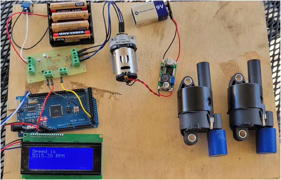
I am working on my electronic ignition for my twin cylinder 4 stroke. Here I am using a DC motor with a magnet mounted on a collar triggering a hall sensor--this simulates the setup on the engine. I will use a magnet mounted to the crank and fire both spark plugs at the same time, ie wasted spark. I will use a little microcontroller to adjust the timing advance from 5 to 25 degrees before top dead center depending on the RPM. The circuit board has the analog circuitry that converts the hall sensor output to a nice 1 millisecond pulse, and then another transistor stage that will drive the coil over plug (COP)s from a signal generated by the microcontroller. The pulse to the COPs will be 4 millisecond in duration. This will diminish if the RPMs get high enough to not exceed a 50% duty cycle on the COP trigger signal.
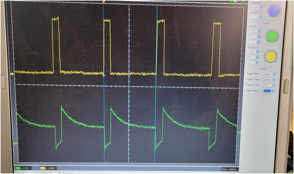
Below is a scope trace of a couple of key signals in the analog circuitry. the green is the signal generated by the RC circuit triggered by the hall sensor, and the yellow is the pulse on the output of the NPN transistor, the RC time constant is set for a 1 millisecond pulse.
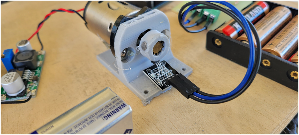
Below is the DC motor setup to simulate the hall sensor on the engine. I can control the motor speed by adjusting the voltage is sees.
Next up is wiring the COPs and the sparkplugs. We will see what EMI havoc is caused by the high voltage travelling through the sparkplug wires.
I am working on my electronic ignition for my twin cylinder 4 stroke. Here I am using a DC motor with a magnet mounted on a collar triggering a hall sensor--this simulates the setup on the engine. I will use a magnet mounted to the crank and fire both spark plugs at the same time, ie wasted spark. I will use a little microcontroller to adjust the timing advance from 5 to 25 degrees before top dead center depending on the RPM. The circuit board has the analog circuitry that converts the hall sensor output to a nice 1 millisecond pulse, and then another transistor stage that will drive the coil over plug (COP)s from a signal generated by the microcontroller. The pulse to the COPs will be 4 millisecond in duration. This will diminish if the RPMs get high enough to not exceed a 50% duty cycle on the COP trigger signal.
Below is a scope trace of a couple of key signals in the analog circuitry. the green is the signal generated by the RC circuit triggered by the hall sensor, and the yellow is the pulse on the output of the NPN transistor, the RC time constant is set for a 1 millisecond pulse.
Below is the DC motor setup to simulate the hall sensor on the engine. I can control the motor speed by adjusting the voltage is sees.
Next up is wiring the COPs and the sparkplugs. We will see what EMI havoc is caused by the high voltage travelling through the sparkplug wires.
Can someone confirm that modern coil over plug ignition systems as seen on bikes and cars today are using a transistorized ketering or CDI triggers?
I'd imagine those tiny coils above each plug would be CDI?
I'd imagine those tiny coils above each plug would be CDI?
I can only speak to the COP I am using, the LS2 coil (GM# 12573190). these are common in the US, I bought mine on Amazon.
The connector can be bought here: Mouser 829-15439568. I made my connectors by printing them on my 3D printer.
The LS2 coil has 4 connections (as well as the high tension terminal for the spark plug wire, of course):
A = Coil Primary Ground
B = Ignition low noise ground from ECU (ground)
C = Ignition digital signal from ECU (+5V)
D = +12V Supply to Coil Primary

The maximum dwell should be set at 4.5 milliseconds - going longer does not generate any more spark energy.
The connector can be bought here: Mouser 829-15439568. I made my connectors by printing them on my 3D printer.
The LS2 coil has 4 connections (as well as the high tension terminal for the spark plug wire, of course):
A = Coil Primary Ground
B = Ignition low noise ground from ECU (ground)
C = Ignition digital signal from ECU (+5V)
D = +12V Supply to Coil Primary
The maximum dwell should be set at 4.5 milliseconds - going longer does not generate any more spark energy.
You might find there is alread a/r built in to the black box if using the originalA little progress:
I am working on my electronic ignition for my twin cylinder 4 stroke. Here I am using a DC motor with a magnet mounted on a collar triggering a hall sensor--this simulates the setup on the engine. I will use a magnet mounted to the crank and fire both spark plugs at the same time, ie wasted spark. I will use a little microcontroller to adjust the timing advance from 5 to 25 degrees before top dead center depending on the RPM. The circuit board has the analog circuitry that converts the hall sensor output to a nice 1 millisecond pulse, and then another transistor stage that will drive the coil over plug (COP)s from a signal generated by the microcontroller. The pulse to the COPs will be 4 millisecond in duration. This will diminish if the RPMs get high enough to not exceed a 50% duty cycle on the COP trigger signal.
Below is a scope trace of a couple of key signals in the analog circuitry. the green is the signal generated by the RC circuit triggered by the hall sensor, and the yellow is the pulse on the output of the NPN transistor, the RC time constant is set for a 1 millisecond pulse.
Below is the DC motor setup to simulate the hall sensor on the engine. I can control the motor speed by adjusting the voltage is sees.
Next up is wiring the COPs and the sparkplugs. We will see what EMI havoc is caused by the high voltage travelling through the sparkplug wires.
Eccentric, this is most interesting. Is the "igniter" circuit shown above built into those COP units, or are you needing to build that part?
The ignitor is built into the COP, that is why they are so nice. All you need to do is provide a simple 5 Volt, low current pulse to trigger it.
That is very cool. I will definitely check that out!
willray
Well-Known Member
The ignitor is built into the COP, that is why they are so nice. All you need to do is provide a simple 5 Volt, low current pulse to trigger it.
Could you please provide more information on how you're handling dwell?
I see there is someone successfully running small-equipment type engines (kohler, tecumseh, onan, small-HP engines) using a GM inductive crank trigger to provide the pulse for these, but I'm having trouble figuring out how that works.
Some reading says that these coils like 3-5 ms dwell, and back-of-the-napkin calculations say that a crank trigger at 3600RPM probably provides an on-time of something like (360 degrees * 60 revolutions per second = 21600 degrees per second, 1 degree subtended/21600 degrees/second = 0.05 milliseconds). 0.05ms doesn't sound like it's even remotely enough dwell, so how that even works mystifies me, but it sounds like you're doing something more sophisticated. I'd love to learn more.
@willray
The coil I am using likes to see as you say, about 4ms of dwell. This is the time to charge the coil and determines the energy of the spark. If my engine is running at 4000 RPM and I am using wasted spark where I fire both spark plugs every revolution of the crankshaft, I need to fire the spark plugs every 15 milliseconds. (4000 RPM is 66.7 Revolutions per second, or 1/66.7 = .015) Of this 15 milliseconds, 4ms is used to charge the coil. At 7500RPM, the crankshaft is turning 125 times a second, or once every 8 milliseconds. We still have half of this time to charge the coil.
When the engine is running, the crankshaft rotates and the magnetic sensor produces a reference pulse each revolution. These are fed to the microcontroller, which records the time of each reference to microsecond accuracy on an internal clock. From these times the RPM is calculated and the required timing advance angle is derived. The actual time of the next spark is calculated, and when the clock reaches this value, the pair of plugs fire. For starting, the priority is to prevent kickback and ensure a big spark. To achieve this the spark occurs at 3 degrees AFTER TDC. The active edge of the magnet is physically installed at this point and this generates the spark immediately. Both spark plugs are fired in my twin engine, thus one spark is “wasted” as it occurs at the end of the exhaust stroke, and so has no effect. The benefit of this is that no distributor is required and the accuracy of the spark timing is improved, as the timing is taken directly from the crank, not through the gear driven camshaft. The microcontroller does a number of other things as well as controlling the main timing process.
The spark timing is as follows: from 0 to 500 RPM the spark is fired 3 degrees after TDC. From 500 RPM to 1000 RPM the spark is advanced to 7 degrees before TDC. From 1000 RPM to 3000 RPM the timing is advanced linearly from 7 to 25 degrees before TDC. From 3000 RPM to 5000 RPM the timing is advanced to 25 degrees before TDC. Above 5000 RPM the spark is not advanced and set to TDC. This is an over rev limiter of sorts.
The microcontroller uses at minimum a 25 microsecond time base, which equates to one degree timing resolution up to 6667 RPM.
Does this answer your question?
If anyone is needing more info on the LS1/2 coils here are some links that explain more about dwell timing requirements including using coil charge voltages from 6v to 16v. The testing I have done so far is with 5v and 12v signals and can say that both voltages work fine. From what I have read a minimum signal is between 3-5v depending if you are using the LS1 or LS2 coil. The LS2 coil is mainly used on the truck engines and is the preferred one to use. There is a max to the trigger signal duration (dwell), if you go above this value the coils will self discharge (6-8 msec). From my testing I found the same as others above 2 msec duration you get into diminishing returns and just create heat.
Excellent info from Haltech a leader in engine management systems:
Haltech Support Center
Very good write up with lots of testing:
LSx Coil Testing
Cheers
Ray
Excellent info from Haltech a leader in engine management systems:
Haltech Support Center
Very good write up with lots of testing:
LSx Coil Testing
Cheers
Ray
willray
Well-Known Member
@willray
....
When the engine is running, the crankshaft rotates and the magnetic sensor produces a reference pulse each revolution. These are fed to the microcontroller, which records the time of each reference to microsecond accuracy on an internal clock. From these times the RPM is calculated and the required timing advance angle is derived. The actual time of the next spark is calculated, and when the clock reaches this value, the pair of plugs fire. For starting, the priority is to prevent kickback and ensure a big spark. To achieve this the spark occurs at 3 degrees AFTER TDC...
...
Does this answer your question?
Perfectly - thanks!
It looks like this would be easy to implement as an interrupt-driven process that simply wakes up uC every time it sees the reference pulse and calculates the delay until it needs to turn the coil back on for the next planned plug firing.
For some reason I was imagining the calculation of the anticipated delay to be harder than this - I'm not sure why my brain wanted to use a sliding average over several revolutions...
One question: It seems like the straightforward way to implement this strategy would result in missing (firing extremely late) on the first revolution after the very first successful "pop" when starting the engine: After the first cylinder fires for the first time when cranking, the next revolution will be much faster than anticipated from the previous one. At least in theory, this could result in the uC not getting around to turning on power to the coil, until after TDC comes around and it should have fired.
At least conceptually, this seems like it would limit your acceleration - below 500RPM, if the next revolution is faster than 4ms faster than the previous revolution, the coil turn-on would happen after it should fire?
I take it that in practice, this isn't a problem?
Similar threads
- Replies
- 0
- Views
- 164
- Replies
- 245
- Views
- 31K
- Replies
- 2
- Views
- 944
- Replies
- 61
- Views
- 8K