


B
Bogstandard
Guest
Before I start on this post, I will mention that this was done to a brand new spindex, and the unit as purchased was perfectly good for what it is intended to do. I did the modifications purely to make it easier for me to set up on the mill and to allow it to be used in my vice.
Basically, what I am going to do is make the base of the unit smaller to allow if to fit in my vice jaws, and to fit a bar onto the bottom to allow it to be dropped into one of the t-slots on the mill bed, clamp down and be ready for use without having to level it all up first.
This is what one looks like when it falls apart, with a bit of help from me.
The only difference with this one, is that it has been modified for the retailer to accept both 5c and ER32 collets.

Because I want to fit this without having to check for levels, I needed a datum to work with. The only component that fits the bill is the unit's spindle. Get this level with the table and square to the already checked for squareness t-slots, and work from that.
In a previous post from my workshop rebuild, I made some brass bar that was a nice push fit into the t-slots. I cut it into two, and put them into the table slots, as shown. Then pushed a matched pair of v-blocks against the slot blocks, and popped the spindle into the v's.
While the spindle was in this position, I carefully checked for runout along the top.

Then against the side face. Everything was spot on.
I now had the datum I could work to. So the main casting was assembled onto the spindle upside down and everything was clamped up, making sure the spindle was down into the v's and the v's were against the slot blocks. The spindle was then clamped down. The main casting was then jacked and clamped in position, plus they were adjusted so that when a circular tram was done on the base, everything was in the right position and level.

The base was skimmed with a 3 thou cut using a fly cutter, just to give me a guaranteed square and level face in relation to the spindle.

If you squint and look at the area in the middle on the circle, it shows the fly cutting machining pattern. If you can see both fwds and back cutting patterns overlapping, that is a sure sign your tramming for the head is spot on.
Lesson over, get on with the job. I had a piece of BMS bar that fitted perfectly into the slots on the table. A slot was cut into the base, exactly the same width as the bar (and slots).

The bar was fitted into the groove, to check there was no side play.

Bar was clamped, drilled and counterbored. The base casting was drilled and tapped to match the holes on the location bar.
Everything was cleaned up and the bar screwed into its final position.

I machined the bar to a thickness of about 1/4" protruding above the baseplate, and rounded over the edges. This ensured it will fit nicely into the table slots, without getting itself jammed on the bits of rough stuff or machining marks in the slots.
That was the location bit sorted, now for getting it so that it fits in my vice. Front to back was no problem as that was under the 4" (plus a bit) my vice jaws open, side to side was the problem, so I decided to remove 1/2" from each side face to get me within easy fitting limits.

The location bar needed to be cleaned up on the ends anyhow, so I took a skim off both casting end faces at the same time. Because I had set up the datum on the spindle, all cuts on the base will be perfectly square to the said spindle, so why not get everything done at the same time.

The side faces then had the 1/2" removed from either side.
Now is the time to find out if my setup and machining is out of wack.
A good clean down and basic assembly of the unit. This was then clamped to the table (no hand detectable side play in the slots). A collet and bar was fitted and the whole lot trammed up.

Half a thou runout along the top face, from the collet to about 4" out.

Along the side face, for the same checking distance, just over 1.5 thou. I expected this because of the minor imperfections in the table slots. I am very happy to work with those sorts of tolerances, in the knowledge I could most probably only have got that close using a manual setup anyway. To have it as a drop in and clamp, no further checking, grins all round.

Now for a few mods that I thought necessary.
Firstly, the main disc isn't locked onto the main spindle, so a bit of rough machining could cause it to move out of register as the spindle rotated inside the disc. I did a quick check, hoping to put a small locking pin between the two, the disc was soft enough, but the spindle was too hard to drill. So I assembled the disc, spindle and locking collar using Loctite engineering adhesive. That, hopefully, should prevent anything untowards happening.
The next little mod was to drill a lubrication hole and cup into the casting. Just to put a drop of thin oil in, and keep everything turning smoothly.
I am a bit of a stickler in that things should be right. The little Chinese chap that had stamped the indicator mark to show angle position, was either cross eyed or he had a bit too much rice wine the night before, because it was showing a couple of degrees out. I just machined out the old mark and popped one of my own on there in the correct position.

Back end.

Front end.

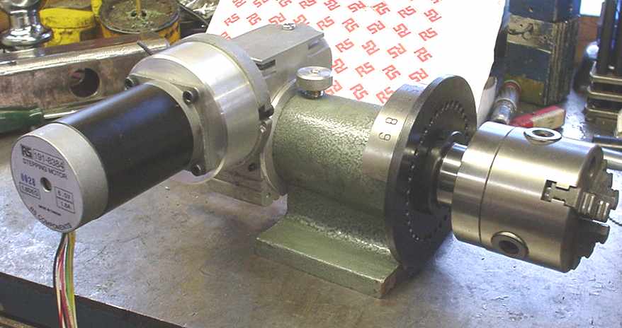
Job done, pleased with the results, and it showed that my machine was accurate enough.
Happy bunny John
Basically, what I am going to do is make the base of the unit smaller to allow if to fit in my vice jaws, and to fit a bar onto the bottom to allow it to be dropped into one of the t-slots on the mill bed, clamp down and be ready for use without having to level it all up first.
This is what one looks like when it falls apart, with a bit of help from me.
The only difference with this one, is that it has been modified for the retailer to accept both 5c and ER32 collets.
Because I want to fit this without having to check for levels, I needed a datum to work with. The only component that fits the bill is the unit's spindle. Get this level with the table and square to the already checked for squareness t-slots, and work from that.
In a previous post from my workshop rebuild, I made some brass bar that was a nice push fit into the t-slots. I cut it into two, and put them into the table slots, as shown. Then pushed a matched pair of v-blocks against the slot blocks, and popped the spindle into the v's.
While the spindle was in this position, I carefully checked for runout along the top.
Then against the side face. Everything was spot on.
I now had the datum I could work to. So the main casting was assembled onto the spindle upside down and everything was clamped up, making sure the spindle was down into the v's and the v's were against the slot blocks. The spindle was then clamped down. The main casting was then jacked and clamped in position, plus they were adjusted so that when a circular tram was done on the base, everything was in the right position and level.
The base was skimmed with a 3 thou cut using a fly cutter, just to give me a guaranteed square and level face in relation to the spindle.
If you squint and look at the area in the middle on the circle, it shows the fly cutting machining pattern. If you can see both fwds and back cutting patterns overlapping, that is a sure sign your tramming for the head is spot on.
Lesson over, get on with the job. I had a piece of BMS bar that fitted perfectly into the slots on the table. A slot was cut into the base, exactly the same width as the bar (and slots).
The bar was fitted into the groove, to check there was no side play.
Bar was clamped, drilled and counterbored. The base casting was drilled and tapped to match the holes on the location bar.
Everything was cleaned up and the bar screwed into its final position.
I machined the bar to a thickness of about 1/4" protruding above the baseplate, and rounded over the edges. This ensured it will fit nicely into the table slots, without getting itself jammed on the bits of rough stuff or machining marks in the slots.
That was the location bit sorted, now for getting it so that it fits in my vice. Front to back was no problem as that was under the 4" (plus a bit) my vice jaws open, side to side was the problem, so I decided to remove 1/2" from each side face to get me within easy fitting limits.
The location bar needed to be cleaned up on the ends anyhow, so I took a skim off both casting end faces at the same time. Because I had set up the datum on the spindle, all cuts on the base will be perfectly square to the said spindle, so why not get everything done at the same time.
The side faces then had the 1/2" removed from either side.
Now is the time to find out if my setup and machining is out of wack.
A good clean down and basic assembly of the unit. This was then clamped to the table (no hand detectable side play in the slots). A collet and bar was fitted and the whole lot trammed up.
Half a thou runout along the top face, from the collet to about 4" out.
Along the side face, for the same checking distance, just over 1.5 thou. I expected this because of the minor imperfections in the table slots. I am very happy to work with those sorts of tolerances, in the knowledge I could most probably only have got that close using a manual setup anyway. To have it as a drop in and clamp, no further checking, grins all round.
Now for a few mods that I thought necessary.
Firstly, the main disc isn't locked onto the main spindle, so a bit of rough machining could cause it to move out of register as the spindle rotated inside the disc. I did a quick check, hoping to put a small locking pin between the two, the disc was soft enough, but the spindle was too hard to drill. So I assembled the disc, spindle and locking collar using Loctite engineering adhesive. That, hopefully, should prevent anything untowards happening.
The next little mod was to drill a lubrication hole and cup into the casting. Just to put a drop of thin oil in, and keep everything turning smoothly.
I am a bit of a stickler in that things should be right. The little Chinese chap that had stamped the indicator mark to show angle position, was either cross eyed or he had a bit too much rice wine the night before, because it was showing a couple of degrees out. I just machined out the old mark and popped one of my own on there in the correct position.
Back end.
Front end.
Job done, pleased with the results, and it showed that my machine was accurate enough.
Happy bunny John
")