ML Midge aero engine

Home Model Engine Machinist Forum

Help Support Home Model Engine Machinist Forum:

This site may earn a commission from merchant affiliate links, including eBay, Amazon, and others.
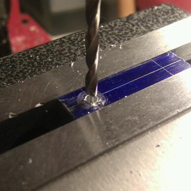
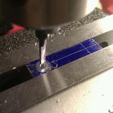
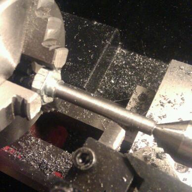
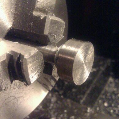
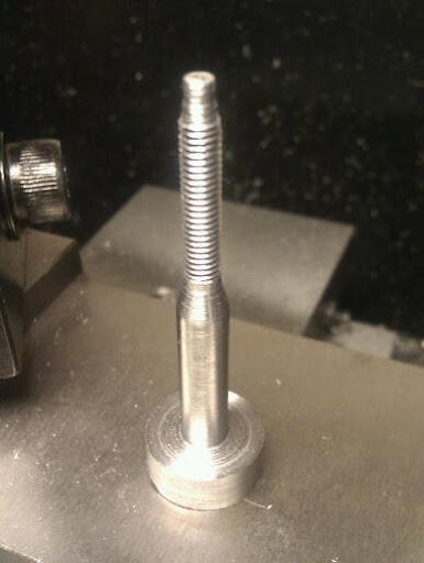
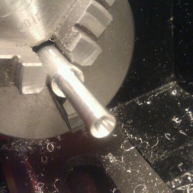
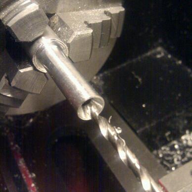
Tonight I thought I'd make the D bit reamers needed for the conrod. I started by turning down some silver steel to accurate diameter, and gave a light chamfer on the end to ease entry to the hole. I made one of these blanks for each of the two diameters required (3mm and 2.5mm):
IMG_20110815_231949-1.jpg


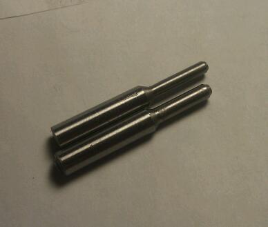
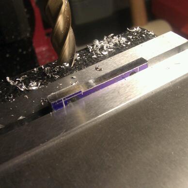
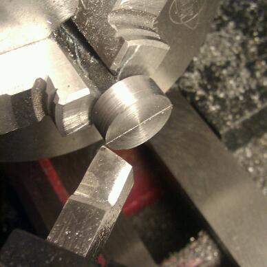
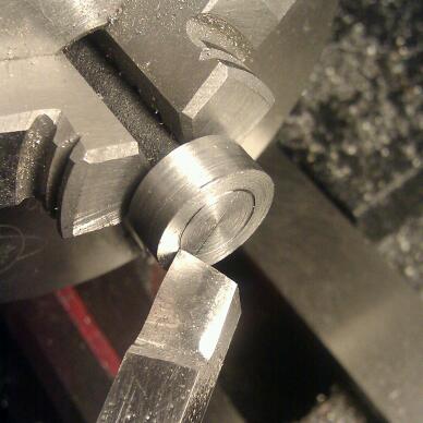
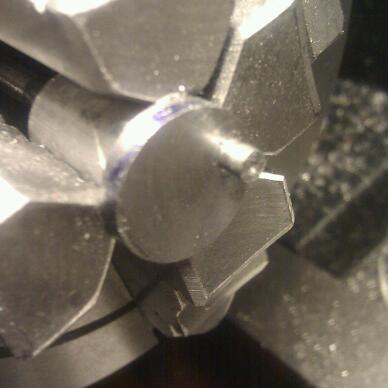
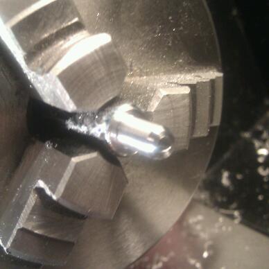
Next I filed those to half thickness:
IMG_20110815_234744-1.jpg


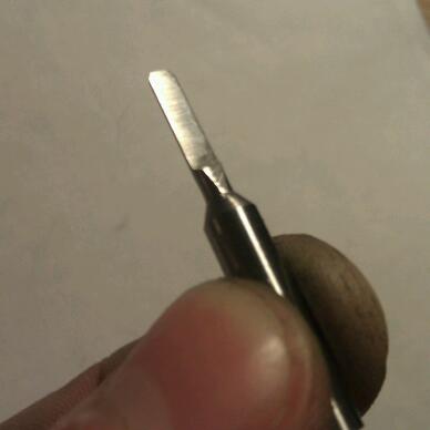
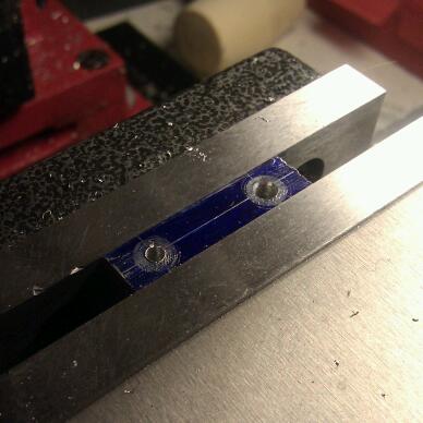
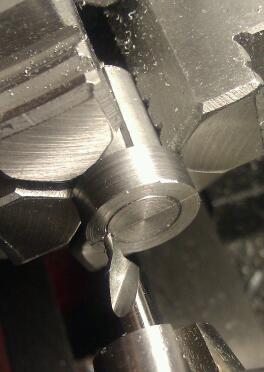
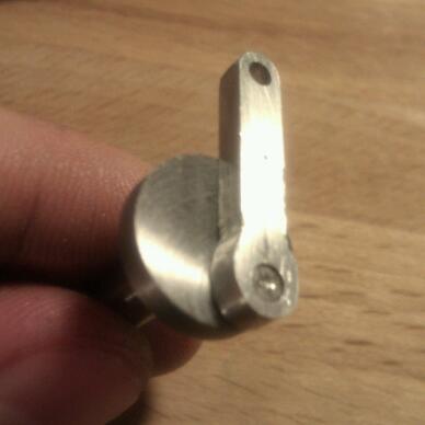
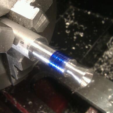
Next up I heat treated them with a small pencil torch. I didn't take any photos of these steps - I was kind of busy ;) - but it was an easy process. First I heated them to cherry red, quenched in water, then polished the flat face and tempered to a dark straw by heating the base and watching the colours creep towards the tip. It goes VERY fast with tools this small. Result (apologies for the lack of focus, I couldn't get my camera to reliably focus):
IMG_20110816_000819-1.jpg


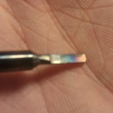
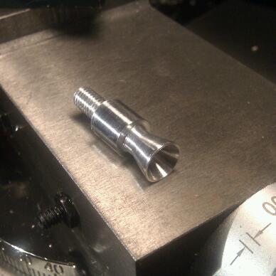
I honed the flat face to finish the tools.
This was an easy and enjoyable process :)
 
Tonight I thought I'd tackle the connecting rod. I prepared a blank of aluminium, marked out for the holes, centre drilled and drilled them undersize:
IMG_20110816_222653-1.jpg


Then I ran them through with the reamers I made last night:
IMG_20110816_222852-1.jpg


As per the plans, I lightly countersunk the big end bearing:
IMG_20110816_223819-1.jpg


Next I marked out a vaguely conrod-shaped thing on the blank and milled away everything that didn't look like a conrod:
IMG_20110816_225322-1.jpg


And finally filed it closer to final shape. The final shaping takes part at the end when attempting to assemble for the first time.
IMG_20110816_231715-1.jpg
 
I finished the conrod faster than expected last night, so I started on the crankshaft.
It starts out as one M10 50mm high tensile steel bolt (look for the 8.8 on the head), ~17mm across flats:
IMG_20110816_233744-1.jpg


It is set to run fairly true in the 3-jaw chuck and delicately centre drilled so it can be supported with a centre. The threads were then turned off:
IMG_20110817_001546-1.jpg


After which it was reversed in the chuck and the head turned down to ~15mm and faced:
IMG_20110817_003300-1.jpg


I didn't take any in progress shots for the next few turning steps, but I flipped it back around in the chuck, turned the front of the shaft down to just over 4mm and the rest to just over 6mm. I then machined the 15 degree angle transition, which was rather tricky as the electronics box for the lathe gets in the way of the top slide. I had to juggle everything around a fair bit to find a setting that would let me machine the whole taper. Next I faced the underside of the head of the bolt (err, I mean, the crankweb ;) ) and added the little step called for in the plans. After that I very slowly eased the 6mm part down until it would be a press fitting into the bearing, then I polished it with emery cloth so it would rotate fairly smoothly.
Then came the reason for the delay since my last post - threading the shaft M4. I chamfered the end of the shaft by 45 degrees but I just wasn't able to get the die started. Figuring it was due to the cheap tap & die set I have (I'm replacing them piece by piece with higher quality items as they break) I ordered a higher quality die and waited for that to arrive. No joy. Scratching my head, I checked the shaft diameter - I had left it at 4.1mm! Silly me... I chucked it again and took it down to about 3.96mm or so and a small shoulder to help starting and then went ahead and cut the thread. No problems this time.

That brings us up to date with my efforts this evening:
IMG_20110824_231637-1.jpg


As I have a 4-jaw chuck and I'm only building one of these (so far) I chose not to make the offset collet to turn the crank pin. Instead I marked out the location for the crank pin centre by first very carefully setting my lathe tool to centre height, and using the cross slide to mark it straight across the centre:
IMG_20110824_231038-1.jpg


Then I set it to be as close to dead centre as I could manage, calculated how many ticks to wind the cross slide back to achieve a 5mm offset, and wound it on back. I rotated the chuck by hand to score the 5mm radius:
IMG_20110824_231511-1.jpg


I made up a little aluminium collet to hold the shaft for the offset turning operation as the chuck couldn't grip such a small radius at such a large offset. I spent some time making sure the marked location was well centred, then I spotted a little centre there just in case I needed to re-set it later:
IMG_20110825_000214-1.jpg


I took my time with the offset turning and as a result the piece did not slip and I did not need to use the centre. I took off tiny amounts with each pass at the end, taking off about 0.0005" at a time until the conrod fit nicely. Here's the resultant crank pin:
IMG_20110825_004930-1.jpg


And the fit - the conrod is slightly thicker than 3mm for now, hence it is slightly proud of the crank pin:
IMG_20110825_005718-1.jpg


Just to see how successful my homemade reamer had been, I measured the crank pin - bang on 2.99mm. It seems like the reamer did a fine job!

Here is where I'm at overall:
IMG_20110825_005941-1.jpg


I'm not sure which part to tackle next - I'm feeling a bit nervous about machining the cast iron for the piston!
 
After procrastinating all week I decided to get back into it by making one of the simple parts - the carburettor body. This was pretty straightforward - I turned down a length of aluminium bar to 8mm and centre drilled with my biggest drill to create the venturi:
IMG_20110904_202358-1.jpg


Then I drilled through with a 3.2mm drill:
IMG_20110904_202816-1.jpg


I set the top slide over to roughly 15 degrees to profile the outside of the venturi:
IMG_20110904_205113-1.jpg


Next I parted off and reversed the part in the chuck with some emery cloth protecting the finish. I turned it down to 5mm and chamfered the edge:
IMG_20110904_210557-1.jpg


Finally I threaded the 5mm part. All that remains to do is to cross-drill and tap M4:
IMG_20110904_230457-1.jpg
 
hi Trizza!
nice build! very inspirational! noticed you started several years ago! did you finish it?
Kind Regards Rodrigo
 
Back
Top