mini-lathe - getting it right...maybe

Home Model Engine Machinist Forum

Help Support Home Model Engine Machinist Forum:

This site may earn a commission from merchant affiliate links, including eBay, Amazon, and others.

zeeprogrammer

Well-Known Member
Joined
Mar 14, 2009
Messages
3,362
Reaction score
13
For all the poor souls that have followed my locomotive thread...I present a project that I hope will allow me to complete said thread.

Time to fix/modify/adjust/tweak/but probably just learn how to properly use...my mini-lathe.

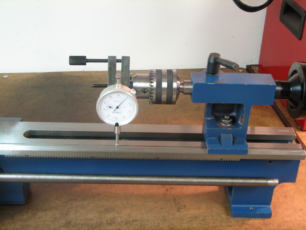
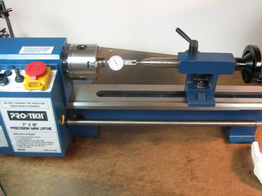
The issue I'm hunting is true-ness (okay...and skill). Tailstock, chuck-run-out, anything that is a hindrance (other than my personal skill) in making 'good' parts.

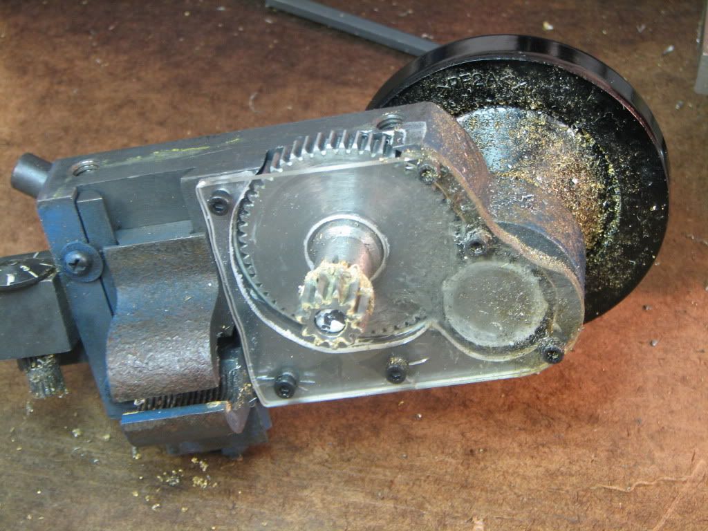
First step is to break it down and clean it up.

Aha! Immediately we see that zeepster doesn't know the difference between 'tight enough' and 'enough to throttle the life out of it'.

43995e2b.jpg


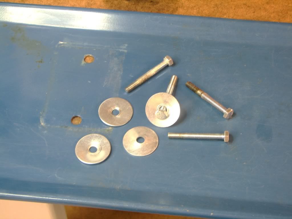
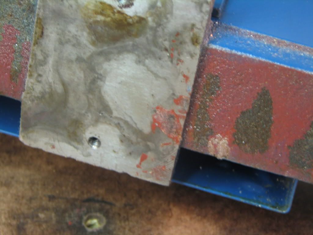
Here we see the pan. Evidence includes bent washers and dents where the feet of the lathe sat.

Could this cause twist in the lathe bed? Could this cause bend in the lathe bed?

Why of course it could.

We now have two audiences...audience one is thinking to themselves, 'dolt' and audience two is thinking 'hm...maybe I have the same problem'. (I discount the audience saying 'huh?'. I used to be in the audience.)

I encourage audience one to help me as I go along. Their experience and knowledge is invaluable. I encourage audience two to follow along. My hope is that they will learn from audience one...cause they ain't going to get it from me.

But alas..this will take some time. I have much to do that will take me away...but I hope to make progress when I can.

Thank you. Thank you very much.

........................................

This post comes with no guarantee or warranty. Said thread may stop suddenly and without warning (as one or two of my previous threads have done). Be prepared for nonsense, stupid questions, dumb attempts, but a good heart. Reply at your own risk.

And before anyone says it...yes...I'm feeling good. Got visitors and we share a similar interest. ;D
 
zeeprogrammer said:
And before anyone says it...yes...I'm feeling good. Got visitors and we share a similar interest. ;D


Vodka?
 
zeeprogrammer said:
The issue I'm hunting is true-ness (okay...and skill).

Carl,

I have always found you to be true. :bow: Hunt 1 over. ::)

Better take a cut lunch and a 0.38" hunt 2 could take a little longer. :mad:

Seriously, Yep, you overdid it but then again your a pretty big man from what I can gather so don't sweat it.

Without buying an Engineers Level I thoroughly recommend "Roleys Dad's" method easy to find and download from the net.

Before you do that put you centres in the head and tail stock and bring them to almost touching and see what's what with the lathe unbolted.

Let's know how you get on.

Best Regards
Bob
 
Ahh yes , Bob speaks wisdom here

I know Rollie....he knows what he's talking about....

Can't help you with the common interest...though I think I might want to ;D.....shaken or stirred?

Dave
 
Yep Dean. Your prize is in the shout box. ;D

Thanks Bob. I remember seeing the "Roley's Dad" method elsewhere in the forum.

Using dead centers in the headstock and tailstock is what told me that things were off. That's the first thing I'll look at when I get the lathe back together. But that's just a start. That is, it tells me if things are aligned 'at that point'. I have no idea what I'll find as the tailstock is cranked.

steamer said:
Can't help you with the common interest...though I think I might want to ;D.....shaken or stirred?

Ah..that question came up before. The answer is 'poured'.

Thanks Dave.
 
Zee; of all the things I did to my 7x10 I think getting the tail stock aligned gained the most improvement. I also took the compound off and replaced it with a solid block. Helped to make things more rigid and I set it so that most of my tools were on center without shims. Made tool changes quicker.

It is now over at my son's house so I don't use it anymore but it did good work. It was an issue of size (yes it matters) for me. I wanted to build larger parts and engines than the little guy could handle.

I'm sure this thread will become a good reference for others using similar lathes.
 
black85vette said:
I'm sure this thread will become a good reference for others using similar lathes.

Uh...what's your batting average when it comes to these kinds of predictions?

..........................................

Well I cleaned up the lathe a bit. One thing I noticed was paint under the left foot of the lathe. I don't know if it matters, but it needs to go.

85abd719.jpg


Then I thought I'd do a 'simple' measurement. Now when you see this pic, you need to wait for the text that comes after the pic...

0ed23b07.jpg


There are a number of issues with this shot. For one thing, depending on whether you are moving towards or away from the headstock makes a big difference. The play in the ram allows it to twist and you will get a much different reading.

For another, I have no idea how flat the top of the V is on the lathe. I suspect it's the flanks of the V that have to be flat...not the top.

In addition, this can, at best, measure only one axis.

What I'm trying to understand is what happens as I move the ram. If the drill bit it's holding isn't true and concentric to the part in the chuck I'm trying to drill - as I move the ram...then it seems to me I can't drill and ream a decent a hole.

In other words, if the ram is at an angle to the headstock, then as the ram changes, the error at the tip of the bit must increase.

Short holes are one thing, but the loco's cylinder's are relatively long.

I'd be interested (as always) in what anyone has to say about this. How do I make sure the tailstock, when it's holding a drill bit or reamer, is true to the headstock?

Ta (which means thanks in some countries and good-bye in others).
 
For one thing, depending on whether you are moving towards or away from the headstock makes a big difference.

Zee,
What do you mean by big? We want numbers. ;)


Cheers,
Phil
 
Philjoe5 said:
What do you mean by big? We want numbers.

You some kind of engineer Phil? :big:

Kind of difficult to say because the indicator makes some pretty good jumps when I change direction. But I'd say somewhere between 0.01 and .02. At least.

I expect a big difference when changing direction on the ram. I remember (I think it was Bogs) the warning about twist in the ram when I was playing around with putting a DRO on the tailstock.

I imagine, but could be wrong, that reversing direction is less of a problem. If I drill into the part and then reverse, I'd expect the hole to help keep things the way they were...much like a center drill bit. But I'm speaking with a lot less experience than others here.
 
I've attached a pic showing a way to mount the base that will allow you to correct a small amount of 'twist', by torque applied to the foot mount bolts.

I've used this method to correct a small twist in my X2 mill that had the left front corner reading .002" high when the other three corners of the table were dead on in the vertical z axis.

Just tightened down the corresponding bolt and the x-y table leveled out in the z axis perfectly. I don't think this will correct much more than .005 or so inches without causing too much stress on the casting.

lathebedmount.gif
 
Hi Zee,

If you chucked up (no, not that kind of chucked up) a piece of metal that was nicely faced and coated the end with Dykem, then moved the tailstock up with the ram withdrawn completely, then put a live or dead center in the ram, it seems like you could lightly touch the center to the workpiece, give the chuck a hand spin to lightly etch what might be a small circle (depending on far off the tailstock is). Then, you could extend the ram, move the tailstock back a bit and touch the workpiece again and scribe a second small circle. If they overlapped perfectly, the ram is parallel, if not the ram is not parallel or the ways are not straight.

I dunno, anything to be gained from that?

It's getting late and brain starting to hurt...
 
Zee,

As long as you have the ram lock ON, then you shouldn't get any deviation, as the ram is prevented from turning.

You are correct in assuming that the top face is not the place to be checking, either of the angled side faces are the ones that are ground to make the precision bedway.

Put a DTI in your main chuck, and clock around say the shank of a milling cutter or a largish piece of silver steel mounted into the tailstock chuck. Be careful how much side pressure you put on the main chuck as that could affect the reading, I would be tempted to turn the spindle from the gears end after the gear train has been disconnected, to make it easier to turn. You will need an 18" silicon rubber neck to be able to see the clock face in all positions, so a mirror can come in handy.

This will check if your tailstock is concentric with the main chuck, and don't worry about runout on the main chuck, as that will remain a constant throughout it's rotation.


I hope you can understand what I am getting at.


Bogs
 
Thanks kermit. Your drawing looks similar to my setup - I think. My lathe is sitting on a bench I made. The top of the bench has two sheets of 5/8 plywood (screwed together and screwed to the bench) and 1/4 hardboard on top of that. The lathe was bolted down. Given the first pic in the thread, I wouldn't be surprised that I twisted the lathe - but it sounds like I can also control it.

How did you measure Z? (Cut it out guys ;D ).

Thanks Trout. Sounds like that would work. It would mean facing off a bit of metal and keeping it in the chuck to take the readings. Otherwise I think the scribing pressure will change as the chuck is rotated. Oh yeah, the other thing required is to put the carriage et.al. back together. ;D

Thanks Bogs. Yep...I understand. When you say 'largish piece', do you mean long? Or something less prone to having been bent? I have some 3/8". Also 1/2" stainless I got out of a printer last night.

Both methods far superior to what I was trying to do.
 
I bolted mine to a block of granite countertop I got from a home recycling center. The theory being that the surface is flat and that the granite really doesn't want to twist and so would pull the lathe in to alignment. It of course is based on the presumption that the feet are properly co-planar with the bed from the factory.

Not sure if what I did is "right" or not, and I have a different lathe (HF 8x14) that is somewhat beefier than the 7X series, but if anything the theory of it is even more applicable to the Mini Lathe assuming that the granite would have an easier time pulling any warp out of a smaller lathe frame.

To do it, I got a likely sized scrap of the granite material (I got 2 for $5 if I recall correctly) and drilled 1/2 inch holes in it using a carbide drill for glass. I used plumbers putty to make a "well" and filled it with water and ran the drill pretty slow. It ended up boiling the water at the bottom of the hole, LOL.. but it cut fine. I learned to back out more often after that one.

Finally, I epoxied in some 1/2 all thread to the holes then bolted the lathe down (After cleaning it's feets.)

"It seemed like a good idea at the time"... anyone have input on the idea? I also wonder what a cheap surface plate might have cost to do it too... 2" granite seems even better than 1".

The granite is not attached to the bench... counting on the 360 pounds of Lathe and 30 or so pounds of granite to hold it down.
 
Zee,

Your 3/8" or 1/2" will be fine.

But really before you look at the tailstock, you need to get the spindle running true to the bed first, as everything else revolves around that being correct. No pun intended.

Make a very fine cut along say 2" of your 1/2" bar, until the outside is completely cleaned up. Then take a mic reading along the bar and check for parallelism. Any sign of taper and the headstock will need to be shimmed up to get the spindle running perfectly parallel to the bed.

The last four pics and text of this post.

http://madmodder.net/index.php?topic=627.msg5193#msg5193


Bogs
 
Thanks TroyO. I like the idea of granite. There's a place not far from here that I can check. I always like a reason to take a drive from work during lunch.

Would a quartz counter top do the same?

Bogs...thanks for the link. I have no means at hand for modifying the chuck but shimming the headstock is something I'll have to look into. Right now the carriage and so on are broken down for cleaning.

In the meantime, using a dead center, I tried this...

e5a00ec1.jpg


The DTI showed about .001 with the ram not extended. It showed about .0013 with the ram fully extended. Ram was always locked.

Any reason a dead center wouldn't work?

That seems pretty darn good to me. Maybe too good. So I'll be repeating the test a few times.

Meant to say...the lathe is just sitting on the bench. Not mounted. Hoping any twist or warp caused by having it too tight to the bench will relax.
 
This was a mod I did about a year ago.
It's the apron. There's two sheets of thin plastic.
The inner plastic is cut and used as a spacer.
The circle you see over the smaller gear is grease.

I'm glad I did the mod. It's really kept the swarf out of the gears.
Highly recommended.

cd7b7fd5.jpg
 
Zee,

That one I was working on in the link was a real dog, most probably one of the first few from some unknown backstreet maker hacked out of the solid with flint tools and chopsticks.

Modern versions, like yours, have really come on in leaps and bounds, and I doubt you will find much wrong, except just general adjustments of gibs etc.

I was just pointing the way IF you came across a tapered cut, and the priority and order it should be checked out.

That runout seems acceptable, but to check it isn't being caused by an off-centre centre and you could see even better results, mark the high spot on the centre with a felt pen, then move the centre into a different position in the tailstock. If it still shows up in the same position on the centre, then it shows the centre is out, but if not, then it is the tailstock alignment.

Whenever doing checks like you are, it pays to always do it in at least half a dozen locations, and note things down. You usually see a pattern emerging, and then you can take the proper corrective action.

Just bear in mind, you are doing it the correct way. By the time you have finished, you will know your machine inside out, and if something does crop up in use, your experiences with it will make it easier to locate the problem.

Bogs
 
Yeah! What Bogs said!

Zee,

Take this for what it's worth (newbie disclaimer).

When I made my fly cutter, I wanted it to run as true as I could possibly get it. I started checking alignment with a DTI similar to your setup at the top of this page. I used a collet instead of a chuck, more accurate maybe.

Reading at center height (where the tool cuts) and then 180° to the rear I got the tailstock aligned spot on. Reading at the top and bottom indicated the tailstock was .001 high, an insignificant amount. I slipped some rolling paper under the headstock anyhow, spot on.

I guess this could be called alignment on per piece basis. Anyhoooo, I setup my material between centers and followed a method described in "Text-book of Advanced Machine Work" by Robert H. Smith. I found a digitized copy on archive.org

In the end, I got parallelism within -.0005. If you do this on a suitable size piece you would end up with a test bar you could use anytime or on any lathe. Yes?

Comments from the experts always appreciated.

Several excerpts follow:


TailstockAlign.jpg


TailstockAlign2.jpg
 
Zee;

I took a measure similar to yours except without the dead center. Put my DTI inside the ram to measure it there. Eliminated one variable.
 

Latest posts

Back
Top