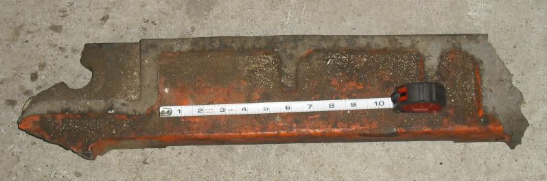
Mega Cyclone

Home Model Engine Machinist Forum

Help Support Home Model Engine Machinist Forum:

This site may earn a commission from merchant affiliate links, including eBay, Amazon, and others.

Powder keg

Well-Known Member
Joined
Oct 10, 2007
Messages
1,091
Reaction score
3
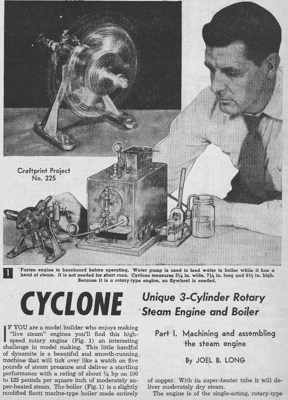
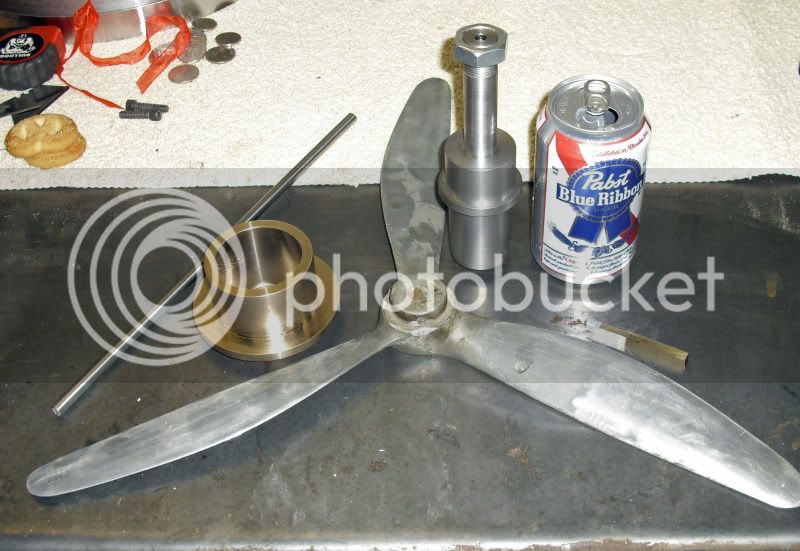
While cleaning up I found some Bronze that I had squirreled a way to build the Cyclone. I'm calling this engine the Mega Cyclone because I'm making this engine twice as big as the plans call for. I'll be changing a few Items to make it easier to build. But most of the parts will be as drawn. Just bigger:eek:) This engine is neat because the engine spins and the crank is stationary. I have a 19" 3 bladed prop that I'll fit to the engine. The pistons will be 1.250" in dia.

Here Is the first page from the plans.

Untitled-1.jpg


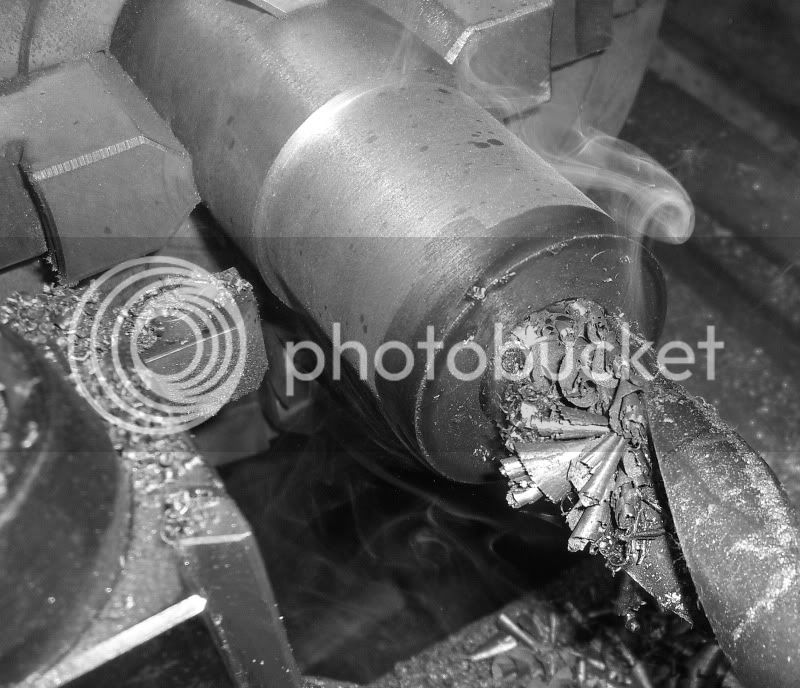
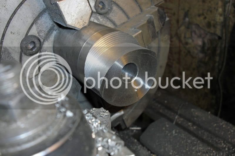
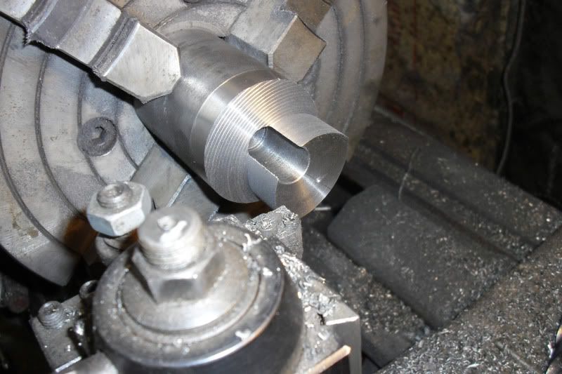
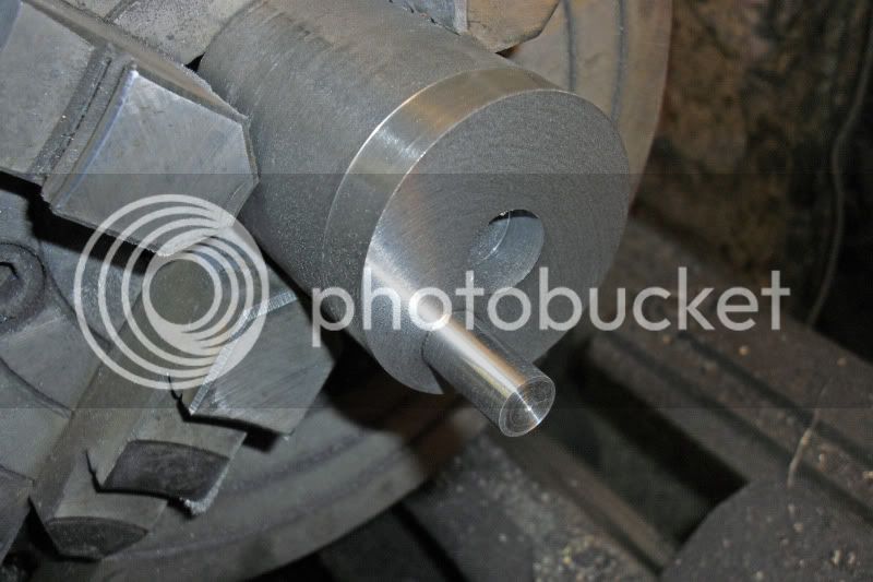
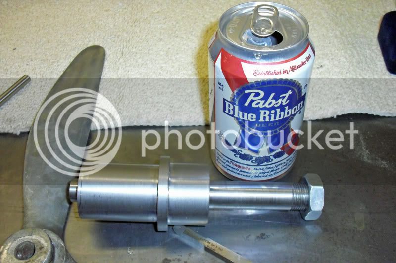
I have the crank valve turned. I'll mill the steam ports into it. The plans call for the ports to be made from a couple pieces silver soldered in. I think this will be easier? I left the bearing surfaces a few tho. Bigger and I'll turn them to size after the ports are milled.

Crankvalve001.jpg


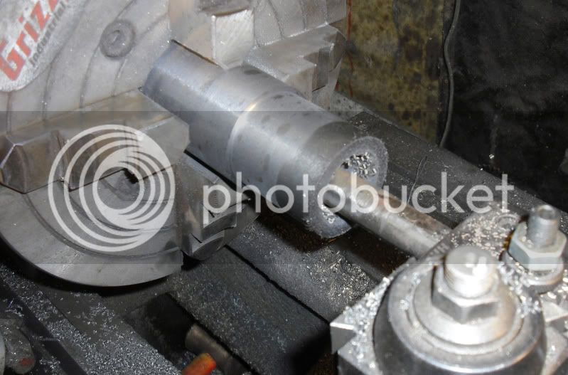
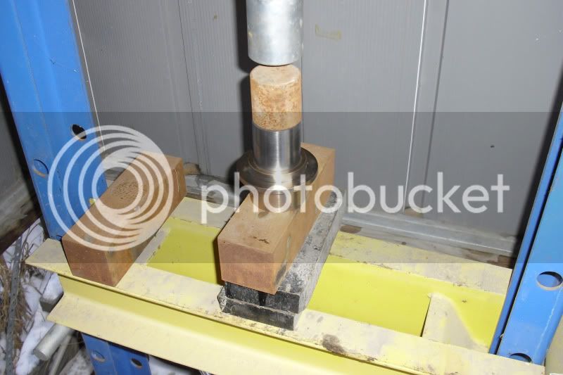
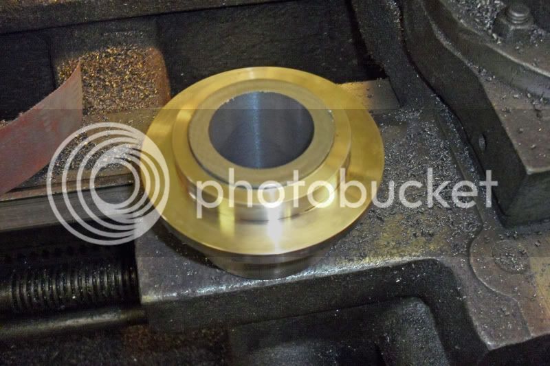
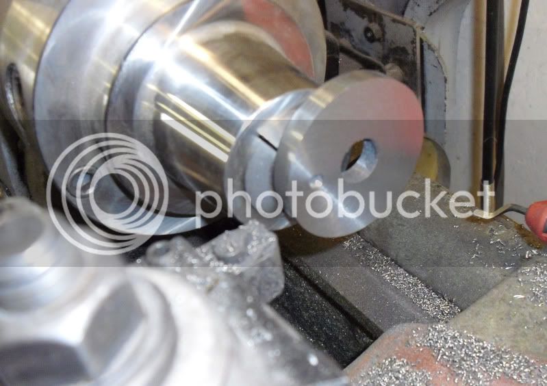
Here are the parts I managed to get turned today. The crank bearing housing will get a piece of cast iron pressed into it for the bearing.

Firstdayparts001.jpg


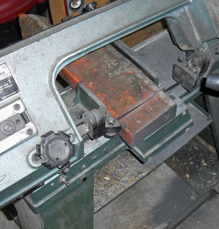
I'll start on the crank case next. These pieces will have a fair amount of mill work done to them.
 
Powder keg,

Where in the world did you find a Pabst can? Next is Reingold? Or Black Label?

Tony
 
Hi Powder Keg. Nice looking project, I like its old school look and feel.

Are the plans copyrighted, or can you disclose where they can be found, or looked at?

Thanks.

-MB
 
Have a whole cooler full of them Pabst cans:eek:)

The plans are from Popular mechanics maybe? Around 1952ish Maybe Mechanix illustrated. I don't remember. And I can't find the original:eek:(
 
cobra428 said:
Powder keg,

Where in the world did you find a Pabst can? Next is Reingold? Or Black Label?

Tony

A buddy up in Canada drinks 'Black Label', its been available. I remember seeing 'Pabst' recently in Cleveland Ohio stores. Never heard of 'Reinhold'. I stopped drinking a long time ago (shortly after prohibition was lifted, I think). ;D

Any way, back on topic.

Powder Keg, thanks for the info on the build plans.

I'm looking forward to following your build thread posts, good luck! :)

-MB
 
The plans were printed in Science and Mechanix in 1952. It was two articles the first was the engine. The second was the boiler. I'll make them into a PDF and put them in the plans section. The copies I have are OK. There are a couple of areas that are harder to read than the rest. I think I have it all figured out though. I'm redrawing most of the pieces to make it easier for me. I'll post those also.

Merry Christmas everyone!!!!!
 
I didn't get much done today. I did start roughing out the pistons and the crank bearing. I'm using some scrap cast iron. It turns out it's not the best quality though. It has a few inclusions/holes in it. I think it'll be OK though. There will be extra room for oil:eek:)

Here is the chunk I have. The Big CNC mill at work has a 5000 pound counter balance weight that holds the head up. The chain broke on it and it dropped. When it hit it knocked 2 of these off the base.

Castiron001.jpg


I'm cutting it up to make pistons out of.

Castiron002.jpg


I set them up in my 4 jaw and turned the pieces round. I'll press the bearing into the housing in the morning.
 
That's some hunk of iron, Wes.
More pics, (of pistons & such) please!

Dean
 
cobra428 said:
Powder keg,

Where in the world did you find a Pabst can? Next is Reingold? Or Black Label?

Tony

Hey! I know all of those brands!
I also know exactly where to find the Imodium tablets at the local drug store. ;)

You have my attention Wes.
Anxiously awaiting for the next update!

Rick
 
Wow, That's a whopper of a cast iron chunk! It looks like an awful heavy piece to lift, but after a little slicing and dicing it will lighten right up.

It's also my belief that the cast in porosity will help to hold a lot of oil.

I have the identical vintage of band saw, and I just couldn't be with out it. :)

Your project is very fascinating, I'll be watching with keen interest.

-MB
 
I'm glad there's interest. I think it is a pretty neat looking model. The way it works it should be terribly fast also? I don't have many pictures today. I mainly was making square bars into round bars on my old lathe. Pretty boring stuff. I can post a video? I'll start posting a bunch when the bars start getting turned into pistons and bearings and such. I want to make the cylinders then fit the pistons to them. So they will probably be next'ish:eek:) I tend to bounce around a little. But I'll get it.
 
As I recall, that type of engine was used in early WWI fighter planes. An unfortunate side effect was the gyroscopic force that made these planes very hard to land.
 
Regarding the use of that type of engine in a WWI airplane, I believe it was called a LeRohne Rotary. We had four rotary engines in the metal shop at my high school back in the mid fifties. The instructor had served in the RAF during WWII and would start them up once a year. He lived across the street from me and made sure that I was there when he did it. Also, as I recall, Cole Palen who operated the Old Rhinebeck Aerodrome in the mid sixties used to fly a reproduction WWI plane. The speed of the engine was controlled by shorting out the magnetos when you wanted to reduce the speed of the engine. The sound that it made when he was coming in for a landing made an old hit n miss engine sound smooth.
 
I managed to get all the square stuff turned round. Here I'm drilling out the crankcase bearing. i like Black and white machine shop pictures\o/

[ame]http://www.youtube.com/watch?v=ZqmruljZvpc[/ame]

Crankbearing001.jpg


Once drilled, I could bore it out. Since it will be pressed into the bearing housing, I left the bore small. I'll bore it out to size after it is pressed together.

Crankbearing002.jpg


I have a little press in the shed. Man its cold out there. I left about .003" interference between the two pieces. It took about 1000 pounds to assemble the tro pieces.

Crankbearing003.jpg


I cut the piece a little long on my bandsaw. I'll just trim it to legnth while I have it set up to bore it to final size.

Crankbearing004.jpg


I'll spend the rest of the day working on the drawings.
 
Powder keg said:
i like Black and white machine shop pictures\o/

Me too, sometimes. Reminds me of the good ol' days of HSM.
Thanks for the extra pics, Wes. This should be an interesting build to watch!

Dean
 
A few of the pieces on my version of the Cyclone I'm changing a little. The Crank Disc/Pin was drawn as two separate parts. I thought it would be more fun to make them as a single piece. I had a piece of that cast iron almost big enough. It's a little small on the OD, but it just has to keep the crank bearing on. I think it will work fine. It has a .750" "throw" so a one inch indicator was out of the question to indicate it in. I ended up marking out the center and using a center point out of a wiggler set to locate the center of the pin. I got the piece pretty close then I used a indicator on the shaft to dial it in. It's not the best way to do this, but it's all I had and I wanted to start cutting metal\o/

Here I am just starting.

Crankpin001.jpg


About half way through.

Crankpin002.jpg


Done!!!

Crankpin003.jpg


Ok, not done, done. But close. I need to drill a bolt hole in the center of the pin for a keeper. Then I'll saw it off a little long and face off the other side.

I took a short video so you could see some action. I'm taking .125" off the diameter here.

[ame]http://www.youtube.com/watch?v=KfpF10Js5pw[/ame]

More later.....
 
Nice work on the crank disc/pin, Wes. Thanks for action shot, too!

Dean
 
Thanks Dean!!!

I cut the crank disc/pin off the bar with my band saw. I then chucked it up, on the pin, in the collet chuck on my little South bend. I was able to face the part off to length pretty easily this way. I think I need to start on the base for this engine pretty soon so I have a place to put some of my pieces. Here is a quick picture. There is a hole all the way through the pin so the con rods can get a little lube.

Crankpin004.jpg


Thanks for looking.
 
I had to clean off my welding table for this shot. Here are a couple of the pieces for the base I'm going to build for this engine. The ring will be cut off at the white lines and the slug at the top will be machined and then welded to the arch. I still need to come up with some feet for the arch to be welded to.

Base001.jpg


This will give me a place to put my engine pieces:eek:)
 
Gonna be a nice looking engine. That's gonna be a pretty big chunk of spinning metal when you get it fired up. However, I don't think balance and vibration is much of an issue with rotary engines. Have you figured out about what the total diameter will be?

Chuck
 
Back
Top