Mechanical Clutch

Home Model Engine Machinist Forum

Help Support Home Model Engine Machinist Forum:

This site may earn a commission from merchant affiliate links, including eBay, Amazon, and others.
Making the endblock in two pieces is the only way I can make this part.
ENDBLOCK-1_zpsbfdbd80b.jpg

ENDBLOCK-2_zps9cdde4d9.jpg
 
Wanting to do this in as few set-ups as possible, I clamped a 2" x 1" x 12" piece of aluminum bar to the mill table with a 1/4" spacer bar under each end. This was to raise the piece being machined up of the mill table so I could drill thru it without damaging the mill table. I aligned it very carefully with the right to left axis of the mill and then cut away two areas to the finished thicknesses of .938" and .813", both about 3/8" longer than the part it would make. Then all bores except one and all bolt holes and tapped holes were done without having to move the part. I also milled away the 1" x 3/16" x 2" relief on the mating faces while in this set-up. The faces which were machined will face each other when the two parts are seperated and bolted together. Of course that means that there is one bore which will be on the far side as well as 4 bolt counterbores. I will flip the part over, pick up position off of the .75" reamed hole, and then put in the final 1.5" dia. counterbore and the c'bores for the bolt heads. I hope I have this sequence figured out correctly, and it seems to be going okay so far. I will use the round piece that registers in the .75 bore and the 1.5" bore as an alignment tool when bolting and doweling the two pieces together.
firststep-endblockmachining001_zpsa9d3a7ec.jpg

firststep-endblockmachining002_zpsb99c4e38.jpg
 
Happy New Year everybody!!! Things keep moving along, and as the work progresses the design keeps evolving. These drawings are current and will not change, because the parts are made and assembled. I will be posting a video a bit later today of this actuating mechanism working.
ENDBLOCK-2_zps287759a3.jpg

CLUTCHPRESSUREMEMBER_zps26175486.jpg

BUSHING_zps318a39de.jpg

ENDBLOCK-1_zps28f14b41.jpg
 
Here is a rather shabby quality video of the clutch actuator working. I am fighting with my camera today, and this is the best of 3 videos I made of the same thing. Its not great, but it does show the action very well.----Brian
 
This is the last part I have to make, other than the shaft and the final pulley (which I will change to a double groove). I finished the part this morning that looks like a large pillow block bearing, all except for rounding the top, which I do on my big stationary belt sander out in the main garage. However, wife and I are both sick with the cold. I'm recovering, she's in bed----And her bedroom is right above the main garage. I won't be firing up the big belt sander until wife is up and about.
BASETIEPLATE_zps158009dd.jpg
 
Almost finished!!! I have to make a pulley for the outboard end and put a slot in the shaft, thats all. What about the gap?--Oh, that gap. Well---I left the oak about .080" longer than what the drawing called for, to give me some "extra" friction surface to wear away, then went and built that bottom plate to the blueprint. Thats okay. I sort of figures there would be some fine tuning when I got to this stage of things.
CLUTCHALMOSTDONE-2001_zps0cfbcc1b.jpg
 
Brian, that's an interesting piece you have there. I'd be interested in seeing just how it performs.

It could be useful for many things and if scaled up a little, I can see a use for it on my Chinese lathe ;)

Loved the video too, more please! :)
 
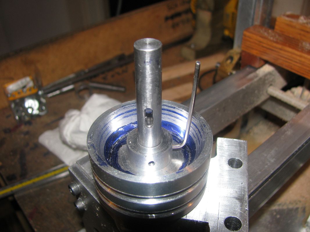
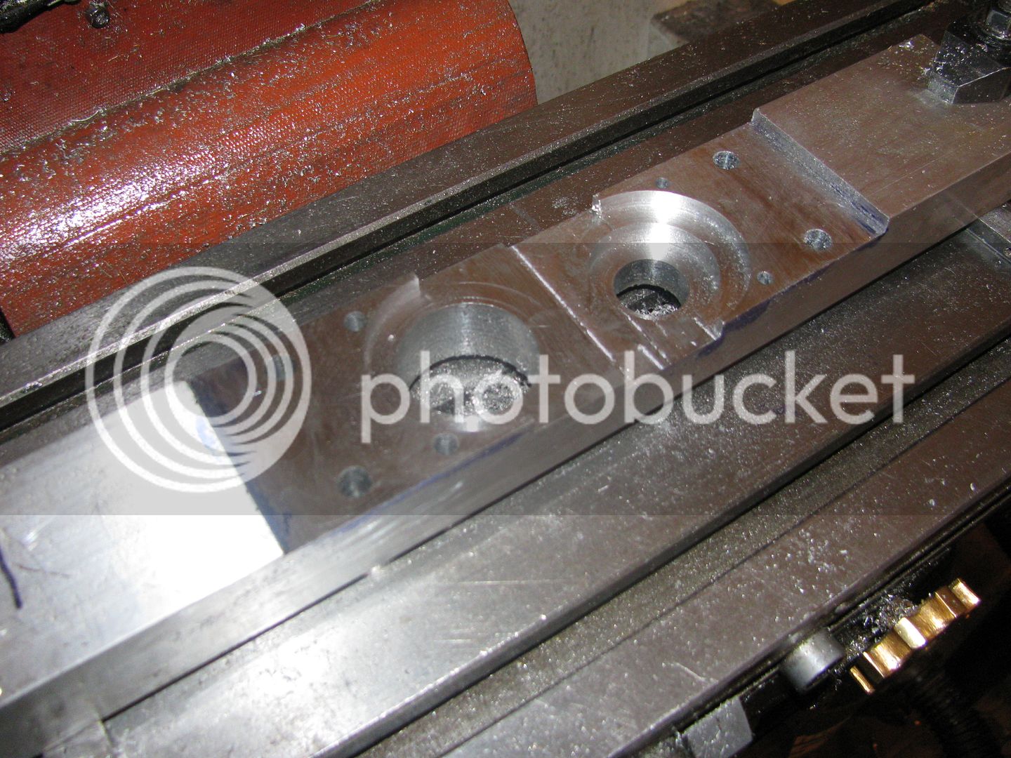
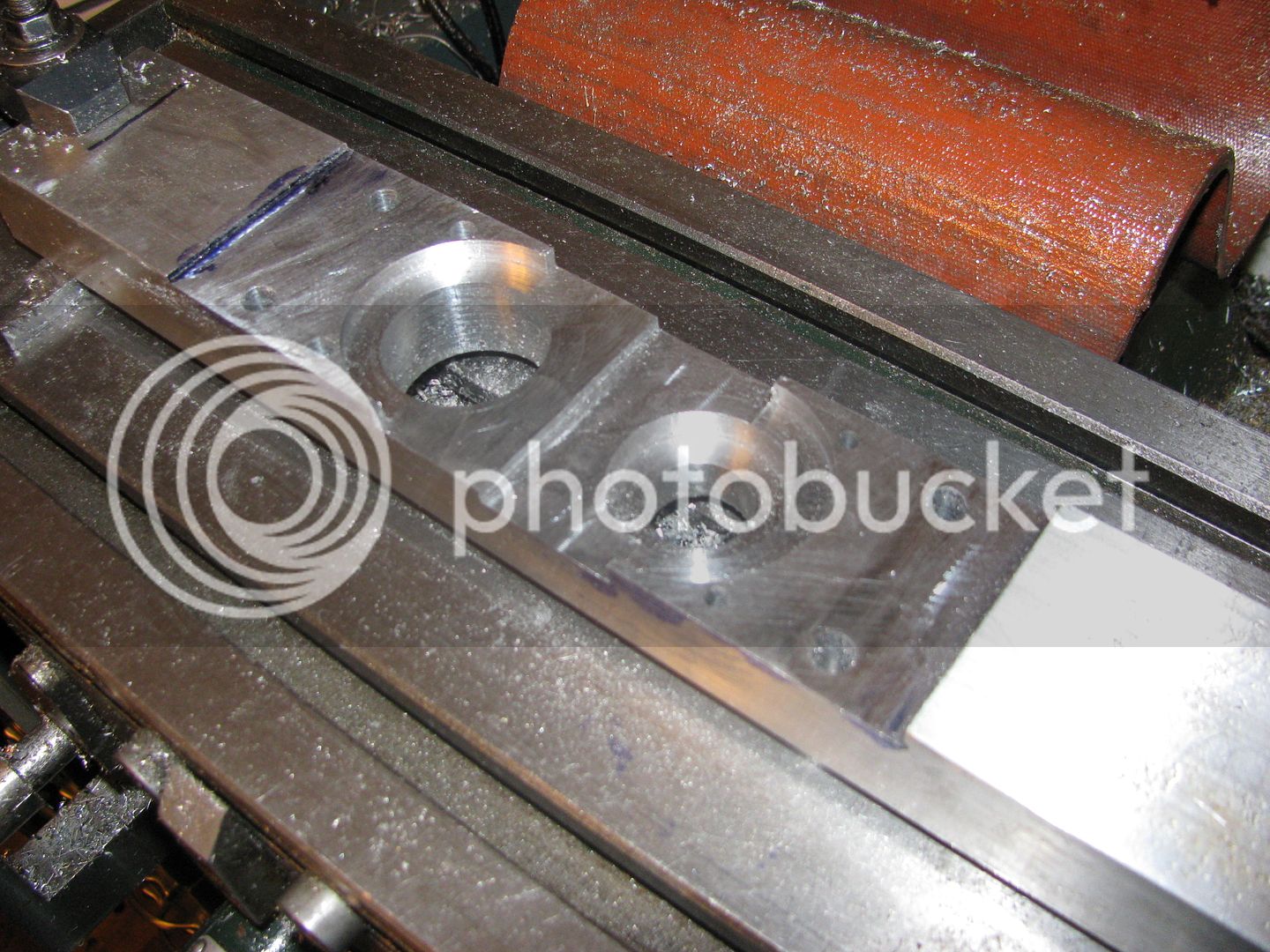
looking at the pattern of dye marks in the femeale cone, of the same "thead" than the top slide screw I bet, a setting of the top slide will reduce this wobbling, if the slides are worn regularly along their ways... turning a morse cone in my lathe is now impossible without a major overhaul of the topslide, someday, but morse cone are not that expensive...
Cheers
I'm fond of yours thread, all of them, awsome engines.
 
Thanks for looking and commenting, fellows. I will be finished with the clutch this week, and will definitly post a video of it in operation.
 
How do you put a 3/32" slot thru a 3/8" diameter steel shaft?---Answer: The same way porcupines make love.---VERY carefully!!! I drilled thru the shaft at what would become the ends of the slot, then walked a 3/32 carbide endmill back and forth taking about .010 doc each pass. Held my breath the whole time, but it turned out okay. I thought I was ready for final assembly, then realized that I still hadn't made the 3/8" diameter shaft collar that prevents the pulley part of the clutch from following the friction disc along the shaft when the clutch is disengaged. Then after taking another look at the assembly drawing, I realized that if I put a set screw thru the outer diameter of the collar the normal way, I wouldn't be able to get at it to tighten it up unless I drilled an access hole thru the face of the pulley. I will look at it more closely tomorrow. I may have to put the set screw thru from the side at an angle. At any rate, here is a picture of all the parts except the shaft collar and the outer pulley.
SLOTINSHAFT-2001_zpsc2fdec2b.jpg
 
Just enough room--barely, barely---with a cut down allen wrench, to reach in and tighten the screws in the shaft collar.
JUSTENOUGHROOM002_zpse5536e8f.jpg
 
Its hard to see in the picture, but this drawing will clear it up some. That piece with the set screws in it is a seperate piece altogether. It was fully machined, then slid over the shaft into position. It shows up as the red part in the drawing.---Brian
ASSYOFCLUTCH_zpsc1e07c93.jpg
 
The clutch works!!! At least it works as near as I can tell by turning the shaft with a pair of vice grips while engaging and disengaging the handle and holding the cone-pulley with my OTHER hand. Yeah, I know. Thats 3 hands!!! Can't really tell a lot until I get this pulley made and get things hooked up with my o-ring drive belts.
DRIVENPULLEY_zps3d616983.jpg
 
Teaser shot!!! I haven't tapped the set screw threads in the pulley yet, but I just had to see what it looked like. The outer pulley is driven, the inner pulley is the clutched pulley. Although, I suppose it could just as well be the other way round.
TEASER002_zpsf0be1055.jpg
 
Here we have the promised video of the clutch in operation. Bear in mind that the clutch is brand new, and consequently a bit stiff untill it gets ran for a while and loosens up. The sawmill takes very little power to drive it, but the stiffness in the clutch is the reason that the electric drill was working as hard as it appears in the video. Once this clutch mechanism is fully "run in", it will take very little power away from the engine it is used with. My trusty Canon digital camera has crapped out on me, so I just went and bought a Sony DSC-H90 to make this video.---Brian
 
Very nice Brian. Your saw mill must really be built well to be able to take a cut that only produces sawdust the width of the blade and not wander out of the kerf. Good job!

Pat
 
Very nice Brian. Your saw mill must really be built well to be able to take a cut that only produces sawdust the width of the blade and not wander out of the kerf. Good job!

Pat
Pat---I hadn't even noticed that. I had to play the video over again to see what you were talking about, and you're right, it was shaving off a cut the width of the blade. I have the clutch working much more freely now. I put a v-belt bulley on it and set it up with a belt drive from ny lathe and drove it at 550 rpm for about 20 minutes to take the stiffness out of it. Its too cold out in my big garage to mess with the atkinson engine now, but when the weather warms up (which may be the end of March) I hope to make a video of the sawmill cutting a log driven by the Atkinson thru the clutch.---Brian
 
Back
Top