But the oak was FREE!!!---And I'm just guessing at the cone angle.
You are using an out of date browser. It may not display this or other websites correctly.
You should upgrade or use an alternative browser.
You should upgrade or use an alternative browser.
Mechanical Clutch
- Thread starter Brian Rupnow
- Start date

Help Support Home Model Engine Machinist Forum:
This site may earn a commission from merchant affiliate
links, including eBay, Amazon, and others.
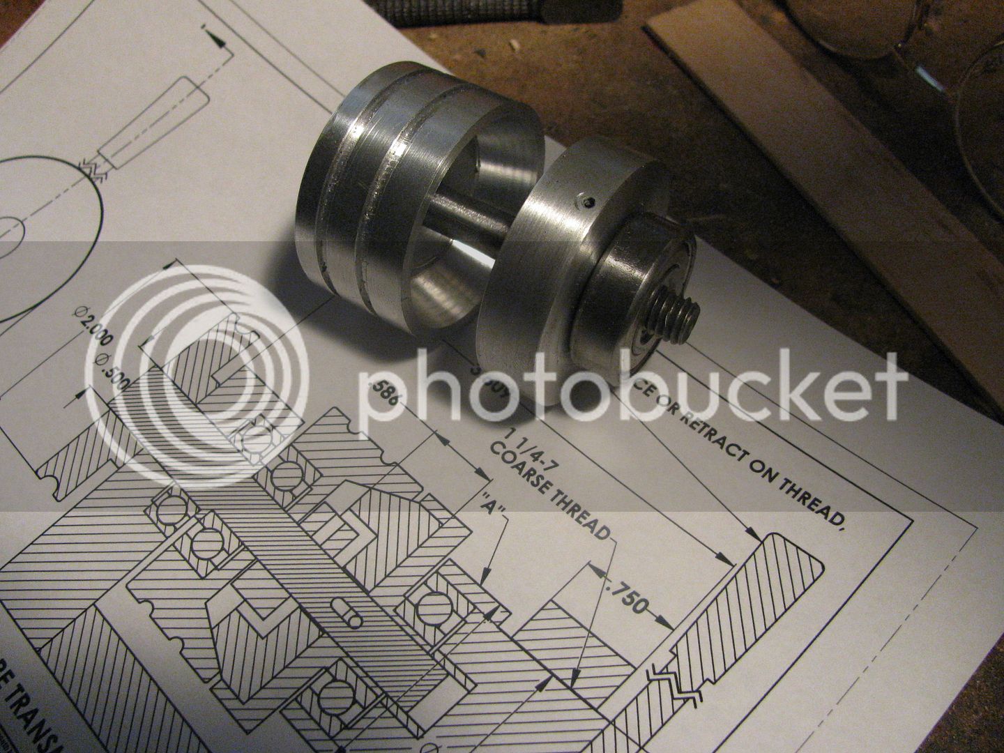
There----Thats the outer clutch housing finished. I did manage to get a much better fit on the bearing this time. I lined both pieces up on an old 3/8" bolt to take this picture, as I couldn't find a piece of 3/8" cold rolled. Maybe I will have time to make the oak friction cone and epoxy it in place later today. Gotta go now and do Christmas things.

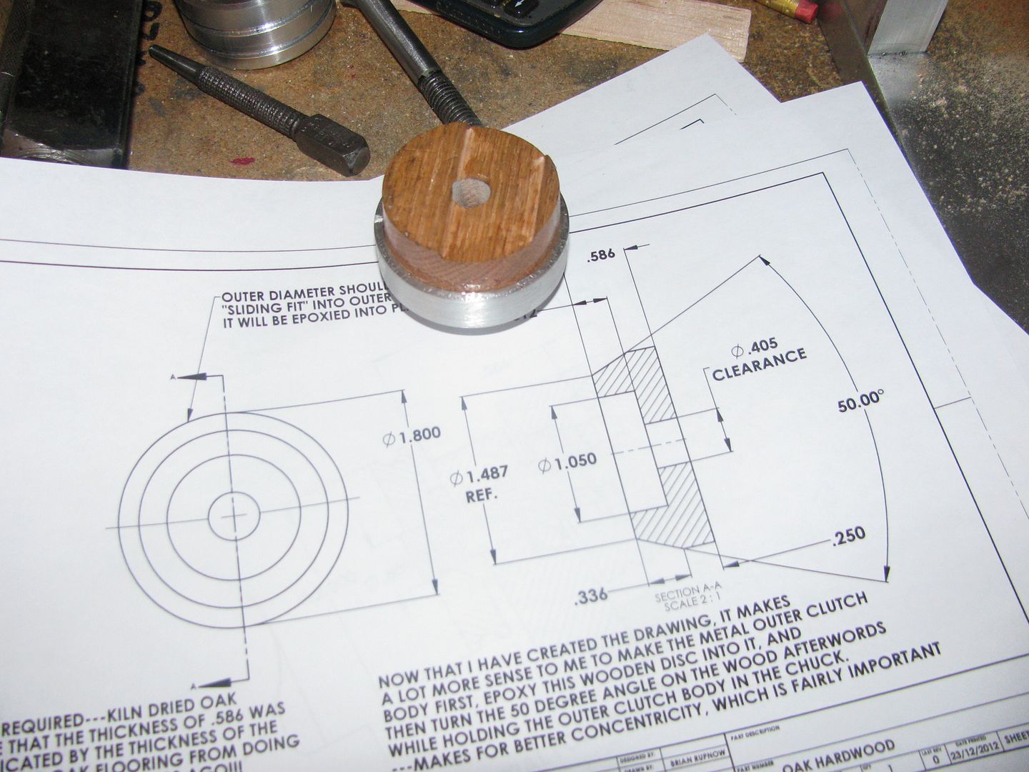
The oak, turned to correct o.d. and epoxied into the outer metal housing.

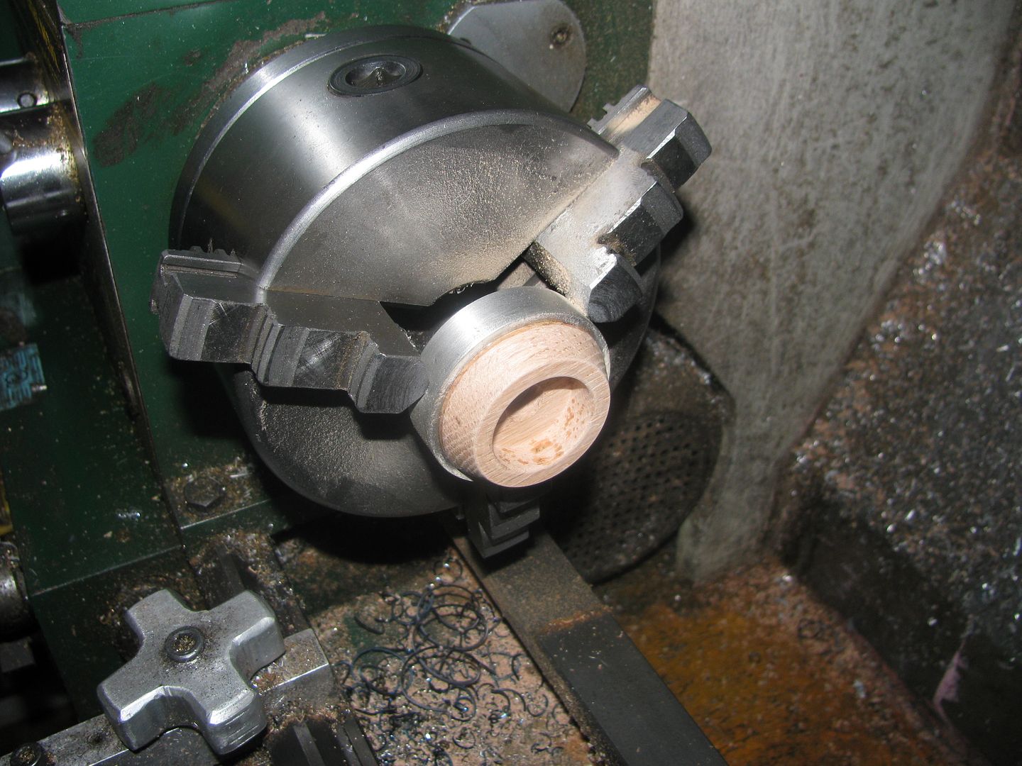
The oak machines very cleanly at 1620 rpm, with HSS turning tools and/or carbide boring tools.

kutzdibutz
Well-Known Member
- Joined
- Feb 16, 2012
- Messages
- 74
- Reaction score
- 28
Brian,
very good to know! I would have expected a dedicated cutting angle to be required to cut wood properly. Very good to know it works with the 'standard' tools.
Cheers, Karsten
very good to know! I would have expected a dedicated cutting angle to be required to cut wood properly. Very good to know it works with the 'standard' tools.
Cheers, Karsten
I have machined oak before, for some of the wacky things I build, and I too was surprised by how cleanly it machines with my standard tooling. I think the fact that it is a hardwood and the high rpm are the ticket. I have tried machining softer woods like pine, but the tools must be razor sharp to get good results.
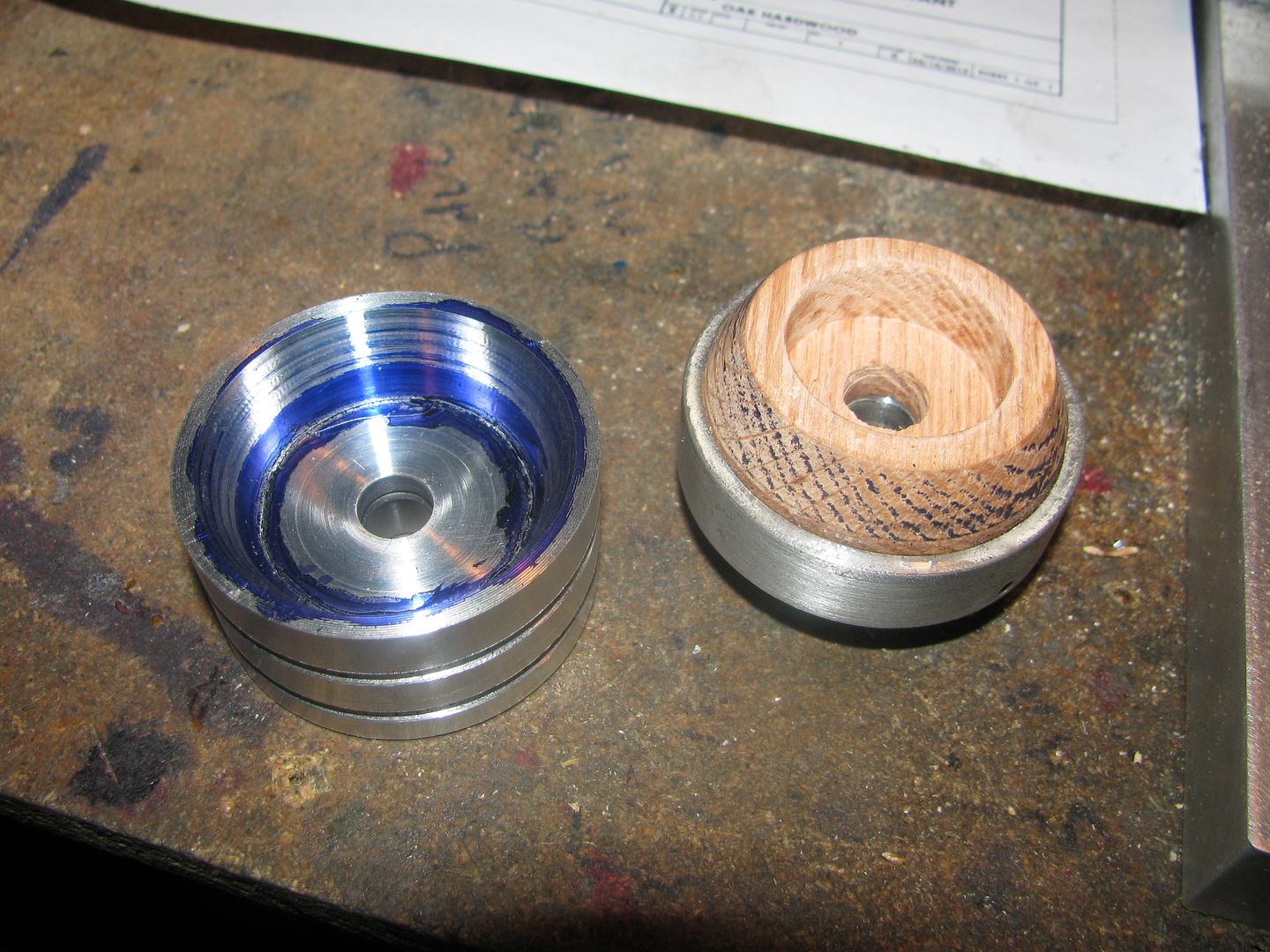
I "blued" the inside of the metal cone with some Dykem layout dye, and after it had completely dried I set up both parts on a 3/8" alignment shaft and spun them in opposite directions by hand. The initial results appear very good. I had to swing my topslide over to the opposite side to turn the oak, and I set it to 25 degrees by the protractor built into the topslide. The protractor is marked in 1 degree increments and is only slightly better than a guess. I know that if things weren't perfectly concentric, they would be after the first 5 minutes of actual use. From the pattern I see where the Dykem wore off the aluminum and onto the oak, I think I got it pretty close.

This morning I made up a drawing of the main support bearing. More to determine whether I have a piece of material big enough or not.
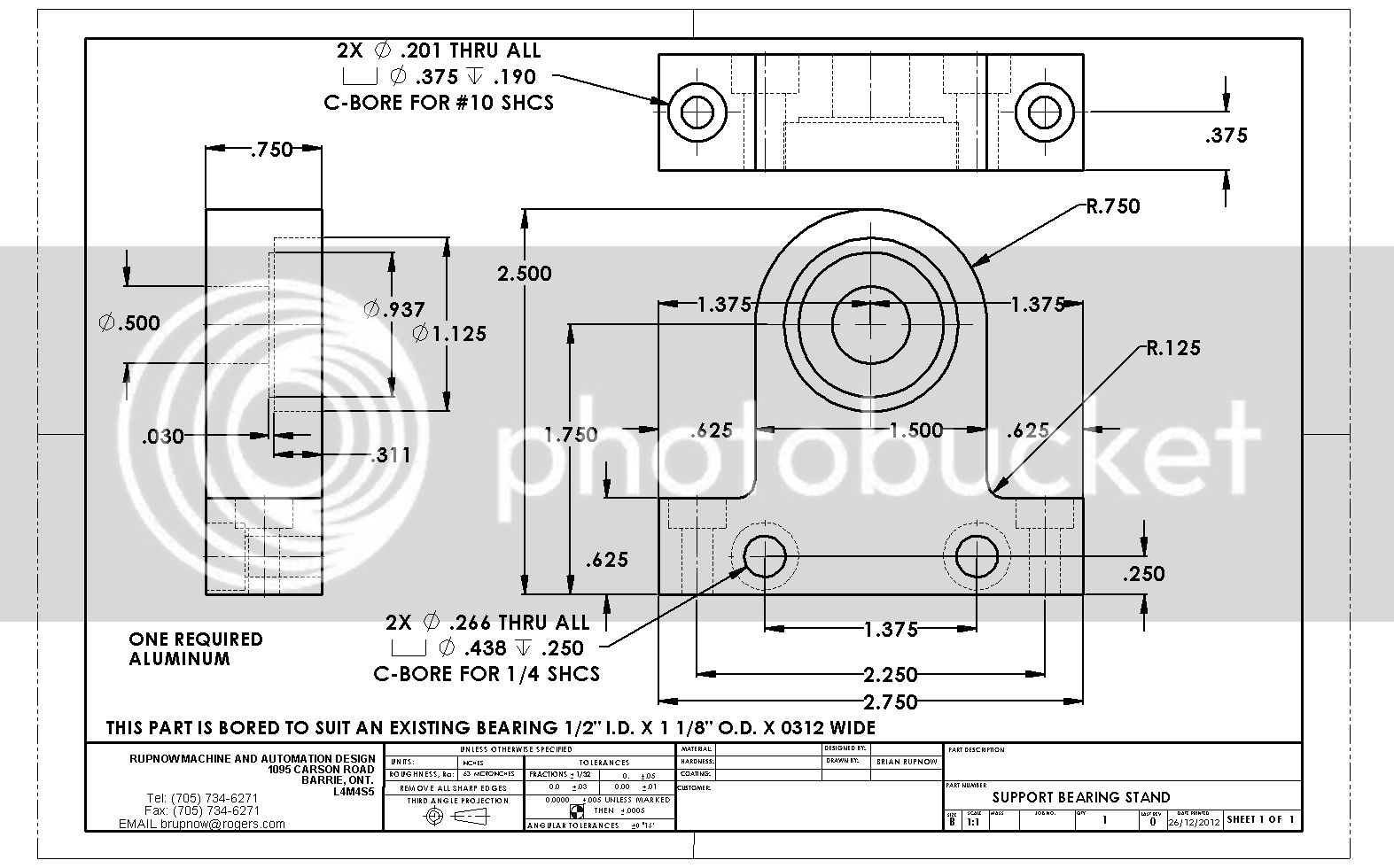

Well. no 3/4" plate, but I did find a chunk of 1" aluminum plate big enough to carve this from.
Thru good luck, 4$, and some creative begging I was able to scoop a 1 1/4"-7 hex nut and about 3" of threaded rod this morning. I keep changing the right hand end of the clutch, and refining it so that none of the rotational moments feed back thru to the thread which forces the clutch faces together. The wood in the background is boards sawn from my model sawmill.
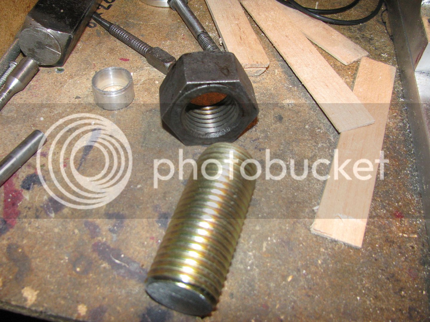

Sometimes I think that the quality of my life would improve if I could cut single point threads on my lathe!!! However I can't. First it was learners inability, Then somehting went crunch in the leadscrew drive. So----I live with work arounds.
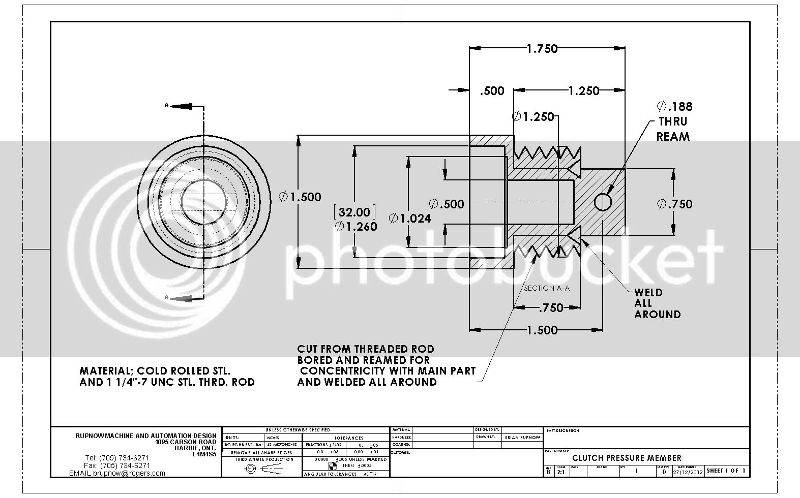

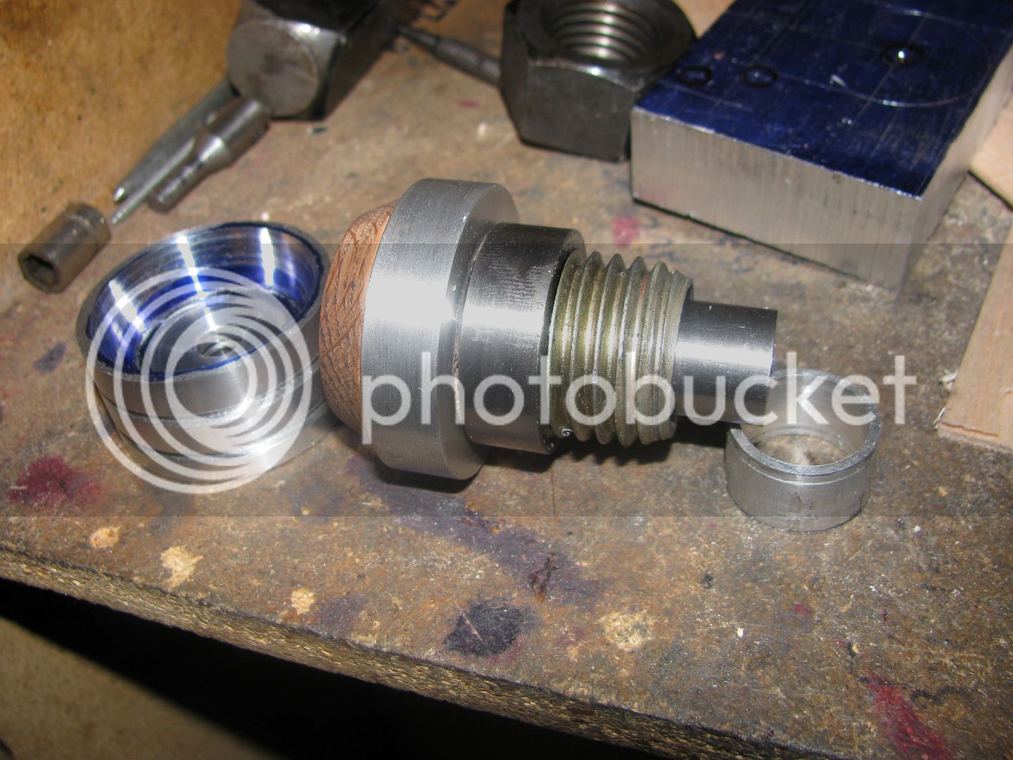
I just finished the part which "activates" the clutch cones, to move them together or apart. I was going to weld the threaded portion to the turned portion of shaft, but found out that the piece of what I thought was 1 1/2 diameter steel was actually cast iron. Thats okay though. Since the threaded portion sets up against a shoulder when the clutch is being engaged, Loctite 638 will suffice to keep the two pieces together. The cross hole for an anti rotation pin has not been drilled yet.

Last edited:
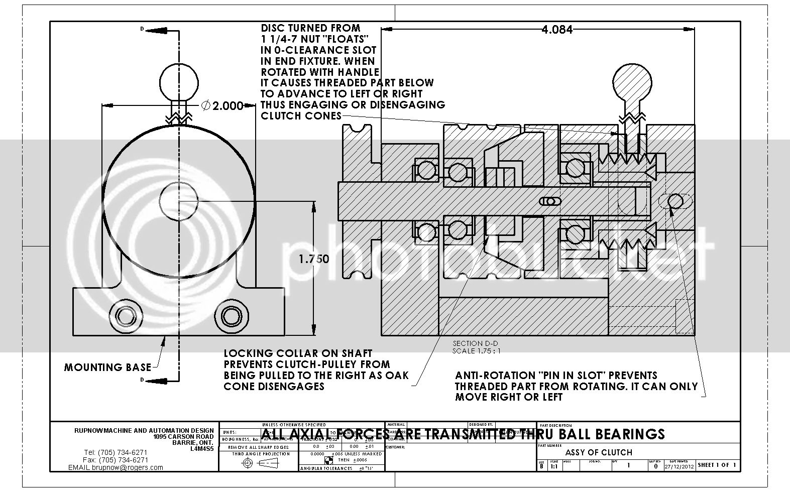
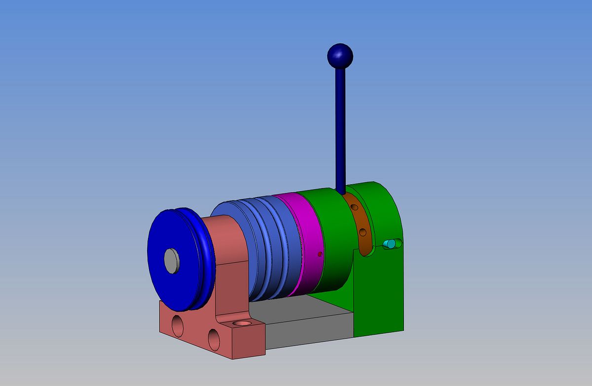
The design of the right hand end of this clutch mechanism keeps evolving, as I think of potential problem areas and ways to overcome them. This is the latest vesion, in which the part with the external thread on it has an anti rotation pin riding in a slot, so that none of the rotational moments up at the "cone" end can be transferred to the part with the external thread, causing it to tighten or loosen by itself.


mygrizzly1022
Member
- Joined
- Sep 4, 2010
- Messages
- 75
- Reaction score
- 7
Hi Brian
I am having a hard time believing that single point threading and a Crunch could possible intimidate you. The tenacity with which you pursue your various projects is such that the threading issue complete with Crunch should provide a miniscule challenge.
I look forward to your thread on Beating the crunch. The lathe you have seems to have a reasonably good reputation as does the Bee so my guess is once you attack it, you will win, and work a rounds will not be necessary.
Regards Bert
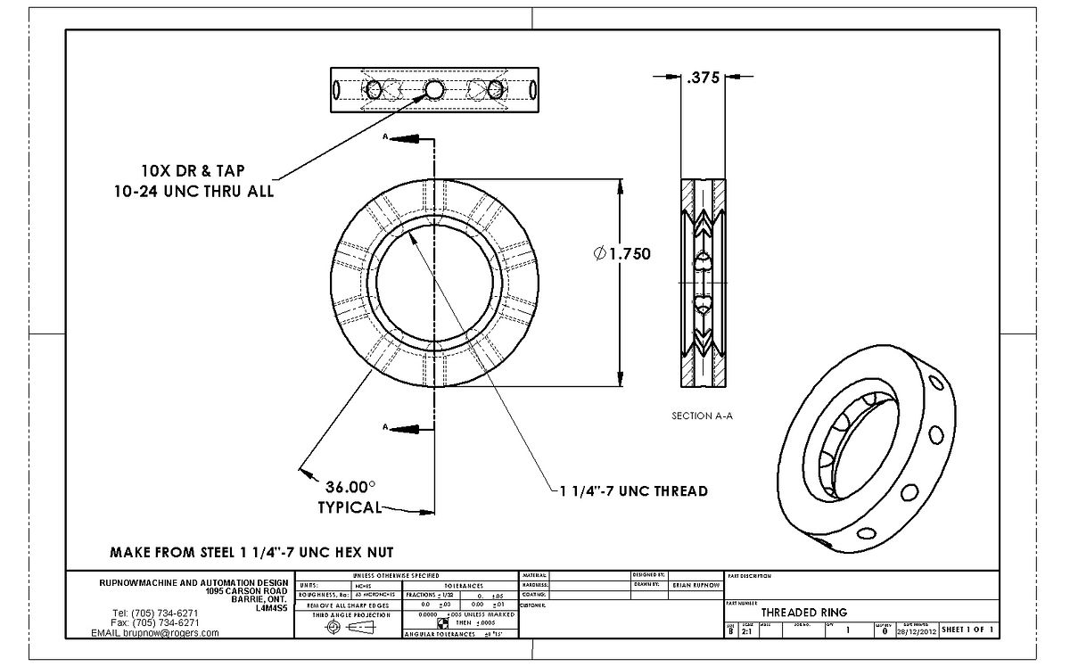
This is where I'm going next---

Bert---The reason that I haven't persued this issue is that the lathes lowest speed is 115 rpm, and thats simply too fast to thread with. And I believe that on this lathe, to reverse it, you have to shut off the motor, reverse it, and then restart the motor.Hi Brian
I am having a hard time believing that single point threading and a Crunch could possible intimidate you. The tenacity with which you pursue your various projects is such that the threading issue complete with Crunch should provide a miniscule challenge.
I look forward to your thread on Beating the crunch. The lathe you have seems to have a reasonably good reputation as does the Bee so my guess is once you attack it, you will win, and work a rounds will not be necessary.
Regards Bert
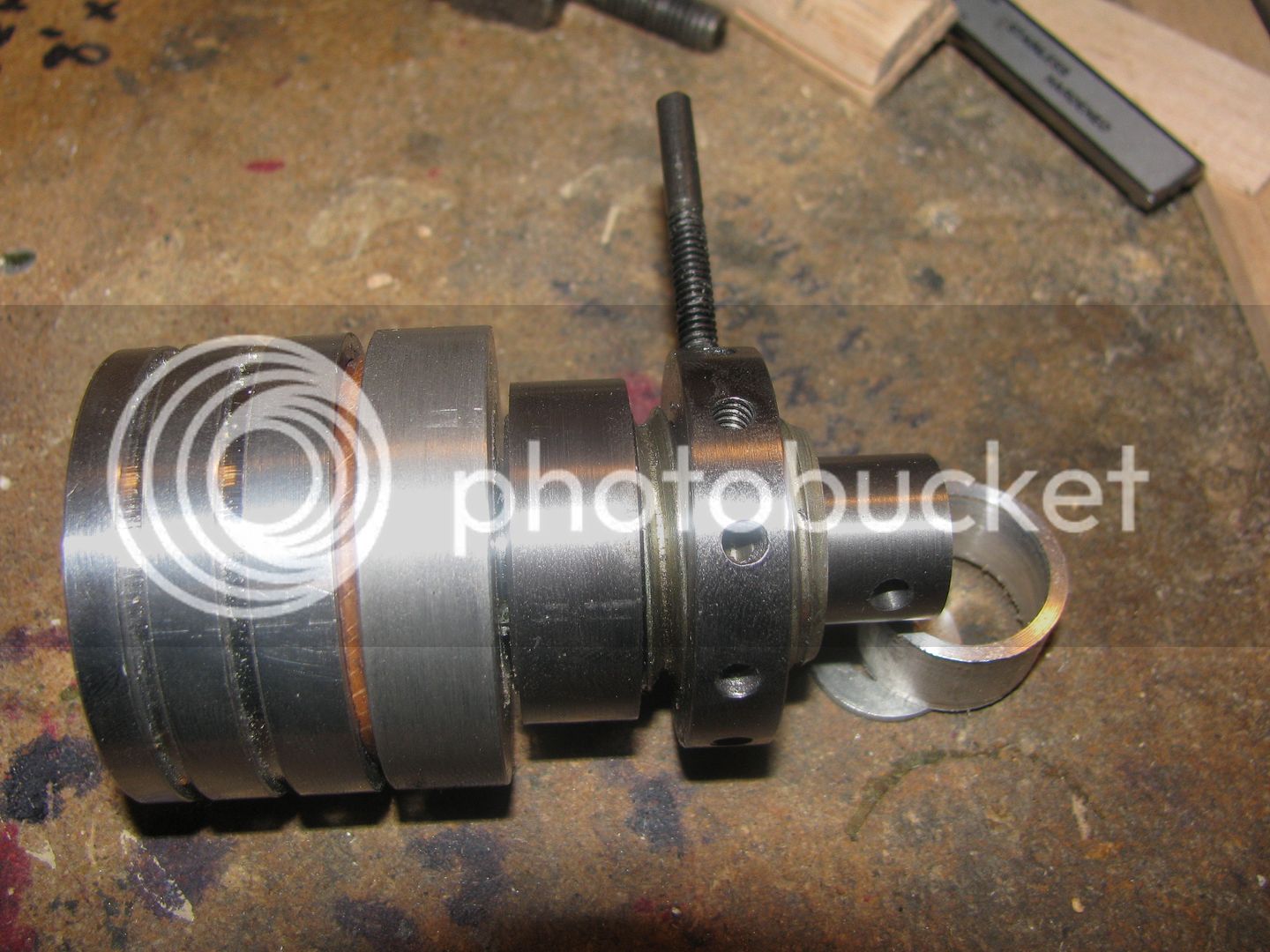
Well, is it starting to look interesting yet? Thats all the internal parts finished. The #10-24 threaded rod screwed into one of the tapped holes in the ring was just there to give me a temporary handle to see how smoothly things turned. While I had the rotary table set up, I also added the 3/16" hole for the anti rotation cross pin in the part which I made earlier today.

starnovice
Member
- Joined
- Nov 21, 2010
- Messages
- 194
- Reaction score
- 23
Very interesting Brian. When it is done maybe you can connect it to the sawmill to demonstrate it.
Pat
Pat
Starnovice--Thats been my intent all along. I want to use the Atkinson as my power source, but I don't want to have to stop and start the engine. If this clutch is succesfull, I can leave the engine running while I do any tweaking I want to with the sawmill, then engage the clutch and have the engine saw under power.Very interesting Brian. When it is done maybe you can connect it to the sawmill to demonstrate it.
Pat
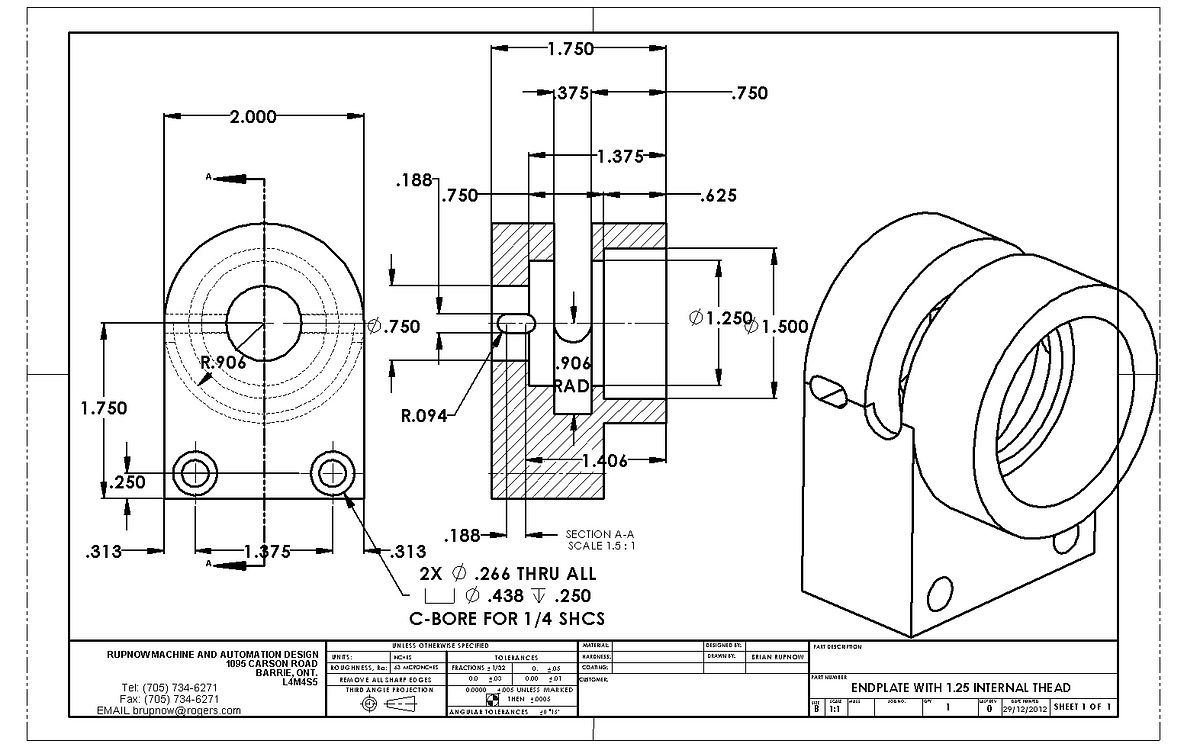
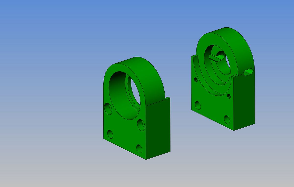
In my great surge of creativity and rush to complete the mechanical clutch, I did the unthinkable!!! I designed a part which, although it looks just great, simply can't be built with the tooling I have. That cut out in the center with a 0.906" radius is impossible for me to machine. The design engineer thought it made perfect sense. The machinist looked at it and after studying the drawing for a few minutes said "How in H%$# am I supposed to machine that???" So---The design engineer sat down, screatched his head for a while, and said "I Know!!! We'll make it in two pieces with the split line right on the center of that .375 width and bolt the two peices together with a couple of alignment dowels to keep everything concentric. And thats what he did!!! (The alignment dowels are not shown in the solid model.)


Similar threads
- Replies
- 61
- Views
- 8K
- Replies
- 37
- Views
- 11K


