Steve and the other Bob,
Thanks guys for your continued interest and support. :bow: :bow: Yep, bigger than Ben Hur. ;D
kvom said:
Newbie question on gudgeon (wrist) pins in general. Since you have a lock screw it is evident that as the piston moves the pin must oscillate in the side walls of the piston. Should I assume that the bronze of the piston acts as bushings?
On my smaller CO2 engine, the plan has the piston rods moving over a stationary gudgeon. I am wondering if there will be a problem with the piston rod walking sideways. If so, I imagine I could make some brass bushings to keep it in the center. Thoughts? FWIW the diameter of the pistons is 3/4". The wrist pin is 1/8" diameter rod (could be drill rod or brass).
Kvom,
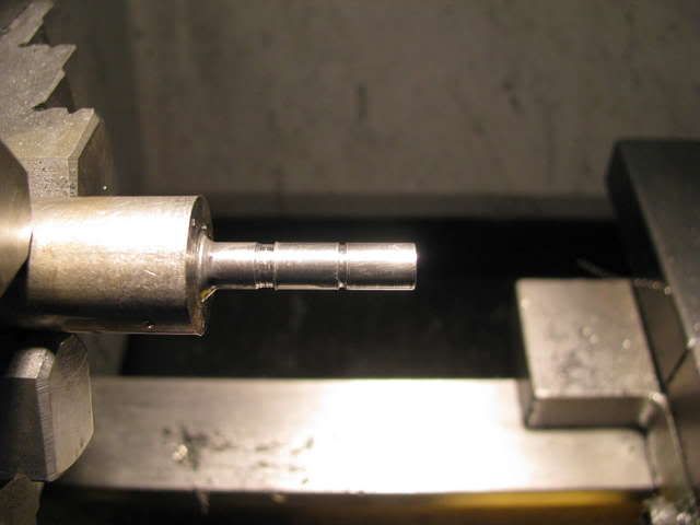
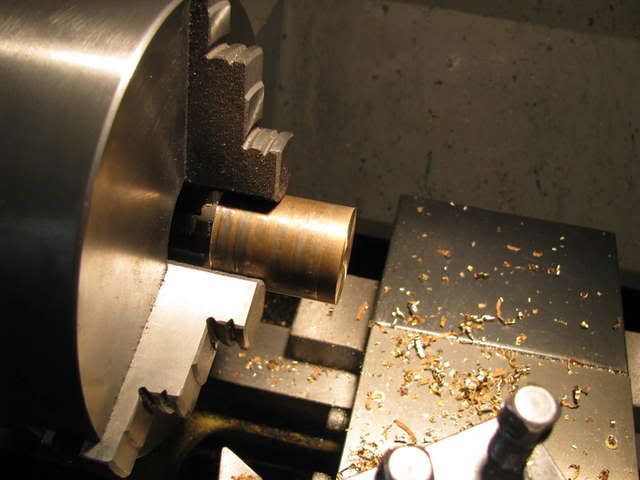
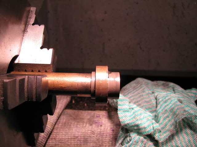
1 Above, yes the gudgeon/wrist pin oscillates in the piston. In this case 316SS against t200 cast iron. I was originally aiming for a fully floating setup with circlips to prevent sideways movement of the pin. I settled for the above as being far easier to machine and secure. I need not have placed a bronze bush in the gudgeon/wrist pin end of the conrod with the method I ended up with.
")
2 Above, your mechanism is the 3rd option of those used for conrod oscillation. Maybe you could lock the pin with a screw from the underside of the piston. Maybe you could shorten the pin a little and fill the ends with soft solder. Last but not least, if your piston has rings one of the latest innovations, (12":1ft), is to put aluminium end caps on the pin which if it moves pushes the aluminium against the cylinder wall. Can't say I'm all that thrilled about the idea but it's out there working so there must be something to it.
And..... thanks for your support and Interest. :bow:
steamer said:
Yes Steve makes a great point.......WHEN it starts Bob ;D.....make sure we don't end up calling you "fingers", as I assume your putting a prop on the front of that beast?
Knowing something of your past endevors....I have every reason to believe that won't happen....you've been around big stuff far to long to be careless now!
Thanks Dave, :bow: I've broken a few on the way by dropping boiler doors on them, (just as well I'm not a concert violinist :
), but I've managed to keep all my digits, (all 21 of them).
I think attempting to run this thing will be an outside job with a substantial mounting block and a couple of bloody great clamps.
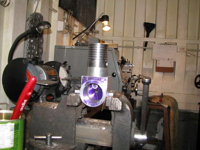
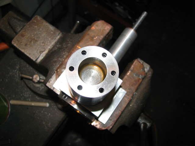
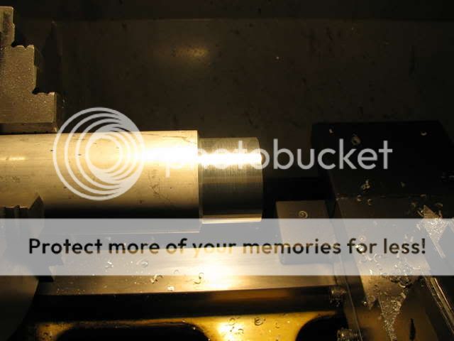
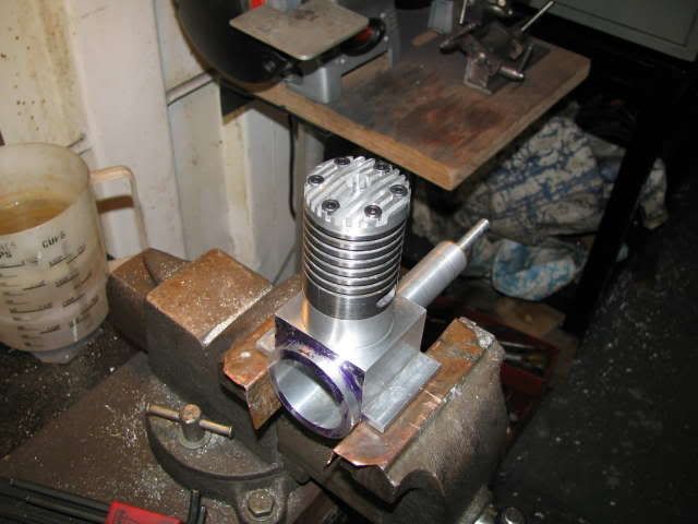
Below is today's effort.
Some Aluminium for the cylinder head.
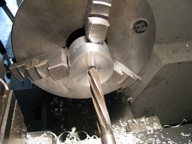
Reaming the centre hole for the compression screw plug.
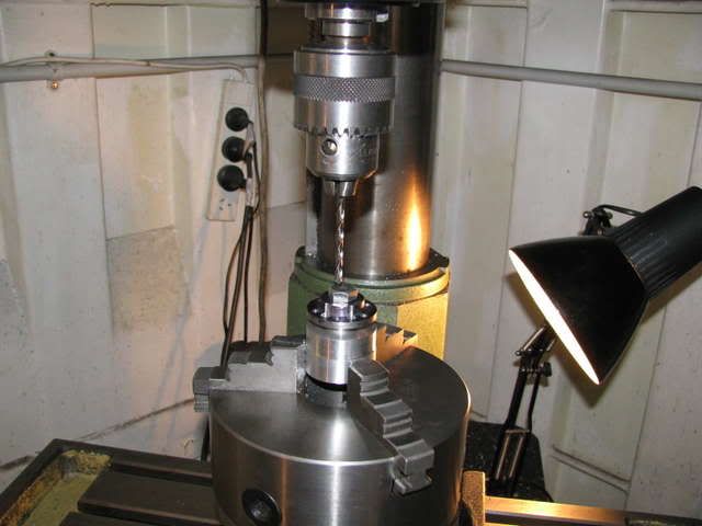
Drilling for the head bolts.
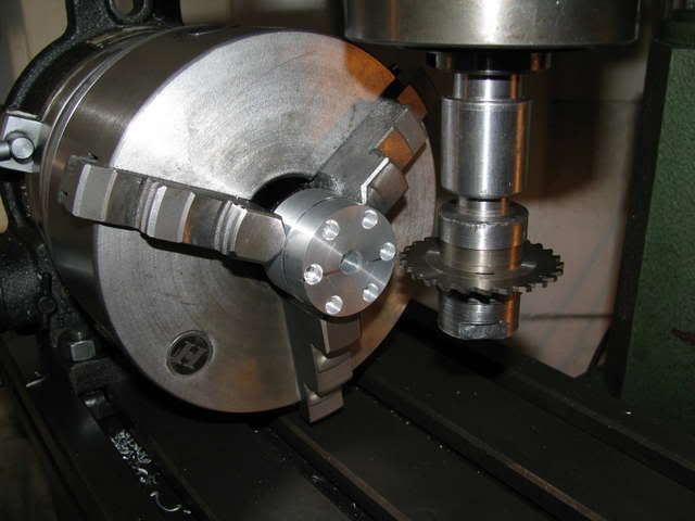
Set up for machining the cooling fins.
Last but not least, I finally received my Xmas present from my daughter, (its' been on back order).
Now I will have to expend extra energy and impose self discipline to finish M10 before delving into gas engines and electrics.