Marklin 4148/4149 rebuild

Home Model Engine Machinist Forum

Help Support Home Model Engine Machinist Forum:

This site may earn a commission from merchant affiliate links, including eBay, Amazon, and others.

Kaleb

Senior Member
Joined
Jan 3, 2010
Messages
272
Reaction score
27
If you haven't heard how this engine came to my workshop, you can read about it here: http://www.homemodelenginemachinist.com/showthread.php?t=27760
Long story short, it actually belongs to a man in Ballarat, and was damaged in a fire.


I originally had no idea what model this engine was, except that it was a Marklin, but a contact of mine managed to identify it as either a 4148 or 4149. Does anyone know which of those two this one is, or what the differences between the two models are? Either way, I will need some assistance as a number of parts are missing, which I will be making myself as I believe spares for these engines are as rare as hen's teeth.


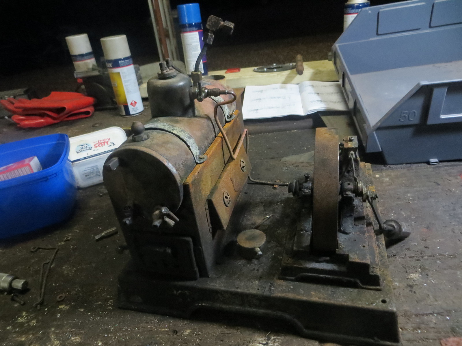
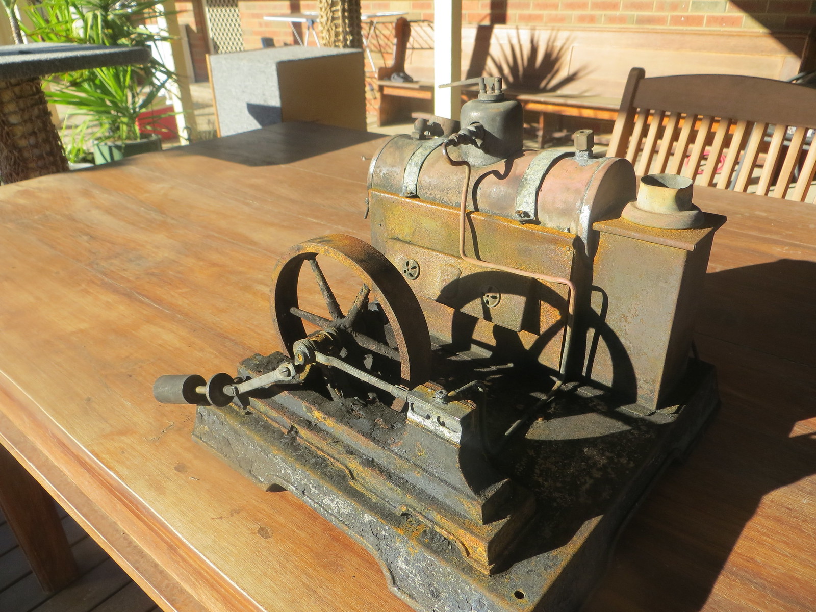
The engine in the workshop about to be stripped down


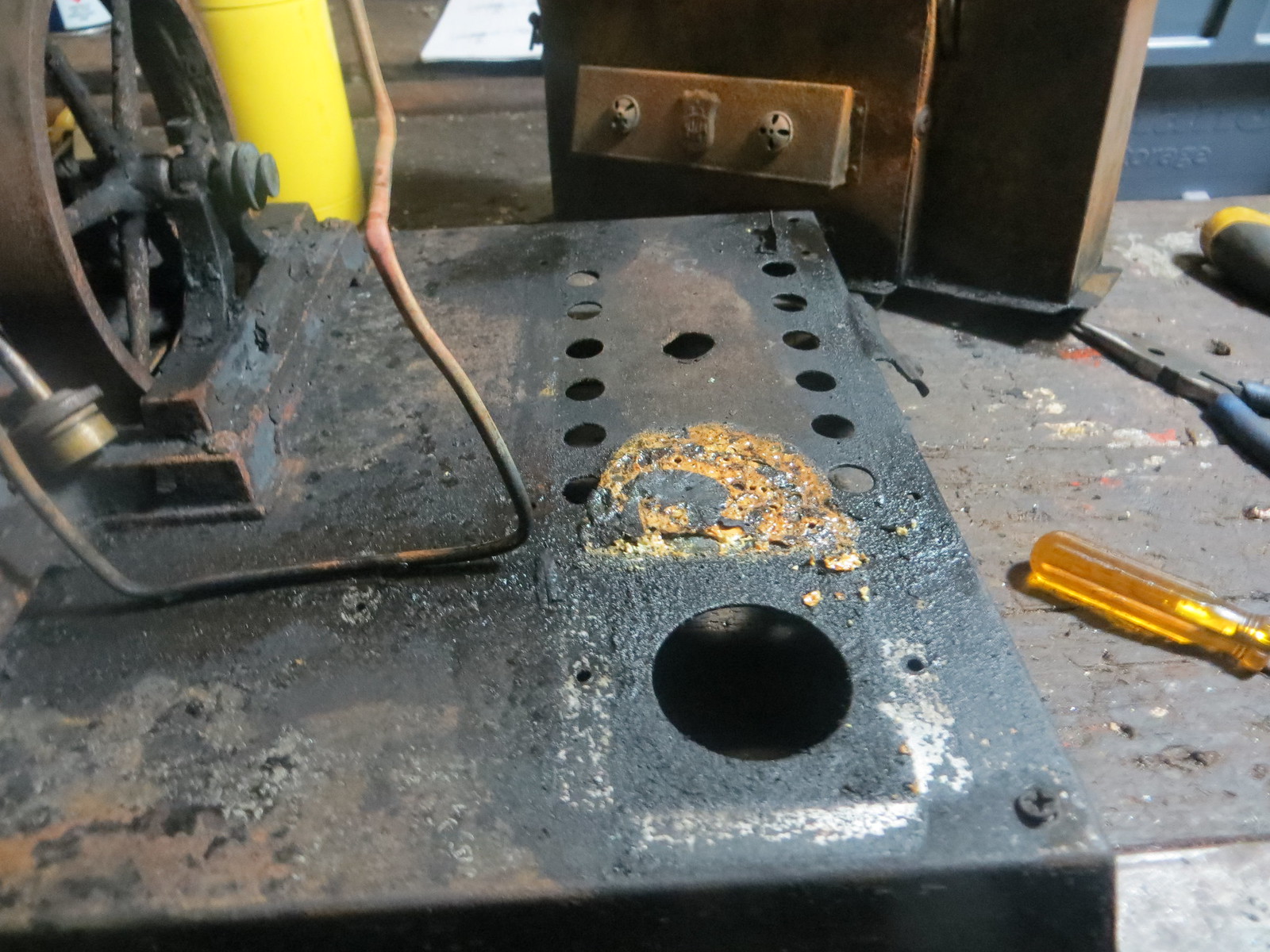
Boiler and firebox removed. The yellow-brown patch is some kind of plastic that melted in the fire.


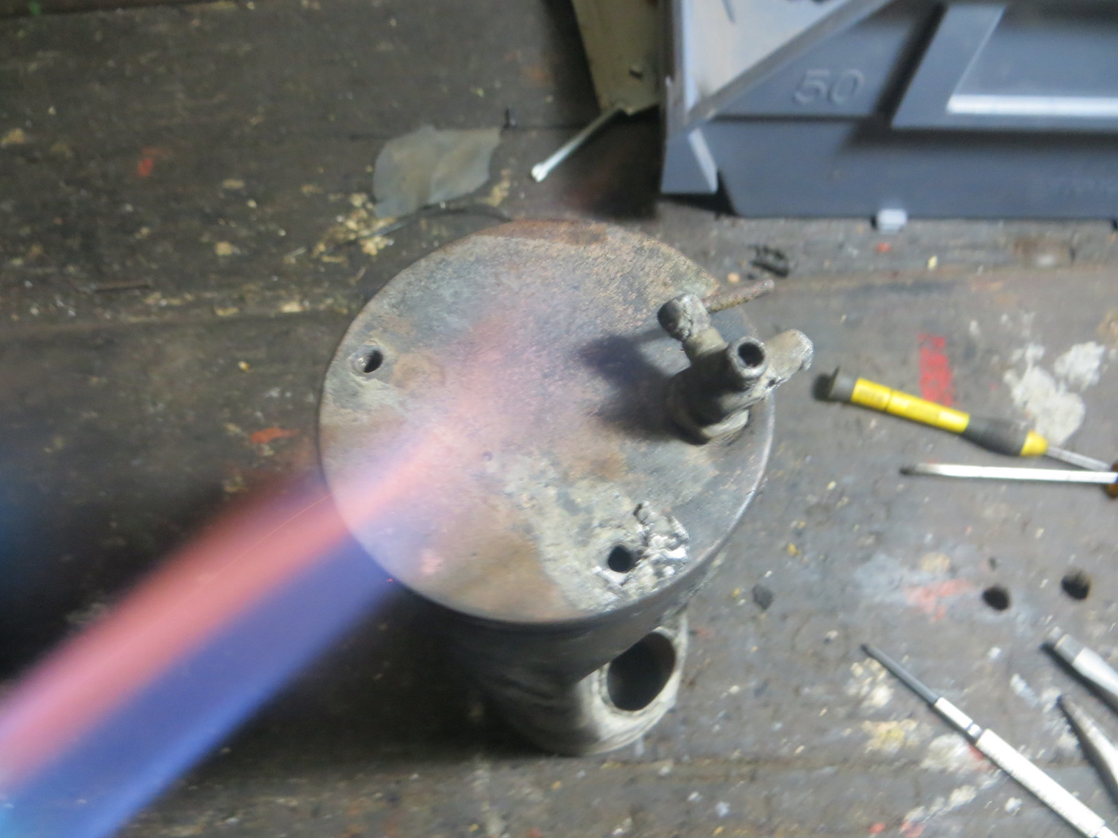
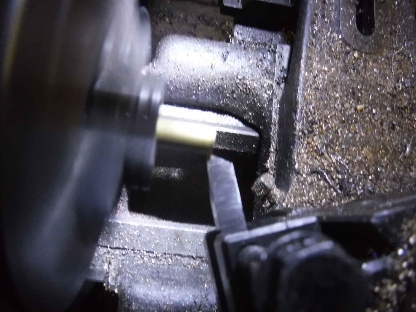
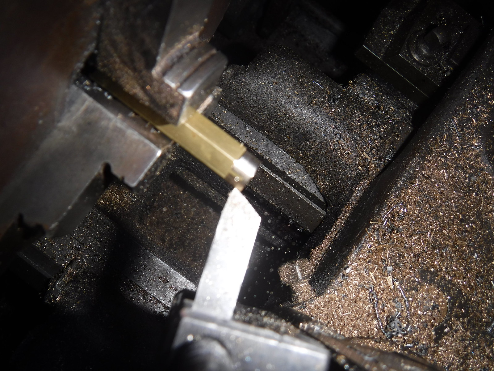
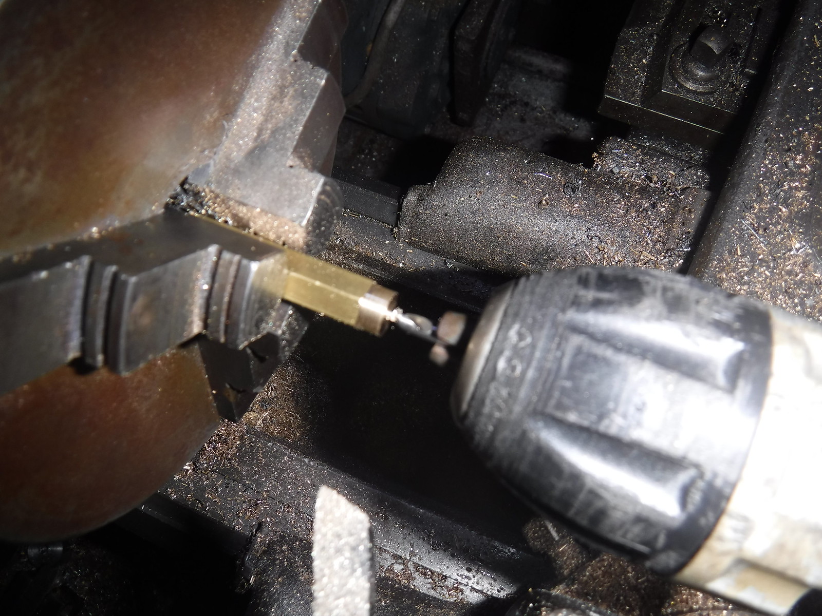
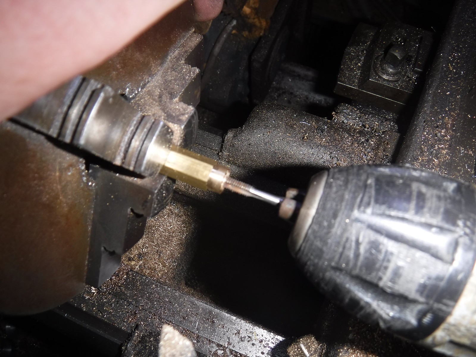
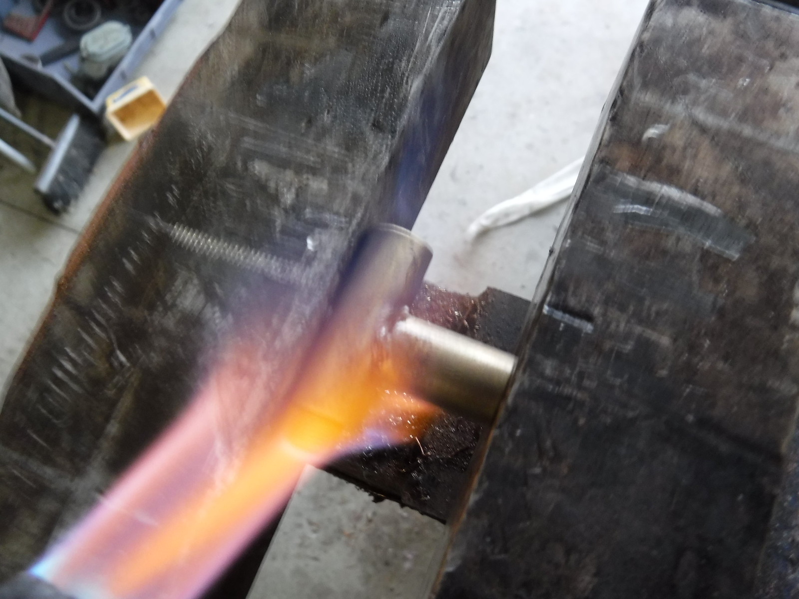
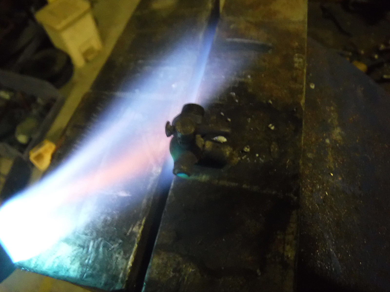
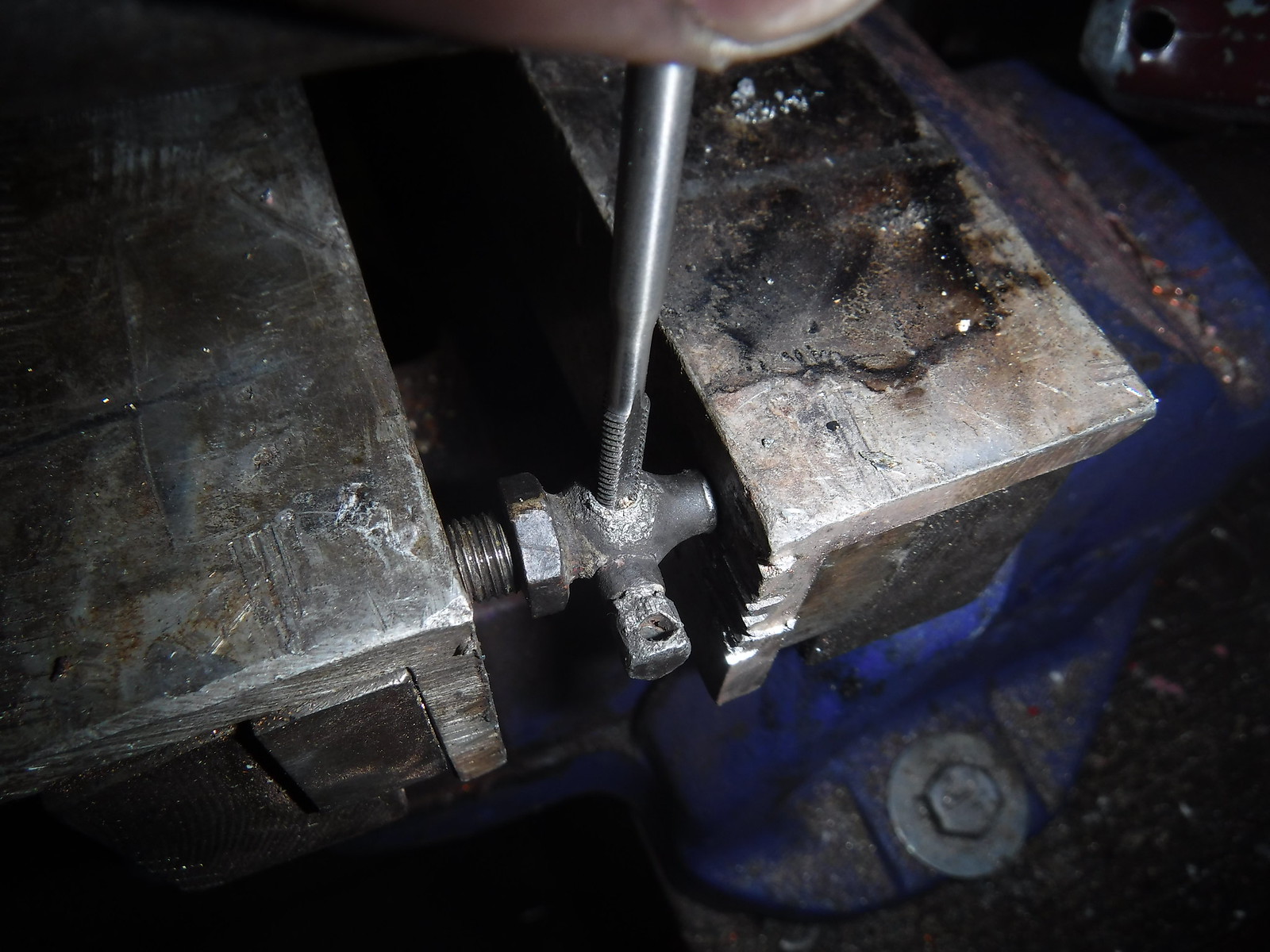
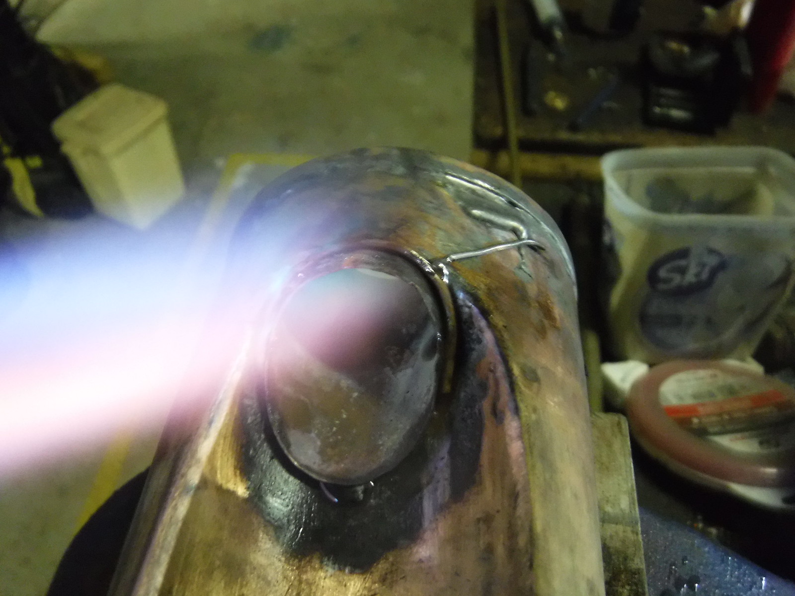
De-soldering the steam pipe from the engine.


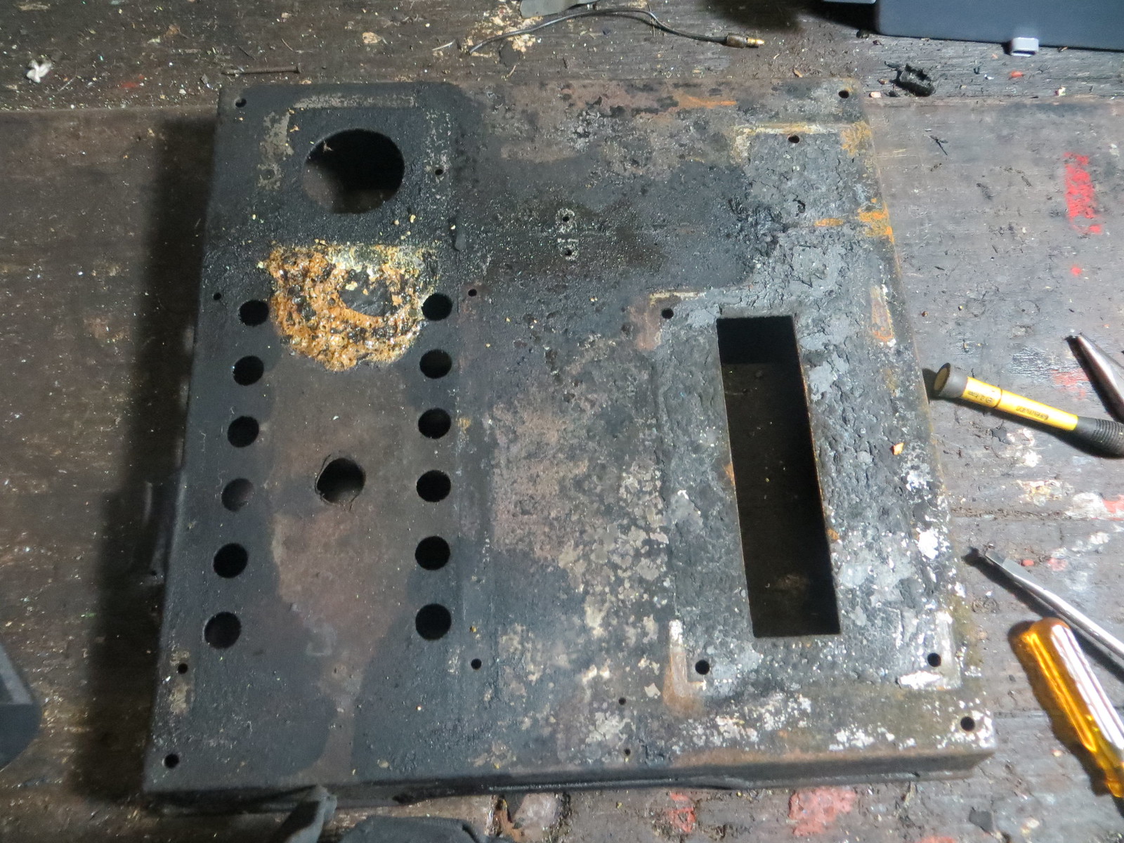
The base with everything removed. Not sure what to do about that ugly cut-out on the firebox side. Maybe I could try and solder a backing plate in to hold the cut piece in position? The corner braces were soldered in, so it is definitely doable in theory, though the fire could well have damaged the plating since tin melts somewhere around 250-300 degrees, similar to lead's melting point. However the plating may have survived in some areas, suggested by an apparent lack of rust beneath the scorched remains of the old paint.


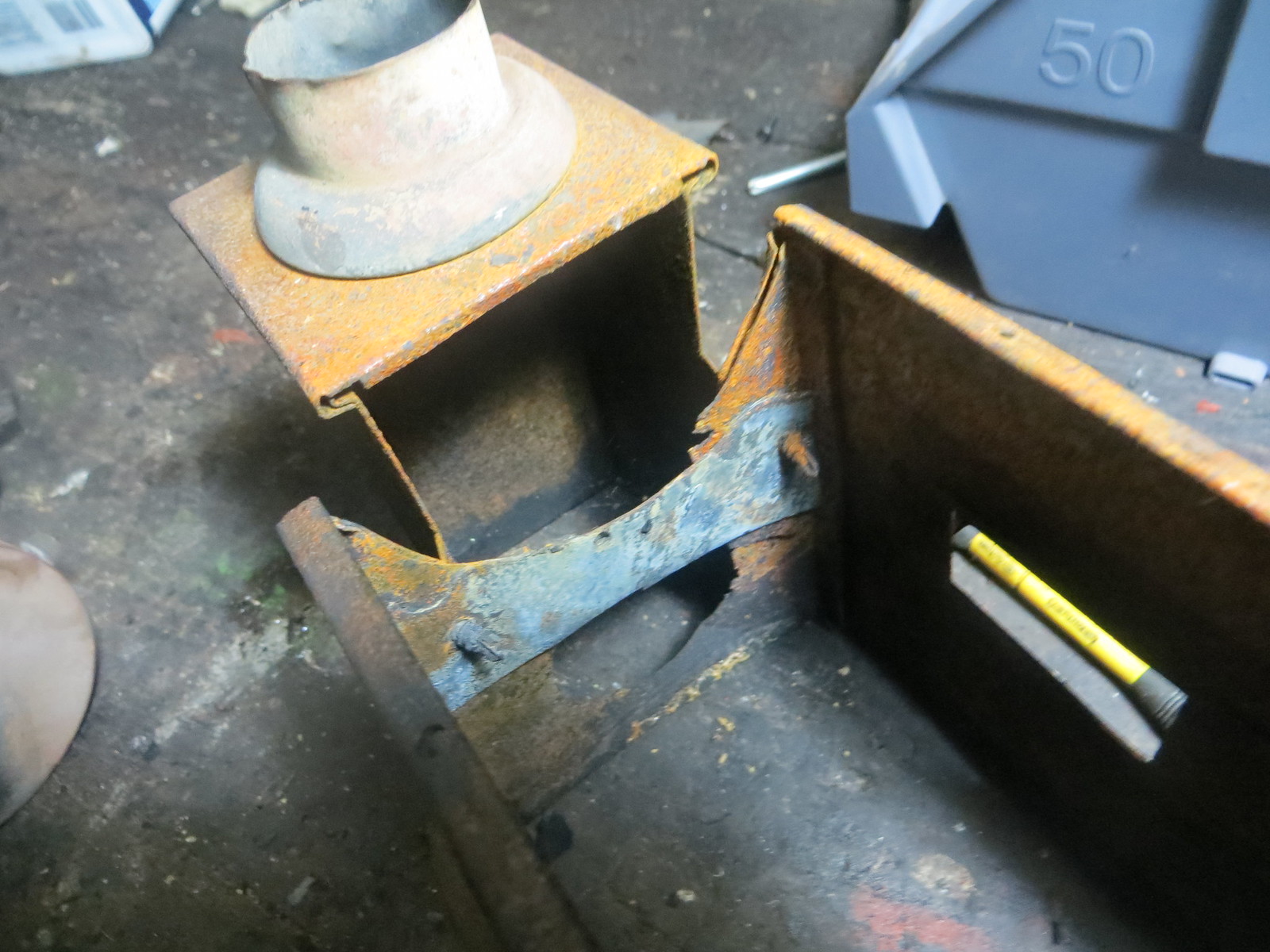
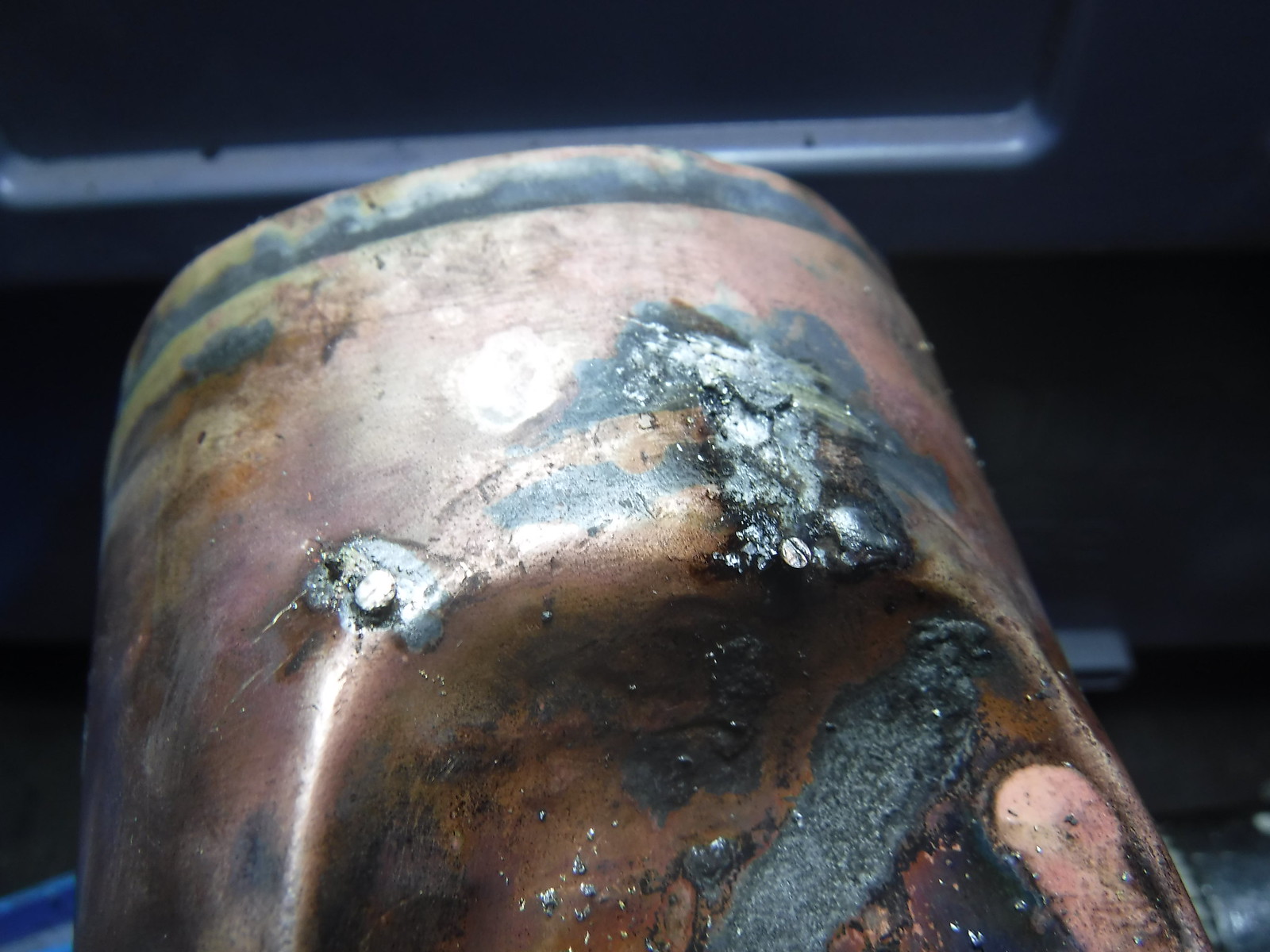
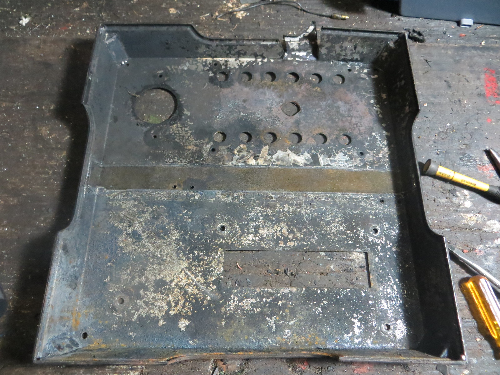
With the firebox removed, I discovered this hideous looking patch behind the chimney base held with tek screws (normally used for holding down corrugated iron roofing). I see some evidence of rust problems that predate the fire, which I'll bet is the reason it was patched. This is how NOT to patch up the firebox on your steam engine. I'll definitely be doing something about this bodge job.


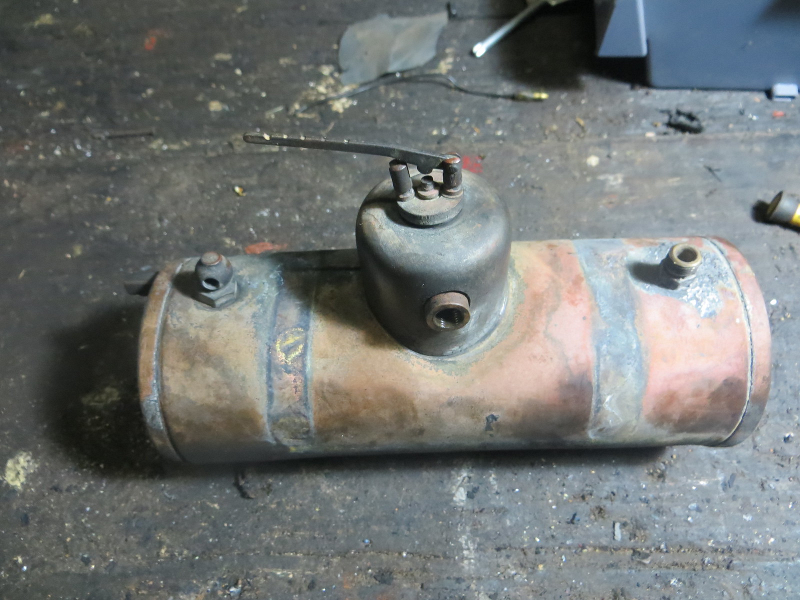
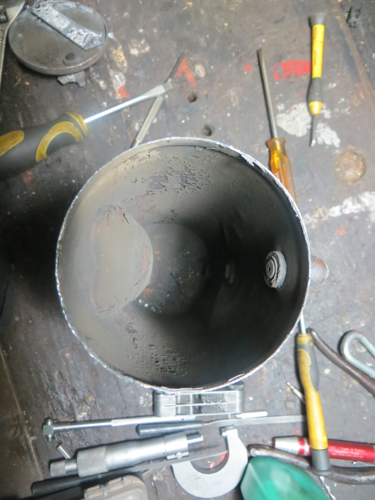
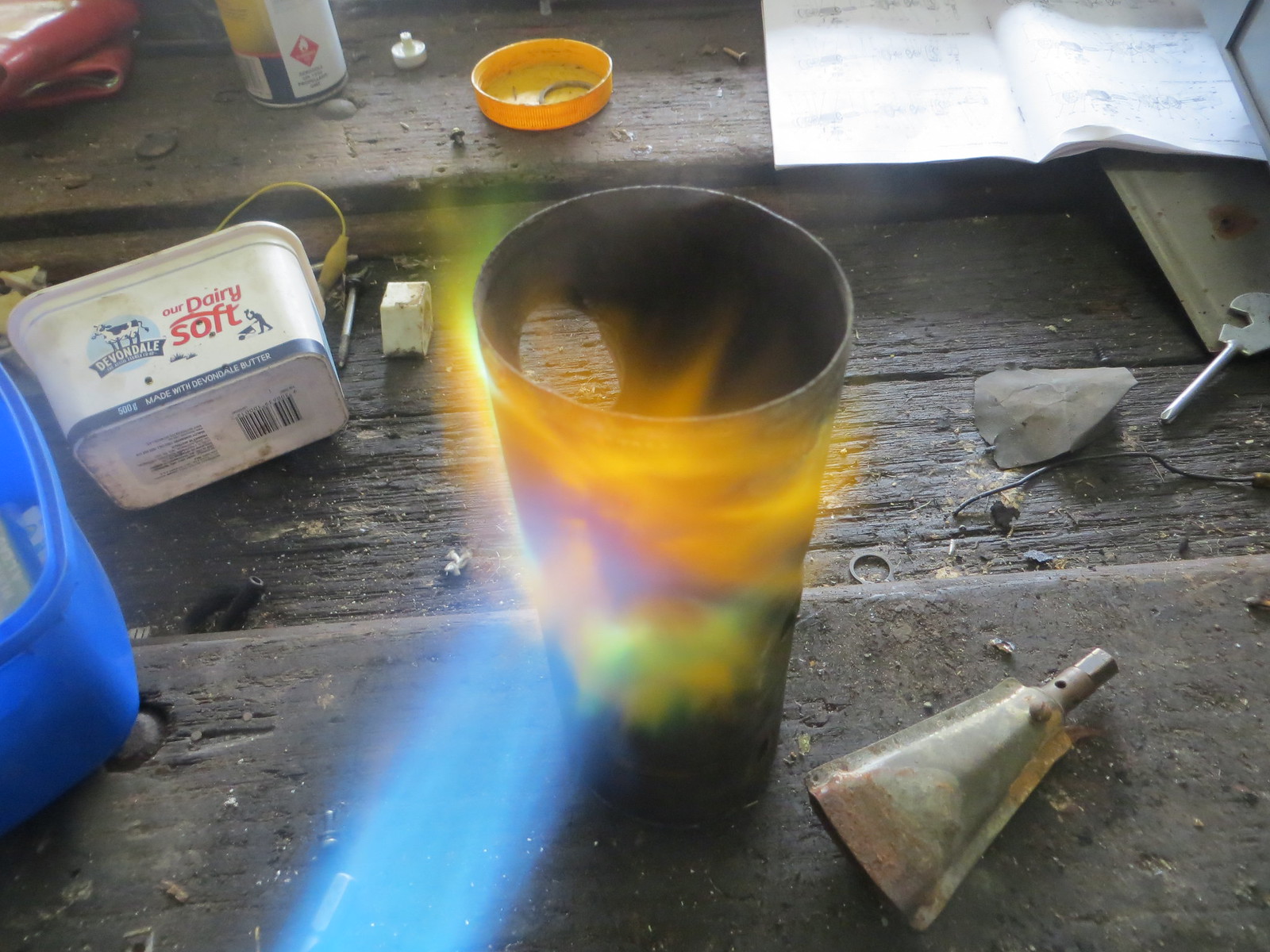
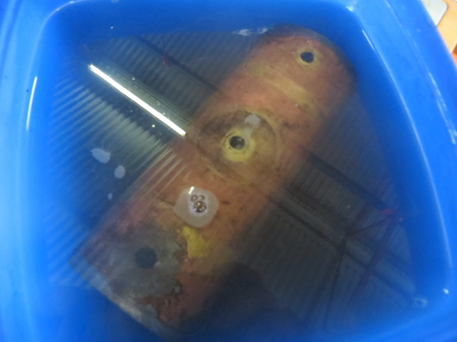
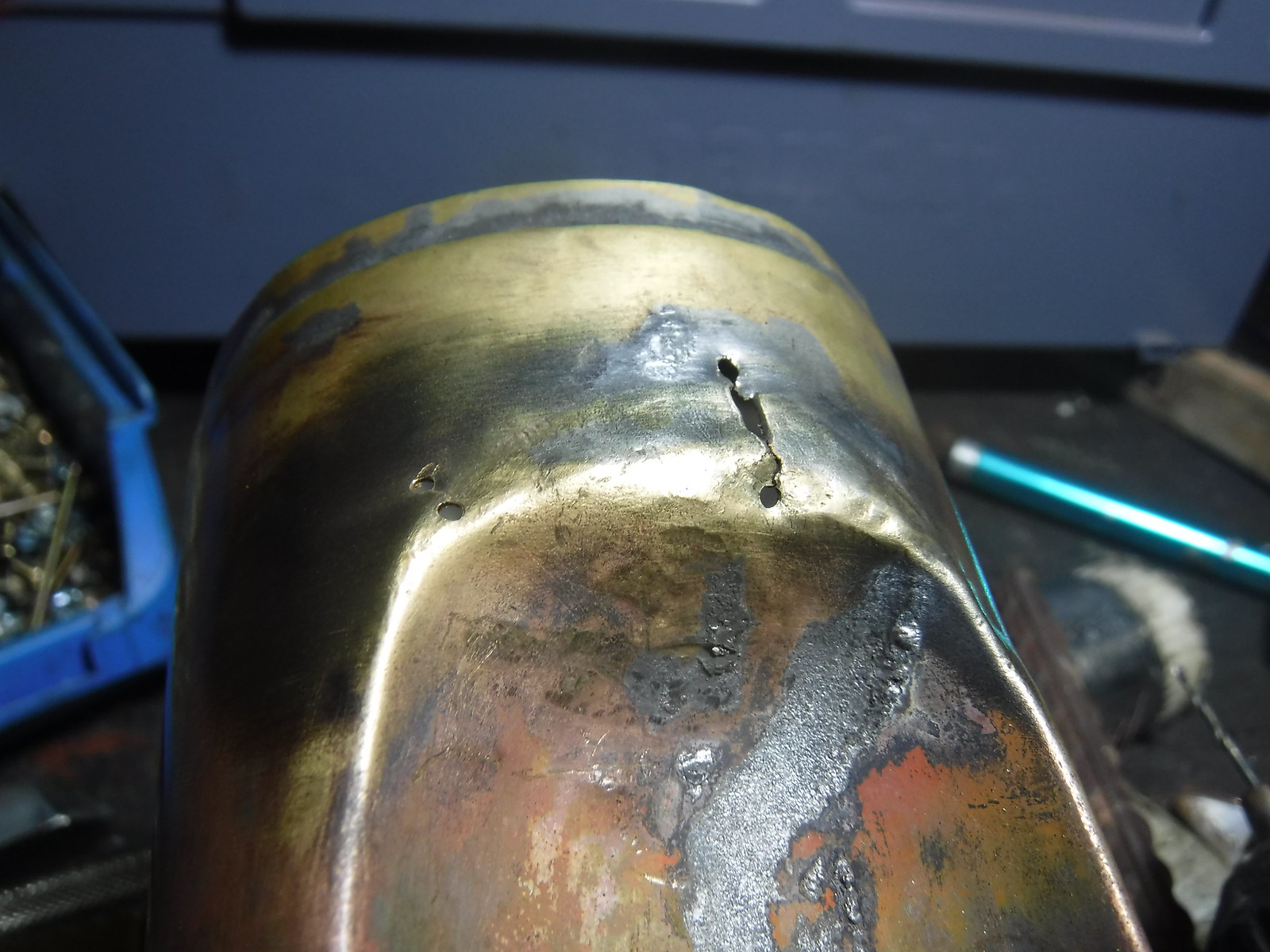
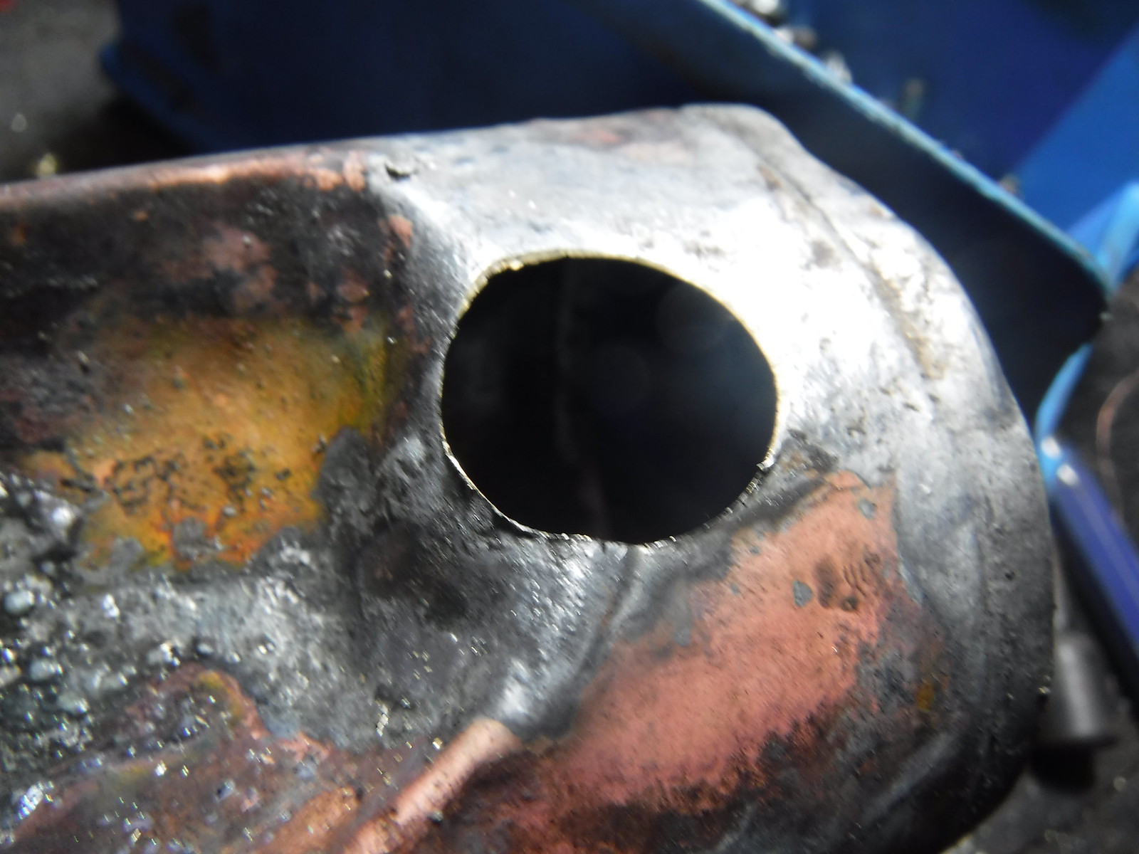
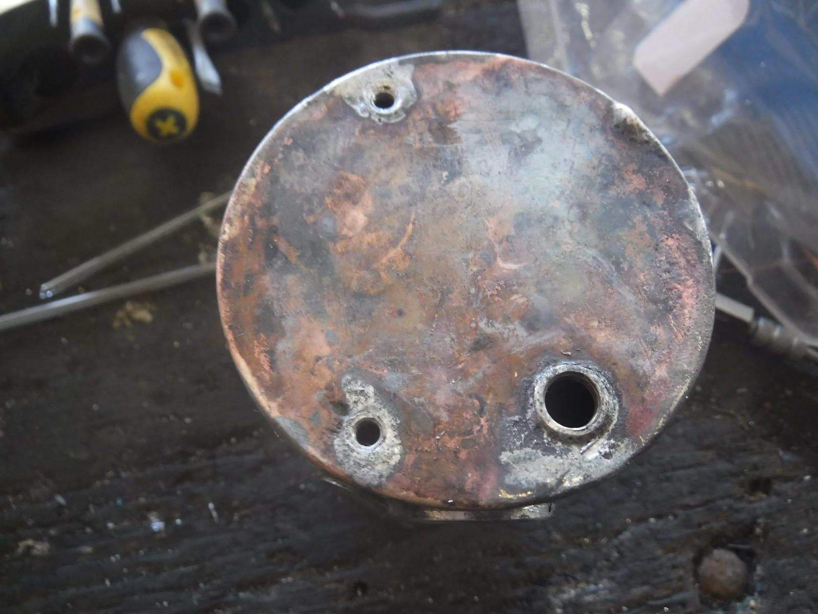
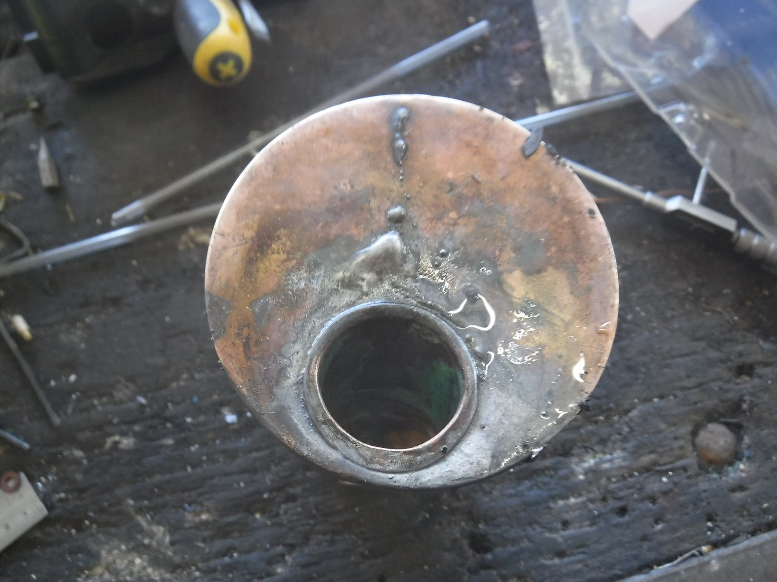
One feature which I believe (though I may well be wrong here) is unique to Marklin is the boiler. At first glance it looks like a regular pot boiler, until you look at it from underneath...


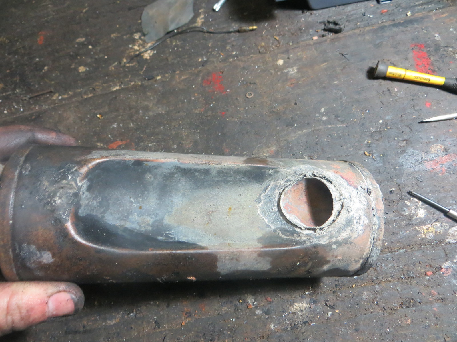
At which point you will realise it has a single short flue at the chimney end. Is this kind of boiler unique to Marklin, or were other manufacturers using it at some point? I believe Marklin did this to improve the steam-raising abilities of their larger boilers, as this design, unlike a pot boiler, has a draught through that flue.

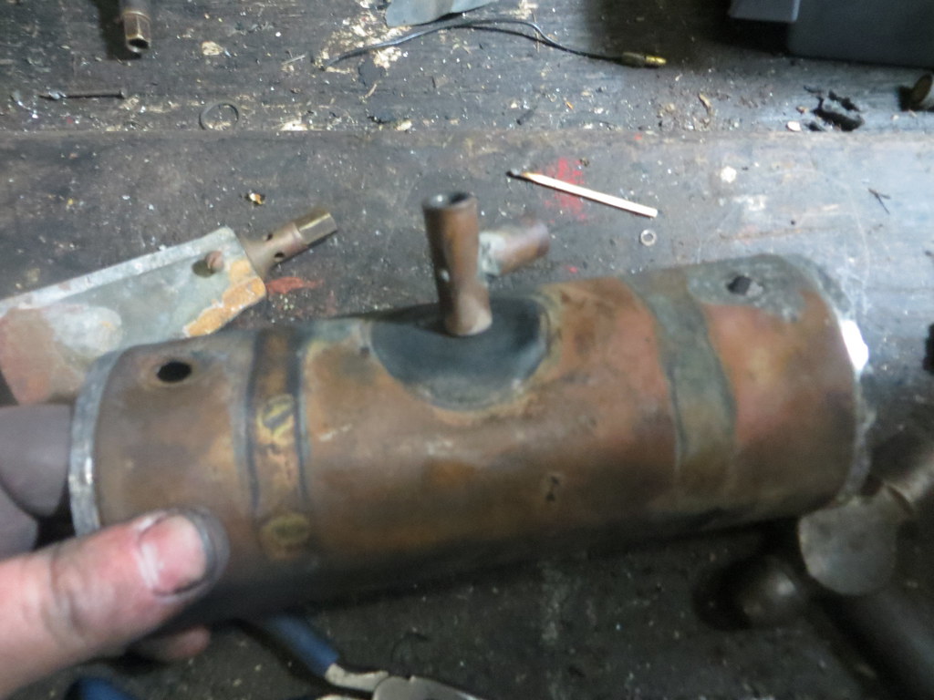
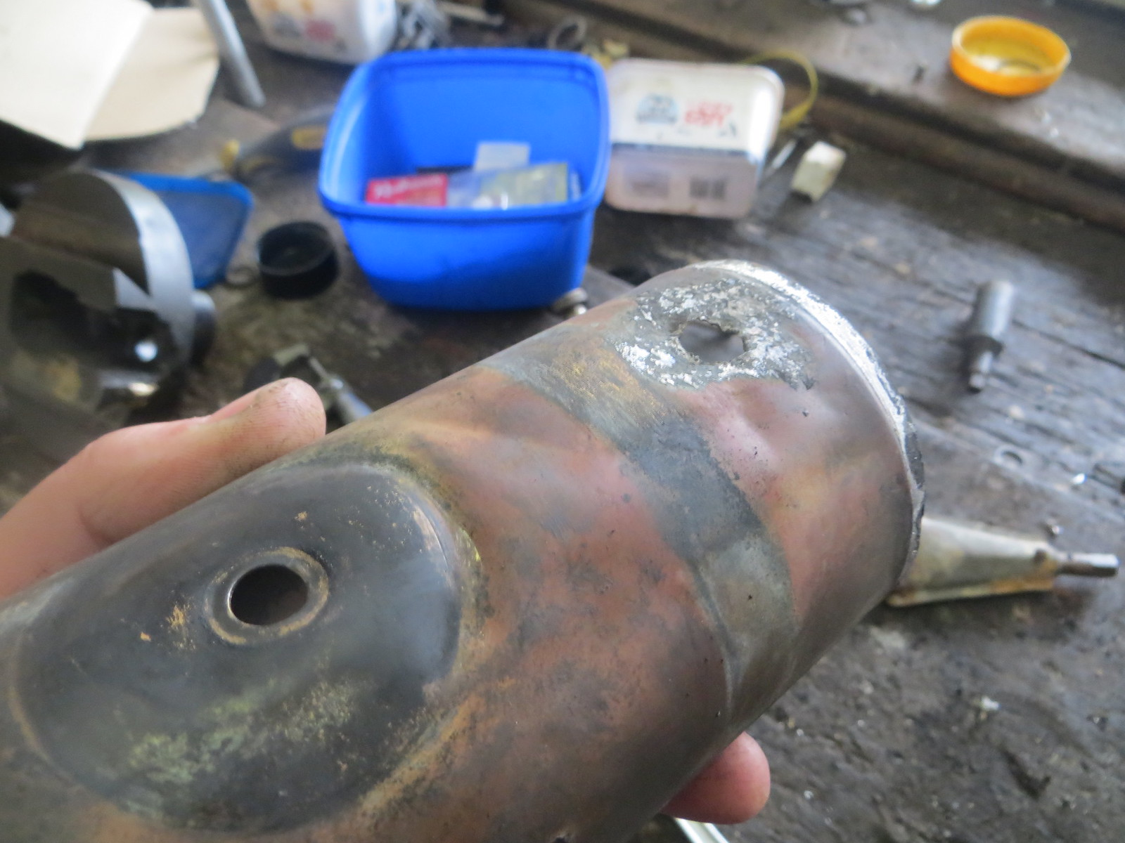
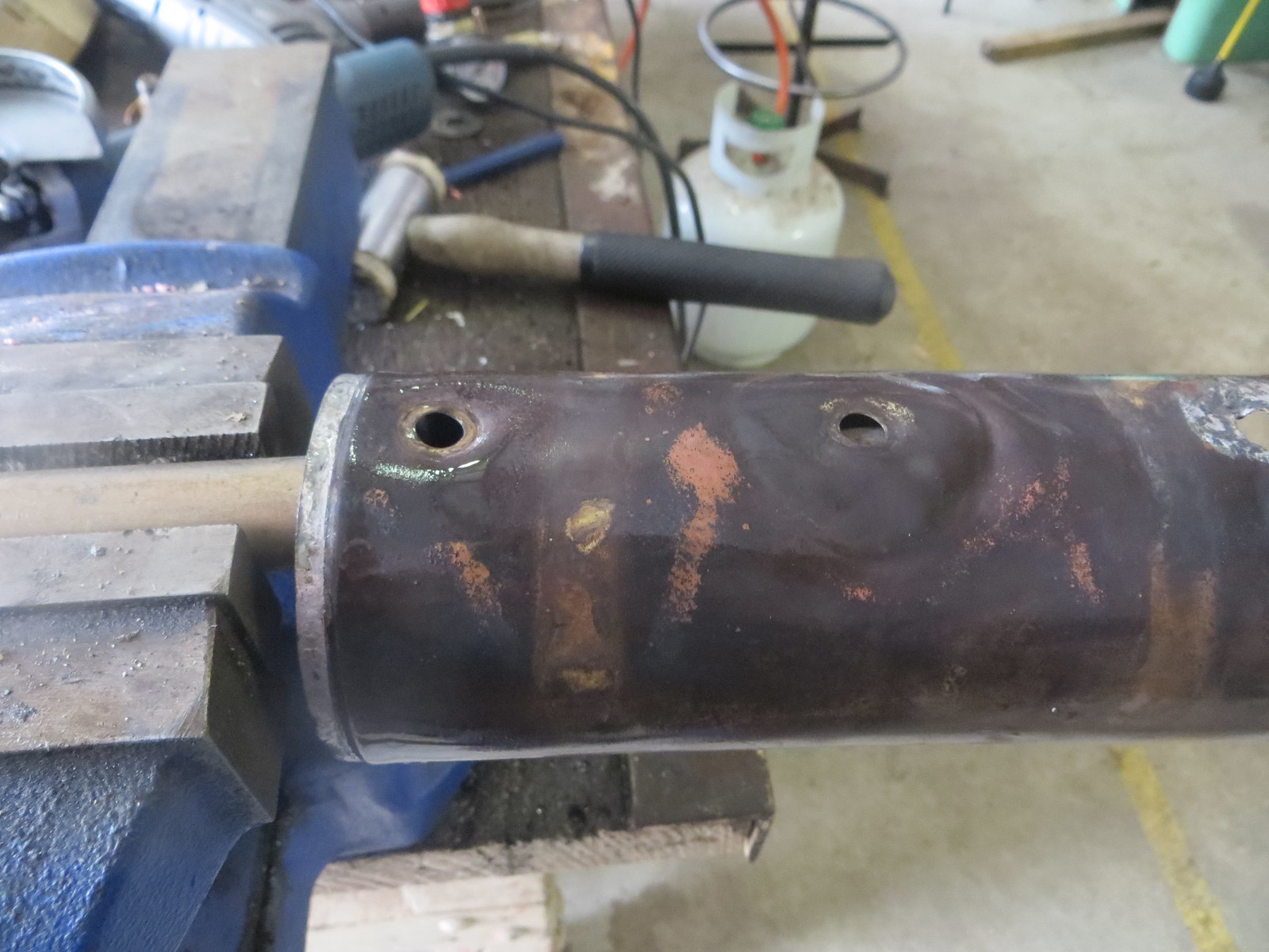
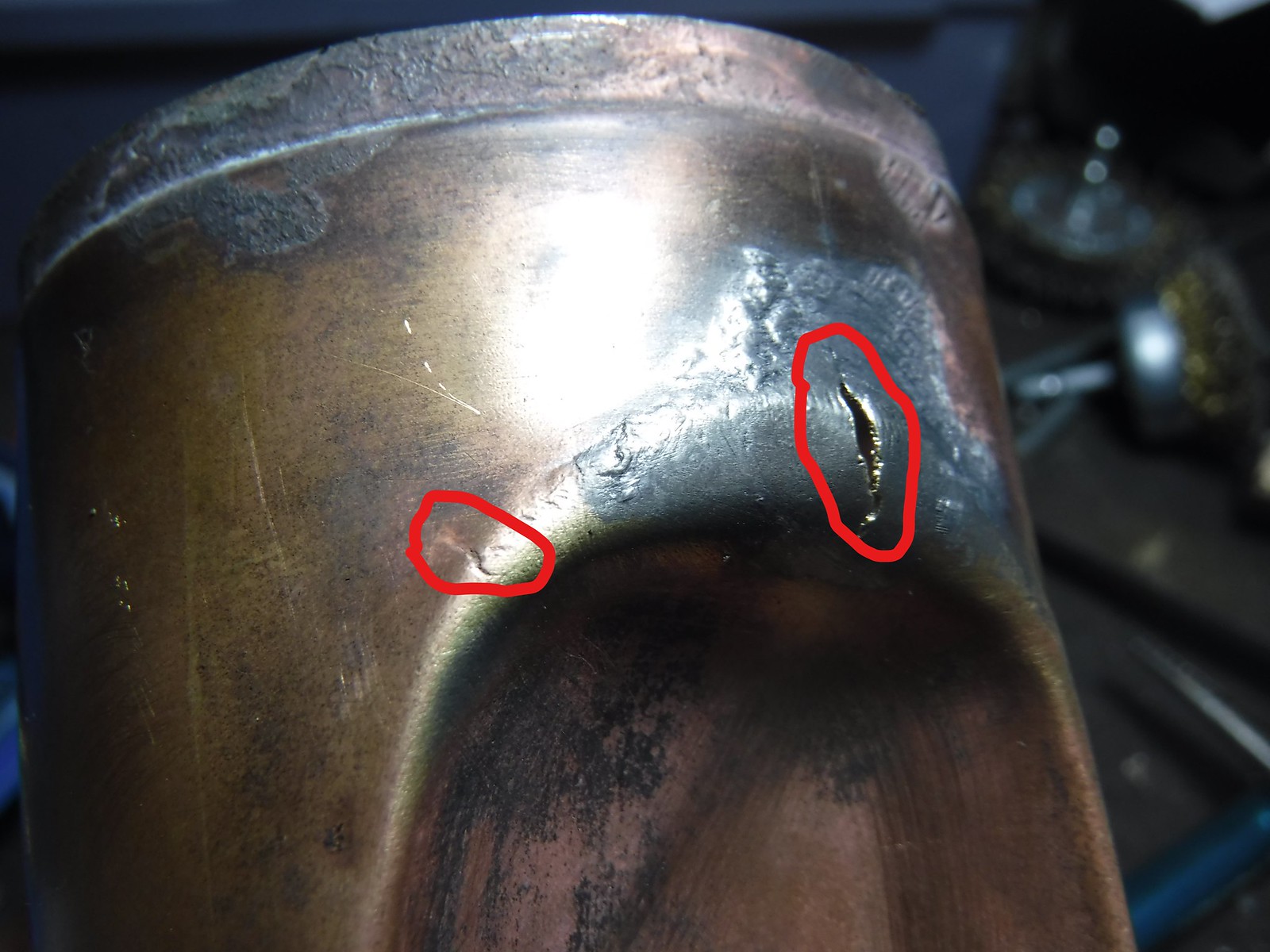
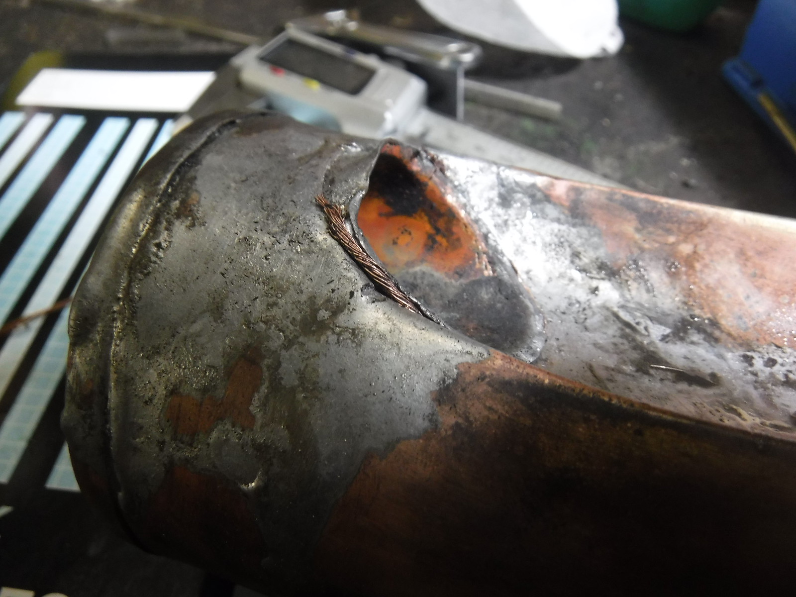
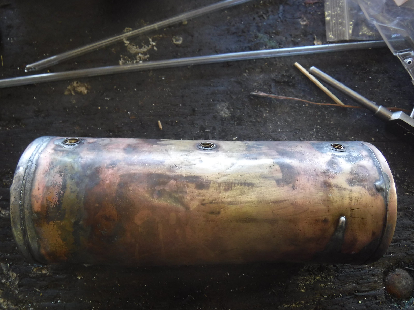
This boiler needs a fair bit of work, as the solder had melted off most of the bushings, and I also discovered a total of three cracks in the bottom; two right next to the flue and one directly opposite to it at the sight glass end. I believe the sharp bends in the boiler barrel are a weak spot, as these creases have a lot more strain on them than the rest of the barrel. However, I do have a solution to this problem, which I will elaborate on as work progresses.

That's about it for now. If anyone can provide information on how things are supposed to look on one of these engines, please let me know.
 
Been having a lot going on during the last few weeks, including getting a new camera as I dropped and broke my old one, but I've been making progress with this engine.

With everything stripped down, I decided to start repairing the boiler.


De-soldering one of the end caps


This could well have been the first time the inside of this boiler has seen the light of day in over a hundred years!


The boiler barrel with everything except the steam outlet manifold (which was hidden inside the dome) removed.

That particular part took quite a bit of getting out, as the fire melted the solder off all the threaded bushings, and the bushing for this fitting was a bit tricky to reach.


Here's the barrel after removing the aforementioned steam manifold. The hole at the chimney end (to the right in this picture) had a modern 1/8" BSP x 1/4" compression fitting soldered into it to provide an air line connection. I'm guessing the owner did this himself as he was running all his engines on air when at shows, partly as he was concerned about not being covered by public liability insurance if he ran anything on steam. I will be making and supplying a proper air adaptor for this purpose.

I am thinking about attempting to manufacture a replica Marklin whistle, as this engine would have originally had one where that air line connection was. I'll see if someone who owns a complete example can provide me with some measurements and detailed photos to help with this.


The barrel was then annealed and hammered over a piece of steel round bar to remove some dents.


It was then pickled overnight to prepare it for soldering.


Meanwhile I started making some new bushings. The old ones did not have a shoulder on them, so they would have been a pain to position for re-soldering, and one was missing, so it's just as easy to make a whole set of them. They will be made from bronze rather than brass, so they will be immune to de-zinc. So a piece of bronze was set up in my old Hercus lathe and faced.

42742129252_1f05bedbff_h.jpg


Machining the larger diameter.

42742140252_0e8553a6c0_h.jpg


Drilling out the stock to tapping size. Just in case you were wondering, yes, I did use a centre drill to start the hole.


Tapping, which was started using the lathe's slowest back gear until the tap managed to get a good "bite", at which point I stopped and backed off to clear the swarf, then continued turning the chuck by hand. The thread on these Marklin boiler fittings by the way is M8 x 0.8, which was a thread I had never even heard of until I started working on this engine, so that tap is homemade. I might do a tutorial on how to make your own taps for odd, obscure threads, as it can save you a lot of bother when repairing things like this.


A test fit of the steam manifold confirms that I got it right when I made the tap.


Turning the shoulder on the first bush.


Parting off.


And here we have the new bushings ready to be fitted.

To be continued as the image limit prevented me from posting everything at once.
 
Continuing from the last post..


The sight glass fittings had been soldered in place, one was plugged with solder, the other had a nail stuck in the top of it in some half-hearted attempt to stop it leaking. When I stripped the boiler down, I discovered why they had been soldered to the end cap; the threads were all loose and sloppy. To fix this on the bottom fitting, I started by screwing it to a threaded mandrel held in the lathe as it has a threaded hole on the back for a drain screw, so I could remove the old damaged thread. Threads on these fittings are nothing unusual, the thread that goes into the boiler, and that on the drain screw are the same as a standard M4 thread, and the threads for the nuts that hold the actual glass are M3.5 x 0.6. No problem as I already had taps and dies for both of those; they're just standard metric threads. This is what I have found on most parts of this engine except the boiler fittings; they all seem to be identical to modern ISO metric threads.


The fitting was then set up in the 4-jaw such that the hole in the middle was running true.


Facing the back side square


Drilling and tapping for a new threaded section (effectively just a hollow brass stud). I also ended up having to repair the threads for the sight glass nuts using much the same method.


Making the new threaded sections.


The fittings after being repaired. Notice there is only one nut in the photo, the other one was missing, so I went and made a new one, which I will cover next.

To be continued yet again...
 
On to making that sight glass nut.


A piece of 5/16" brass hex was set up in the lathe and faced.


Machining the round section


Drilling and tapping an M3.5 thread to suit the fittings


Opening the hole out to 6mm part way down to suit the glass.


Parting off.


Cleaning up and facing to length.


The finished nut on the left, with the old one on the right. Quite a good match, don't you think? At least I think so. I actually made a pair of them as the old nut was sloppy on the new thread, and on the glass, so I was concerned that it would leak badly.

Next I will cover the repairs made to the boiler itself.
 
Now for the boiler repairs, and a bit of work on a couple of the fittings.


The solder joint on the steam manifold was touched up a bit as it looked a bit weak, possibly due to some of the solder melting in the fire. In hindsight it seems quite amazing that this joint was still holding at all considering the engine had been in a trailer fire!


The boiler feed bypass valve was seized and plugged with solder, but a bit of heat with a torch fixed that.


Re-tapping for a new bypass tube connection which will be made later on.


Now to address the real pressing issue with this boiler. During the strip-down, I discovered four cracks in the boiler barrel, which I've highlighted in these photos to make them easier to see. Cracks like these in a boiler must be seen to as soon as they are found, as if left untreated, they could continue growing and eventually get so bad that the the whole boiler could fail explosively. This is a risk even when running the engine on air, as the boiler will still be under pressure regardless.

On engines like Mamods and Wilescos, I would be inclined to simply fit a new boiler. This engine is a different matter due to its age and relative rarity, so I will be doing repairs as I am trying to retain as many of the original parts as I feasibly can.


The new bushings were soldered in


The flue and the end cap for the chimney end were intact, so they were soldered back on.


A combination of brass rod and copper wire were used to reinforce the solder joint at the bottom end of the flue.


On the backhead end, the first attempt to patch the cracks involved using brass plates soldered inside the boiler, with small brass pins poked through the holes which were drilled at the ends of each crack to stop them spreading. This didn't work out too well, so a different method was used.


For the second attempt, an area around the crack was drilled out to accept a solid brass plug.


A plug was turned on the lathe to fill the hole.


Soldering in the plug


Soldering the backhead end cap to the barrel after all its bushings were soldered in. I made small bronze bushings for the sight glass fittings, while retaining the original brass plate that had tapped holes in it, which now serves to stiffen the end cap in order to better cope with being under pressure.


The mostly finished boiler awaiting cleaning, polishing and a pressure test.

That's about it for now. I have been pondering whether to get some of the parts nickel plated as they were originally. There is a local company that can do it for me, but that would cost at least $60, quite possibly a lot more depending on how much preparation and fine polishing they have to do. I'm also thinking about experimenting with doing it myself, but to do that I'll need to order some nickel for an anode and a suitable electrolyte off eBay, as that's the only place I can find them as yet.

What's your opinion? Do you think it would be worth the time and money spent just to recreate the nickel plating? Have any of you ever done it or had it done on one of your engines before?
 
I have nickel plated at home using a commercially available plating solution with no need of any anode material at all. It was simple to do - surface prep and clean, and either dunk in a tank or (as I did for some exhausts) brush the solution on with a charged brush. Results were good, though once I compared with a chromed finish it looked a bit yellowish in comparison to the 'blue' hue of chrome, so I then chrome plated over the top. In the picture below you can see a huge difference in the finishes though in the flesh it is not so apparent (unless they are side by side you might not notice much).
exhaust16.jpg
 
Still uncertain about the nickel plating, as I'd have to find where I can get some of that plating solution, but anyway, on with the job at hand.

With the boiler mostly done, I turned my attention to the engine itself. I discovered that many of the moving parts were badly worn from all those years of running, possibly with inadequate lubrication at times. Micrometer measurements showed that the old piston rod was a full 0.25mm undersize. The old piston seemed to still be within tolerance, but the bore was oversize by around 0.1mm. I decided that this meant a new piston rod and an oversized piston were needed for this engine to run properly. Fortunately, the valve and its valve chest were still within what I would consider reasonable tolerances, so I was able to leave those alone.


The hole in the rear cylinder cover was a bit out of round and, interestingly, a little undersized; so it was cleaned up with a reamer to bring it to exactly 5mm I.D.


A piece of brass was then centre drilled in preparation for making the new piston rod.


Turning down to size while the work is held in a collet to keep run-out to a minimum.


The rod was lapped with very fine emery to get a good fit in the cylinder cover.


Parting off.


Turning down for an M3.5 thread to suit the piston.


Machining a 20 degree taper which locates the piston on the rod and ensures that it remains concentric.


Threading the end with my homemade die holder.


A test fit with the old piston confirms that I got the taper angle right.


Turning and threading the other end of the rod with an M3 thread (no taper required) to suit the little clevis that holds the gudgeon pin.


The new piston rod on the right compared with the old one on the left.


Next was the new piston, but I needed a way to cut that 20 degree taper in the centre of it. I decided to make a tool for this which works like a countersinking bit.

I'll cover how I made this in another thread which will be something of a tutorial on how to make custom cutting tools for a job.
 
Back
Top