Making miniature ball joints

Home Model Engine Machinist Forum

Help Support Home Model Engine Machinist Forum:

This site may earn a commission from merchant affiliate links, including eBay, Amazon, and others.

GailInNM

Administrator
Staff member
Administrator
Global Moderator
Joined
Feb 17, 2008
Messages
2,326
Reaction score
440
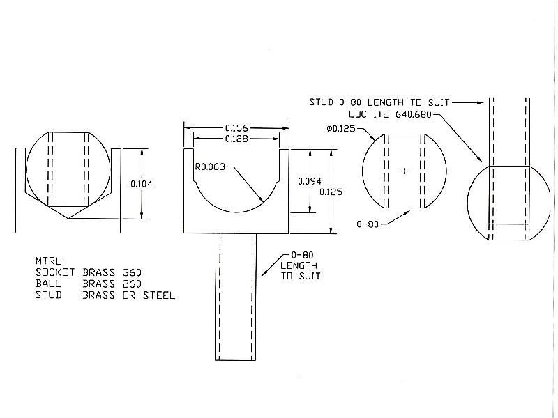
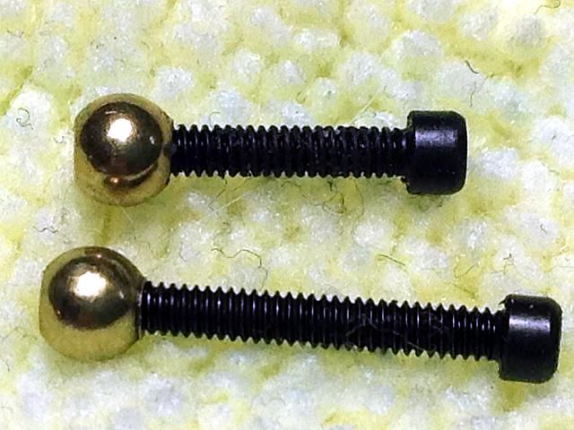
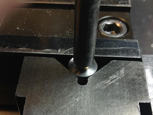
One of our members is currently building Elmer's #34, Cross Twin Engine. One of the few places that Elmer ever had a design flaw was in the valve linkage of this engine. The valve link connects two parts rotating through an substantual angle at 90 degrees to each other. With a pin at each end the link bar must bend if the pins are close fitting or if the holes are made oversize there is considerable play in the linkage at mid valve position. I did not find either method very acceptable so ball joints were made. I have since used them for several other linkages.

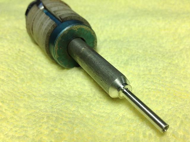
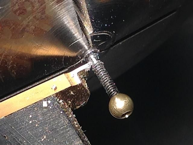
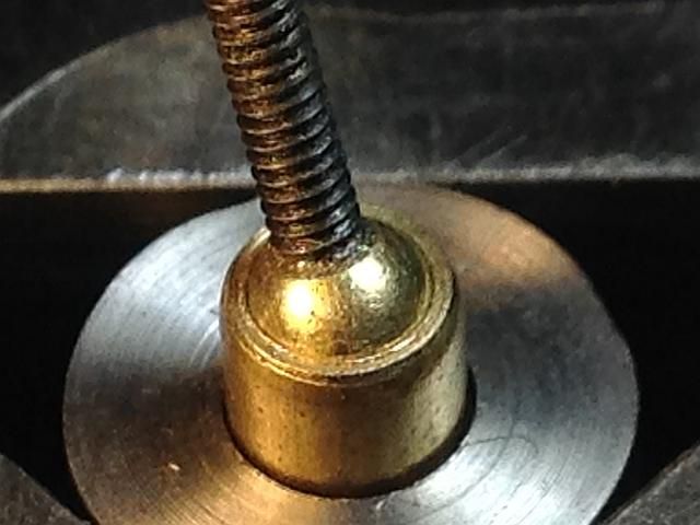
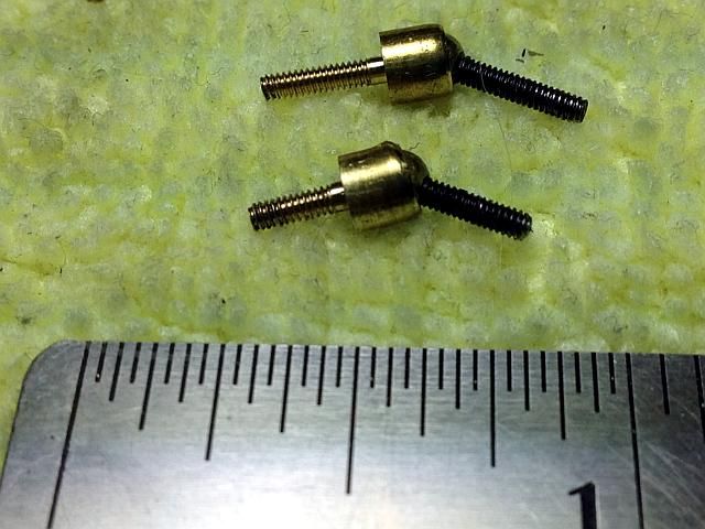
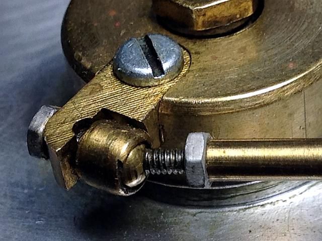
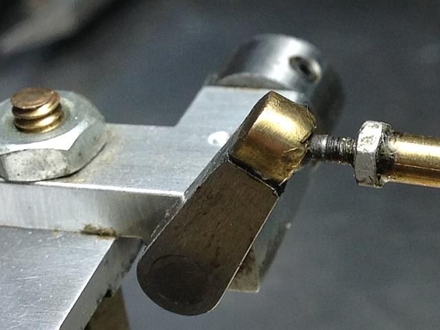
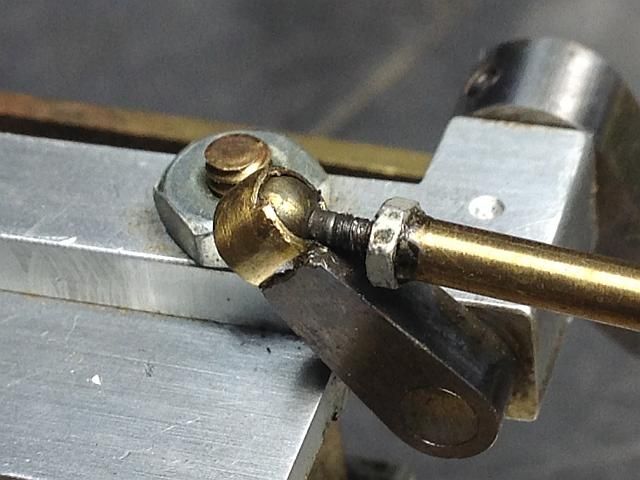
Here are photos of the Cross Twin Engine link ends. This engine was built over 20 years ago and my workmanship has improve some since then but you can see the problem. For size reference, the threaded sections are 0-80. In the first photo you can see the half hole remains of the original hole for the pin used in Elmer's linkage as built according to plan and then replaced.

BJ0001_zpsb6c8a70c.jpg


BJ0002_zpsedec8394.jpg


BJ0003_zps37dba2d7.jpg
 
Last edited:
The balls are 1/8 inch (0.125) diameter brass. They are available from most tooling suppliers but I get mine from Toolsupply on Ebay. They have been selling all kinds of ball on Ebay for many years. The 1/8 brass ball are currently US$ 6.00 per 100 with free shipping if you buy from the Ebay listing. If you buy from thier ebay store they charge an extra US$2.00 for shipping. Other places like MSC and McMaster Carr have them for US$ 7 to 8 plus shipping. I have been buying from tool supply for many years and they have always given me good service.
http://www.ebay.com/itm/380792857744?ssPageName=STRK:MEWAX:IT&_trksid=p3984.m1423.l2649

Lets start building with the drawings.

First off the parts of the ball joint. Two variations of the socket are shown on the left. One for using a drill bit to form the socket and one for using a ball end mill. Your choice. Both seem to work equally well. If you use the drill bit method, the drawing dimension are for a 118 degree point drill bit. Do not use a 135 degree point drill bit as the stud hole in the ball will be riding on the bearig surface and cause some binding.

BJDWG0001_zpsda30f732.jpg

The second drawing is the tooling to stake the ball in place in the socket. Both parts are made from steel. Any steel. I use 12L14 and it is quite adequate.
Gail in NM
BJDWG0002_zps15b031a4.jpg
 
Lets start building.
The photos show all the lathe work done in 5C collets in the lathe, but I did the originals in a drill chuck mounted on an arbor and chucked in the standard lathe chuck.

Although not essential, a stop to locate the ball makes life a lot easier. Here is the stop that I used in the 5C collet.
BJ0004_zps7694be39.jpg


The tip of the stop is 0.120 inch diameter to allow clamping on the ball. The hole is 0.078 to allow clearance for the tap drill and tap when machining and should be about 3/8 deep.

If you use a drill chuck that does not have a through hole, a stop of 0.120 diameter with a 0.078 hole can be inserted in it to make a stop. With a drill chuck be careful not to tighten it too much as the jaws can deform the ball. This is not a problem when using a collet.
Gail in NM
 
Machining the ball.
All that needs to be done to the ball is drill and tap it.
The ball is center drilled and then drilled with a tap size drill. For 0-80 threads use a #55 drill if using a cutting tap. I use thread forming taps so I drilled #54.
BJ0005_zpsefbf45a9.jpg


And then tapped.

BJ0006_zpsc76eb1e4.jpg


After tapping, and before removing the ball, polish off any burrs on the ball with some abrasive paper or cloth. I uses 320 grit. If you screw a 0-80 screw into the ball to remove it, then the other side can be rubbed on the abrasive paper using the screw as a handle. Just rub enough to remove the burr as we don't want to change the ball geometry.
Gail in NM
 
On to the socket.
Start with some 5/32 brass 360 rod. Face off the end and center drill it.
BJ0007_zpsa664330d.jpg


Then either drill to depth as shown on left illustration on the first drawing or to a depth where the flute provided a full diameter for a depth of about 0.032 for extra clearance if using an 1/8 ball end mill to form the pocket. A standard ball end mill will cut slightly undersize as they are ground out of 0.125 stock and the ball is slightly undersize. If you let the end mill "idle" for a few seconds at the bottom of the cut it will probably come up to size as the tailstock will probably not be exactly on center line or from tailstock chuck runout. Or you can put a little side pressure on the tailstock chuck but this will probably not be necessary.

To set the depth of either the drill or ball end mill, use a feeler gauge to touch off the tool. I use a 6 inch machinist rule that I know to be 0.025 thick. Zero the tailstock dial and drill to drawing depth plus the thickness of the feeler.

BJ0008_zps9ce5dbfb.jpg

Extend the stock and cut for the length of the desired mounting stud plus the 0.125 length of the socket. Reverse the part and turn down to 0.060 diameter for the stud length. Using a tailstock die holder, thread the stud 0-80. Sorry but no photos of these operations.
Gail in NM
 
Back to the balls.
In the following photos I should have put a nut on the screws that I used to make the studs. Then after cutting off the heads the nut will clean up the burrs from cutting off. I normally do but forgot this time. Case of do as I say and not as I do.

I made the stud from 0-80 socket head cap screws. I used them as it is easy to chuck on the head to cut them off.

Screw a nut on the bolt all the way up to the head.Clean the ball and screw to remove any oils. Then use a SMALL amount of high strength Loctite, such as 640 or 680, screw the screw into the ball about 3/32 (0.09) of an inch.
BJ0009_zps2a7ec21b.jpg

After the Loctite sets up, clean the assembly up with solvent to remove and excess Loctite.
Gail in NM
 
Thanks Chuck. I had to run off for a while but lnow I see if I can get this finished up.

The ball assembly is chucked up by the head of the stud bolt and the head cut off. Then the cutoff end is cleaned up with a file,l grinder or deburring wheel and the nut is remove to reform the end. You may need to run a 0-80 die over the cut end to finish up the end.

In the photo you can see that I did not smooth off the end of the ball like I told you to do earlier. No problem as the stud makes a nice handle.
Gail in NM

BJ0010_zps5a5d9e92.jpg
 
Here is the business end of the anvil and punch used for staking. They are detailed in the second drawing. Any grade of steel works fine for these. It is convenient to make the anvil length the same as the jaw height of the vice you are going to use it in.
BJ0011_zps5f8b17e4.jpg


The anvil is held with a vee block in vice. I use my milling vice. The bottom of the anvil rests on the bottom of the vice jaw slide. Here the anvil is in place with a joint socket in place with the punch next to it. Notice the gap between the edge of the socket and the ball. This will be formed around the ball with the punch.
Before putting the ball assembly in place, a small drop of oil is put into the socket. About any light oil is fine. 10 or 20 weight or 3 in 1 all will work fine.
BJ0012_zpsf213936a.jpg

Gail in NM
 
Last edited:
The punch is slid over the stud and struck with a small hammer to form the socket around the ball. I use a 4 ounce ball peen hammer. You can remove the punch and check the assembly. How hard is hard in words. I strike the punch with about 3 or 4 firm blows. When inspecting, the ball should have some drag but still be able to be moved. It's not hard to get this type of fit as the socket forms around the ball and the spring back of the metal in the socket eases the pressure.
BJ0013_zps747e4b55.jpg


After staking the socket it looks like this. Notice that the gap around the ball that was there in a previous photo is now gone.
BJ0014_zps5ee1557e.jpg

Gail in NM
 
The ball joint is too stiff to use as is. Chuck the socket in the lathe (or drill) and running the lathe at about 500 or 1000 rpm hold the stud of the ball. Work it back and forth to the extremes of its angular travel and the ball and socket will polish each other up to a nice working fit. Thirty seconds or so is all it takes.

And you are done. Here is the finished unit ready to use. Thanks for following along.
Gail in NM
BJ0015_zpsedf86e2b.jpg
 
Last edited:
This is something that will come in really handy for me some day. Thank you Gail. Very well done.

Ron
 
A very informative post. Thanks for sharing.
 
That is excellent! Just in time for my build. Thanks for mentioning Elmer's "miss" and for talking the time to present a great solution. Balls are ordered.
 

Latest posts

Back
Top