Making Eccentric Clamps

Home Model Engine Machinist Forum

Help Support Home Model Engine Machinist Forum:

This site may earn a commission from merchant affiliate links, including eBay, Amazon, and others.

shred

Well-Known Member
Joined
Jul 19, 2007
Messages
1,949
Reaction score
7
With the arrival of a new tooling plate for my mill, I decided it was finally time to make some low-profile eccentric clamps. These are taken from the Mitee-Bite design (patented, but that's ok for personal use), but with some variations I wanted to try. Also check out Rick Sparber's great article on the same topic at: http://rick.sparber.org/Articles/tc.pdf

The tooling plate is tapped 10-32 (btw, I think next time I'll go for 1/4-20) and poking around, it looked like .040" was a reasonable throw value for a 10-32 size clamp. Firing up Marv's ECCENT program, told me I needed about a .030" shim to get a .020" offset out of my 3-jaw.

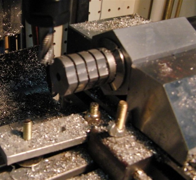
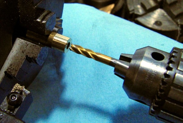
Scrounging around the scrap box came up with a scrapped small sterling fan blade of 1/32" brass (close enough) and a chunk of 1" 12L14 steel rod. I chucked up the rod with the shim in place and drilled and tapped a loose 10-32, creating the offset hole (I skipped the set-screw thing Rick did and preferred to have the screw all the way threaded into the block before turning the head-- 10-32s can bend too easily)

EccSm1.sized.jpg
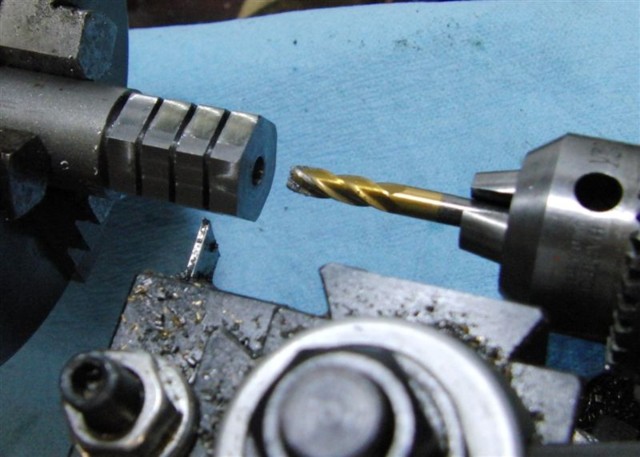
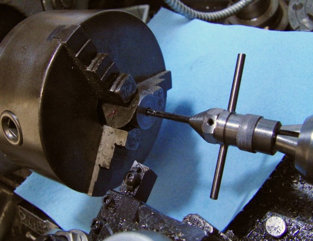
(also note the Marv-style tap holder)

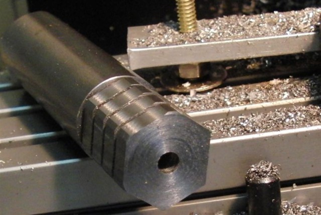
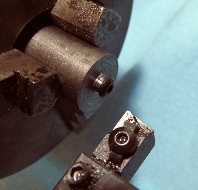
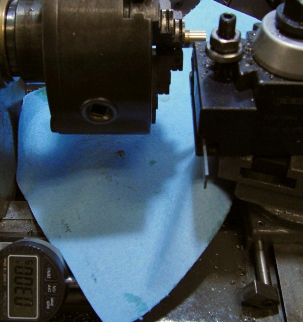
Then I removed the shim and screwed a 10-32 button-head in as far as it would go and turned it down to .250" diameter (actually after the first one I made the little boss to screw the screws to make it easier to cut them all the way)

EccSm5.sized.jpg
EccSm4.sized.jpg


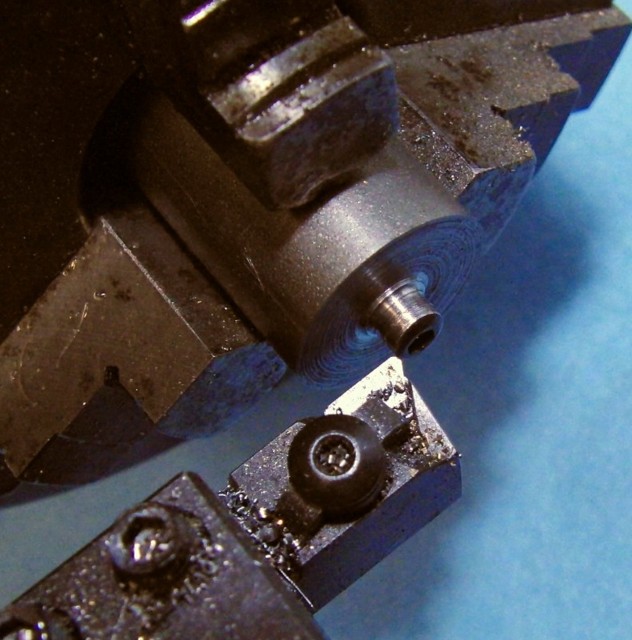
With the lathe set up like that I made a batch more offset button-head screws.

Then I chucked up some 1/2" brass rod (hex would be better, but the cupboard was bare of that-- see below), drilled it out with a #2 drill (you need a large clearance hole for the offset screws-- I just kept trying larger and larger drills..)

EccSm7.sized.jpg


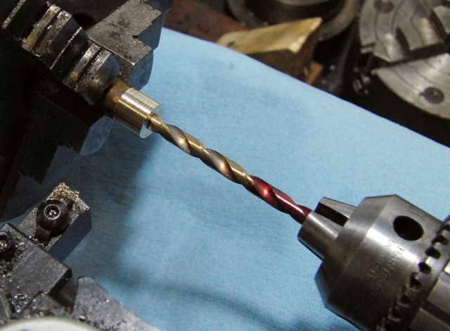
Then ran a 1/4" end-mill in .125" to create a flat-bottomed hole for the bolt heads (not the ideal solution, but works in this case)

EccSm8.sized.jpg


and parted off to leave a .250" tall cup washer. Easy to make a bunch quickly.

EccSm9.sized.jpg


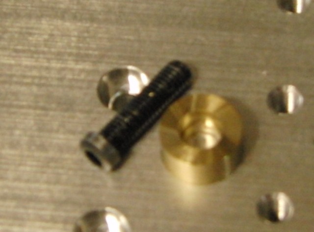
Here's a fuzzy shot of the bolt and washer pair:
EccSm11.sized.jpg


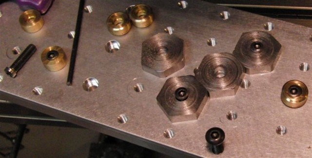
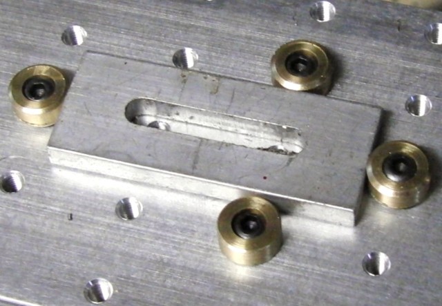
Here they are in use-- the trick is to run the screw down to the table, then back it off up to a full turn to the most-open position, then insert the part to be clamped and tighten the screws to hold it. Normally you'd probably want to use a fixed-jaw block on one or two sides of the workpiece or you could go nuts indexing it in.

EccSm3.sized.jpg


What's next? I want to make some hex washers wherein the distance from each side to the center increases by the throw of the eccentric, so as to create the most possible range from each set.. hmm.. maybe time to poke around Marv's site agan.. he might already have a cutting program for that... ;)


I like the idea Shred... I would like to see the tooling plate too please... I just want to know what it looks like in 'real life' ;D

I am going to have to look more at Marv's site too... I never thought of such a way to make a small eccentric!

What do you use or have planned use of this for? I am just intrigued as to a new type of work holding (new to me that is!)


Thank you.


Ralph.
 
What's next? I want to make some hex washers wherein the distance from each side to the center increases by the throw of the eccentric, so as to create the most possible range from each set.. hmm.. maybe time to poke around Marv's site agan.. he might already have a cutting program for that... Wink

I can't visualize what you're talking about. Draw me a sketch and I'll see what I can do.
 
mklotz said:
I can't visualize what you're talking about. Draw me a sketch and I'll see what I can do.
Imagine an irregular hexagon with a hole in the middle somewhere. The distance from the center of each flat to the center varies-- from say 0.23 to 0.43 in steps of 0.04--

Here's a sketch with alternating distances.. after I drew it, it struck me that this would be something of a nuisance to use, so maybe an increasing spiral is the way to go for usability.

Anyway, it seemed that the quick way to whack these out would be to mill some rod into this irregular hex and then whack off short lengths of it. Probably with an indexer or vertical RT-- chuck up some round stock, mill a flat at the lowest height, rotate the indexer 60', mill the next highest flat, and so on. Drill the center either before milling or hold the end of the round to keep everything else in place. Making one from the smallest possible diameter of round stock is left as an exercise for the reader ;) hmmm I wonder if the center hole were placed with enough cleverness that regular hex stock could be used... have to contemplate that a little more.

The tooling plate looks pretty much like a flat slab of aluminum with tapped holes on an even spacing. The idea is to bolt it to the mill table, then attach parts and pieces to it with the threaded holes, either through holes in the part or via various clamps and brackets. They're popular for CNC and repetitive work since it's easy to build fixtures on one.

hex2.GIF
 
Why wouldn't you just continue shimming your three jaw with hex stock to make a hex clamp?

Not sure it's worth getting too carried away on optimizing the distances. If you can just whack out another one with different shims to offset the hole, you could make up a couple of sizes pretty quickly. It is going to generate some offset clamping forces which may not be helpful. From that standpoint, I guess I'd keep the hole in the middle and just mill the edge of the clamp if I needed different clearnance. You can also set these faux mitee-bites up to work with a t-nut and gain more flexibility that way.

What's next? A toe clamp? Have you taken a gander at mitee-bite's catalog? Lots of good ideas in there. Try this variation, for example:

http://www.miteebite.com/products/pitbull_e.html

Cheers,

BW
 
Shred,

It's a very interesting math problem you've conjured there. I can't spend much time on it today because SWMBO has ordained that we have other things to do. :)

Let me throw out a few preliminary thoughts, though.

Drilling a hole in a piece of regular hex stock seems like a non-starter. Looking at the equation for the distance of a point from a line gives me the impression that the problem of placing the hole would be overdetermined and thus undoable. I haven't proved that so it's still a guess on my part. If I'm right about this, the implication is that the final part must be an irregular hexagon.

It could be done for a square but that would only give you four adjustment distances. Still, you may want to give that idea some thought. Fabricating the washers would be considerably simpler.

Doing it as you suggest (mill a flat, rotate 60 deg, repeat) should work but you'll need to rotate around the hole. Drill the hole first, then insert an arbor in the drilled hole and grasp the arbor in the Spindex. When done, I believe you'll have an irregular hexagon.

A spiral would only have line contact with the workpiece and would be less secure than a polygonal washer with surface contact. I'd stick with your original idea of polygonal washers.

 
mklotz said:
Shred,

It's a very interesting math problem you've conjured there. I can't spend much time on it today because SWMBO has ordained that we have other things to do. :)

Let me throw out a few preliminary thoughts, though.

Drilling a hole in a piece of regular hex stock seems like a non-starter. Looking at the equation for the distance of a point from a line gives me the impression that the problem of placing the hole would be overdetermined and thus undoable. I haven't proved that so it's still a guess on my part. If I'm right about this, the implication is that the final part must be an irregular hexagon.

It could be done for a square but that would only give you four adjustment distances. Still, you may want to give that idea some thought. Fabricating the washers would be considerably simpler.

Doing it as you suggest (mill a flat, rotate 60 deg, repeat) should work but you'll need to rotate around the hole. Drill the hole first, then insert an arbor in the drilled hole and grasp the arbor in the Spindex. When done, I believe you'll have an irregular hexagon.

A spiral would only have line contact with the workpiece and would be less secure than a polygonal washer with surface contact. I'd stick with your original idea of polygonal washers.
Yeah, I thought the geometry could get interesting "can a point be placed inside a regular hexagon such that it's a different distance from each side and a perpendicular can be drawn from each side to it?" (or whatever the appropriate geometric term for that is.. it's been too long)

As for the spiral, I was thinking only of rotationally incrementing the size changes for ease-of-use as in "that one's too small, crank it around to the next one and try that"-type design. It turns out that's what Mitee Bite (http://www.miteebite.com/images/product_pages/series9_cad.gif) does as well, but only in the 1/2-13 sizes, and they only increment in 1mm (wow, ~0.04"!) steps. That may be the simple solution as Bob suggests, though maybe a little lacking in mathematical elegance ;)

Of course then I started thinking about the spiral 'cams' as used by rock climbers to secure protection in parallel-sided cracks... and those are curved and amazingly strong in one direction (a smallish one held my 180lb self after an ankle-spraining 20 foot fall once, preventing me from becoming one with the talus) http://www.jstor.org/action/showArticleImage?image=images/pages/dtc.243.tif.gif&doi=10.2307/2653237

Bob: the downside with the pitbull clamps is they really want to be down in a slot so they can't shift back away from the part. They could be backed up to a fixed bar, but I'm not seeing a big need for that at the moment and it kinda defeats the ultra-low profile thing.


shred said:
Bob: the downside with the pitbull clamps is they really want to be down in a slot so they can't shift back away from the part. They could be backed up to a fixed bar, but I'm not seeing a big need for that at the moment and it kinda defeats the ultra-low profile thing.

Yep, you'd definitely use them on a fixture plate with the groove in the fixture plate. I just like that they're cheap and cheerful if you're going to use a fixture plate anyway.

Cheers,

BW
 
Here's how I went about making a set of irregular hex washers--

1. take a chunk of round rod and chuck in the lathe. Drill and partway part off washers to avoid interrupted-parting later on (my lathe doesn't like interrupted parting cuts)

2. move round stock to 5C hex block and mill flats on each side, dropping Z for every side

CIMG8148.sized.jpg
CIMG8152.sized.jpg


3. move back to lathe, counter-bore each and finish parting off

CIMG8154.sized.jpg


4. test

CIMG8156.sized.jpg
 
shred, that is a cool tool! Is there a set pattern for your fixture plate or just drilled as needed?
Another need to build. I should have started this hobby much earlier in life :big:
Mel
 
lugnut said:
shred, that is a cool tool! Is there a set pattern for your fixture plate or just drilled as needed?
Another need to build. I should have started this hobby much earlier in life :big:
Mel

Mel,

You can get free plans for a fixture plate from HERE

Eric
 
And more fixture plate data here including a plan:

http://www.cnccookbook.com/MTMillFixturePlate.htm

Do consider a plate that includes both threaded holes and locating holes for bullet nosed dowel pins. A threaded hole isn't really a good way to locate something accurately. With alternating dowel pin holes you can build sub-fixtures that drop perfectly into position on the dowel pins and then tighten them down with the threaded holes.

Lots of species out there. I've seen fixture plates that were pallets (e.g. you could do a setup on one "pallet" while the CNC worked another for mass production) that dropped into a Kurt vise too.

If you like fixturing, Carr-Lane sells a book on modular fixturing that is really worth purchasing. While it speaks in terms of their products, there is a lot of useful theory on how to do fixturing right and it isn't hard to make a lot of the doodads they show.

Cheers,

BW
 
This plate I got off eBay for cheap... Anybody with a CNC with automatic tapping can punch them out quickly.. A lot less work than drilling and tapping a hundred plus holes on my own. This one doesn't have dowels or other precision positioning elements-- I'll have to think hard about adding some. The trick for small mills is to get one with an even inch or 0.5" (in the US, natch) spaced grid. Why? So you can go to the hardware store and get sheets of pegboard (plastic or metal preferred if you use coolant) which comes with.. a grid of holes, inch-spaced which make instant sacrificial plates for through-drilling and milling. Works well as a jig for drilling hold-down holes in rough stock as well.

 
Shred, I like you idea on the 1" grid so much I've added it to my CNCCookbook page on fixture plates at bottom.

Cheers,

BW
 

Latest posts

Back
Top