Making a set of Wallaby castings

Home Model Engine Machinist Forum

Help Support Home Model Engine Machinist Forum:

This site may earn a commission from merchant affiliate links, including eBay, Amazon, and others.

jasonh

Dogged Duffer
Joined
Sep 6, 2012
Messages
95
Reaction score
72
Some time ago bezalel2000 posted pics and build notes for a set of Wallaby castings he made from his own patterns. I like casting and pattern making so I was inspired to have a crack at doing the same thing.

The Wallaby is a 2 cylinder, 4 stroke, IC engine with a 360 degree twin configuration. It's an ET Westbury design from the 1940s.

Having obtained the plans, I was surprised to see how small the engine was. I wanted something a bit less fiddly so I scaled everything up by 25%. At the end of the day my engine will be about 50cc.

I started with the sump. The bondo icing is because I made it a bit too short.


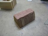
But it cleans up ok....


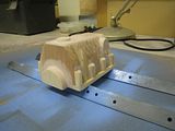
You could possibly use a green sand core with this casting, but I have been frustrated in the past with green cores breaking off when I separated the flask - so I decided to go with a bonded sand core. I have to make a core box:


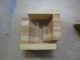
There's a protuberance inside the casting to provide a boss for the oil pickup pipe:


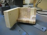
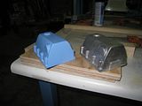
And here's the first article next to its pattern. The finish is pretty good, the pattern pulled nicely and I poured a usable casting first time out. Easy gating and no shrinkage issues at the flywheel end despite the bulk of metal there.


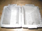
I had used 30# sand for the core of the first casting. That's perfectly usable, but I wanted a finer finish, so the for the next casting I used 100# sand for the core. On the left is the 100# casting, on the right the 30#. The surface finish is definitely better- but the core is harder to make. I use Sodium Silicate as a binding agent, and the finer sand makes it harder for CO2 to penetrate and harden the core. It took a few tries to get the core to harden up properly.


Stay tuned for more pics....
 
Nice job Jason. I've read about pattern making and casting, but never have tried to do it myself. It makes a lot of sense to put your time and efforts into the patterns, so that you can recreate items at will.

Someday I know I'll try it too. Need a shed just for the patterns. I doubt you can bring yourself to ever throw them away.

Rich
 
The conrods on the Wallaby are specified as being bronze. That's a new one for me. I've only ever cast Al before. I thought I'd get some practice by melting down some old brass plumbing fittings I've been stockpiling. I figure brass and bronze are roughly the same so far as their casting behavior is concerned.

A bit hotter than an Al melt:


The density of brass is a surprise when you are used to dealing with Al. It also seems much harder to skim off the dross. It's hard to see the surface of the metal with the glow, and I think the oxides reform very quickly. Oh yeah - and watch out for the fumes. Do it outside, stand upwind, wear a respirator. I maybe a bit paranoid, but I really don't want metal fume fever.

It's bit messier on the pour:


But the surface finish of the face is actually pretty good if you don't have any dross inclusions:


A cut through on the ingot shows clean metal:


5.9 kg of scrap brass to 5.3 kg of brass ingot.
Time to make me a pair of brass balls!

Does any body know a good source for buying an ingot of bearing bronze (E.g.932)?
 
The Wallaby is intended as a "real" engine, in so far as it was designed to go into model locomotives and boats where it could chug away for extended periods of time. As such it buttons up most of it's moving parts so they can be bathed in oil. A timing cover at one end of the engine covers the timing gears and provides a place to mount an oil pump, points and a distributor.

Here's the pattern and the casting:


I used a green sand core for this. With a generous draft I could pack in the sand for a reasonable finish while still getting a good pull on the pattern.


The nice thing about making your own castings is that you can always knock out a few spares:


I may try gating this through the wall thickness rather than into the side of the wall. I think that should provide enough feed and it will avoid having to clean up the gate stub on the side wall.
 
The most complex casting for the Wallaby is the engine block. It's forced me to push my envelope in terms of pattern and core box making.

The shape of the engine block is essentially an extruded profile that has various bits tacked to the outside. It's made as a split pattern. On the drag half of the pattern (left) you can see an oil filler protrusion and a boss for the water inlet. On the cope side of the pattern (right) you can see the bump that will accommodate the camshaft and a boss that will provide an oil feed to the crankshaft.


When you put them together you get an idea of the full shape.


The engine block is cored to provide cavities for the camshaft, water jacket and crank shaft. It's very useful to visualize this before you try to make a core box. Here's a CAD rendering I made:

 
What did you paint the pattern with? Is it grey primer?

Yes - Rustoleum Painters Touch primer. I will follow that up with a top coat of glossy color to protect the surface and give a better release from the sand.

I noticed the other day that some primers specifically claim to have a filler property that will smooth over minor surface imperfections. I'm going to try that- smoothness being a desired goal for pattern surfaces.
 
Do you have to provide holes for the cylinder openings on the top of the crankcase patterns as shown in your 3d mockup?
Rich
 
Do you have to provide holes for the cylinder openings on the top of the crankcase patterns as shown in your 3d mockup?
Rich

Nope. What I have to do it add core prints to the top and bottom of the pattern. The top and bottom of the core then can be supported in them. When the Al flows between the core and the sand cavity I'll end up with with a suitably sized hole for the cylinder bores. I'll post some more pictures of this and it will become clear.
 
Some more on the subject of brass/bronze casting:

When I poured my brass ingots into the standard muffin tin mold I noticed that the surface of the ingot was very rough and apparently oxidized. In comparison an Al ingot has a pretty clean top. I thought I might of being doing something wrong. I bought an ingot of 932 bronze from Atlas Metals of Colorado, and lo and behold, it has a similar pattern of rough oxidization on the top of the ingot. I suppose that's just a property of copper alloys.

From left to right:

Commercial bronze ingot
Mold side of homemade brass ingot
Air side of homemade brass ingot
Commercial Al ingot (that's dust on the top)


Conclusion - watch out for oxidization with copper alloys. I don't have much of a problem with dross inclusions on Al castings, but it could be that dross filters within the mold would really come into their own with copper alloys.
 
So it's time to try to cast some parts in brass. Specifically:

* the flywheel - specified as CI, but brass is heavier, I can melt it, and it's what I have.
* oil pump housing
* bolt on crankshaft counterweights.

Here we go:


Check out the backside. This is on the side of the mold (petrobonded sand) that was more lightly packed (to avoid moving the part line).
The brass has invaded the sand with these ridge patterns. It's totally nasty from a surface finish standpoint. It probably has sand inclusions as well.


Here's the yield. The question is- can we machine these to a good enough result?


Turning, turning, turning....


So the flywheel turned out ok, but that crud on the outside is very hard and would blunt the hss tool after 2 passes. I had to repeatedly regrind the tool until I got rid of the hard skin.


How do you get a good surface finish with brass castings? If a brass casting expert can chime in, that'd be great- otherwise I think I'll look at the Navy Foundry Manual and see what it says about casting defects for copper alloys.
 
Very odd surface finish on the OD of the castings. Does it get worse the farter it gets from the ingate?
 
Very odd surface finish on the OD of the castings. Does it get worse the farter it gets from the ingate?

No - I'd say it's at it's worst in the well I made at the bottom of the sprue. I've been perusing brass postings over at alloy avenue and I have a few variables to play with:

* Less pressure - It looks like brass doesn't do well with sprue extensions- and the additional pressure could be forcing the brass into the loose packed drag sand.

* Have the drag side be the tight packed side. If the cope is the loose packed side it won't have gravity trying to push the metal into the loose sand.

* Actually measure the melt temperature rather than just eyeball it. I may have been too hot - although I have a hard time believing that.

* Make a proper runner and gate system designed for brass.

* What kind of brass is this? It was derived from old plumbing fittings. I'm really not sure what it is.

I'm happy enough with the flywheel (after machining all surfaces) - but I'll re-pour the other pieces and try to get a better result.

Also - I think carbide tooling is probably a good idea to take off the skin of brass castings.
 
No - I'd say it's at it's worst in the well I made at the bottom of the sprue. I've been perusing brass postings over at alloy avenue and I have a few variables to play with:

And didnt bother to say hello?? Shame on you!

yes your gating and head pressure are probably your two biggest problems. Did you riddle in your first bit of sand? If you didnt that would explan the surface finish on the OD of the parts (I was thinking it was some sort of dross thats why I asked about its location from the sprue)
 
And didnt bother to say hello?? Shame on you!

Yes - I should do that - lot's of good info at alloyavenue.

Did you riddle in your first bit of sand?

Yes - I pretty much riddle all my sand. I've been cycling through the same batch of petrobond sand for a while now- and I don't have a muller. I've tried to throw out as much of the blackened sand as I can, but inevitably the sand quality has been declining, riddling all the sand helps to mix it together....but I really need to get/build a muller.
 
Well now im back to trying to figure out what is that on the OD of the casting...Grrrr thanks for that!!
if you have a good gear reduction drill one of those plaster mixers works out ok for mulling small batches of petrobond.
 
Ok - so I wasn't happy with surface finish of the brass, and machining it was a PITA. Time to take some (hopefully) corrective actions.

* Try a proper gating system. Some of the posts I saw at alloy avenue suggest a well at the bottom of the sprue along with a narrow/deep runner.
* No sprue extensions. You need enough pressure to get the metal into the cavity, bit too much pressure just forces the metal into the sand and causes surface finish issues.
* The second side of the mold you pack generally has looser sand because you don't want to mess up the part line. Make the tight packed sand the drag. Make the loose packed sand the cope. That way gravity works in our favor with respect to not forcing metal into loose packed sand.

In general I think the lower density of Al has been more forgiving and has allowed me to get away with not paying attention to these things. Brass/Bronze is heavier and brings these issues to the fore.

Here's the mold:


I poured this in C932 bronze. I couldn't really tell the difference between brass/bronze as far as melting/casting behaviour went. It was interesting to note that I run my furnace with a reducing setting. With the lid closed the surface of the crucible was shiny molten metal, but as soon as I opened it a scum of oxides formed on the melt surface.

Here's the result (cope side):


Note the cast counterbore for the flywheel. That was an upside down green sand core. I was happy it didn't fall off when the metal hit it.

And here's the drag side:


I'm happy with that surface finish. It's a qualified success. One of the parts (the oil pump housing) didn't fill. Maybe the gate was too small.

Here's the yield and their original patterns:


The bronze machined very nicely. I used carbide tooling this time- but even with HSS I think it would be easier to machine than the crappy finish on the brass.


In general I'm pleased with this. I think I have enough brass/bronze chops to make the rest of my parts. Dealing with brass/bronze has forced me to learn a few things I can feedback into Al castings to help me get more consistent/better surface finishes.
 
Last edited:
I've been slouching towards getting the engine block cast. It needs a core and therefore a core box.
The core makes a hole in the casting for:

1) Through holes for the cylinders.
2) A water jacket around the cylinder liners.
3) Crank cavities at the base of each cylinder.
4) A camshaft gallery that runs parallel to the crank.

This is the artists impression:


It's a bit tricky to make (at least for me) because you have to think in terms of negative space. The previous work by bezalel2000 was a very valuable reference. I contemplated several ways to make this core but ended up copying most of bezalel2000 core box design.

Here it is laid out:


And here is another shot as it goes together:


Ready for sand packing:


Packed with sand:


I'm using NaSiO2 for the binder, so I'm gassing it with CO2 to kick it off.


Getting the core out of the box is a bit of a PITA. It can be done, but in retrospect I should have been more generous with the draft. This was a trial run, and I ended up breaking the core- but I'm hoping the box will "loosen" up a bit for subsequent cores.


Incidentally a broken core can be repaired with wood glue. I don't want to have to do that, but its nice to know it works.


And here I'm checking it in the position it will assume in the mold. Even with the repair it has no problems holding up to the force of gravity.


So now I just have to get the core prints attached to the block pattern, and I'll be ready to try pouring a block.
 
Ok- let me see if I can pour an engine block....

I have a core. It's still a ***** to get out of the core box. It broke in a couple of places, but I fixed it with wood glue.


I have a pattern with core prints attached.


The patterns were a good pull from the sand. Careful attention to pattern drafting pays off. All that work and all I wanted to do was make a hole in the sand. I forgot to get a picture of the core in situ- but trust me, I put it in there.


Gratuitous furnace shot. I normally cast in the morning. This work was done as the sun was cheesing it over the hills. You see a lot more flame detail at dusk- that's probably a good diagnostic if you know what you are looking at.


The big reveal.


Nice water jacket and cylinder holes.


Good of this side (the drag side).


Issues on this side (cope side). If you look at the timing plate mount you can see that the metal did not quite get to the uppermost extremity of the mold.


Ok - so I can't use this casting, but I'm still pleased that I took this through the process and didn't find anything I can't fix. It's one thing to worry about everything, and another thing to go through a process and find out what the real problems are.

Here's the TODO list.

1) Shorten the runners. This was perilously close to a short pour.
2) There's only about an inch of head between the top of the sprue and the problem area. Add a sprue extension. Get some pressure into the mold.
3) There was some glug,glug,glug as the mold filled. Even though I haven't had a problem with venting in petrobond, I think this mold needs it at the high points.

This casting will be recycled - but as I cut it up I'll be able to check for any issues with respect to core placement and/or wall thickness.
 

Latest posts

Back
Top